US991672A - Printing-telegraph. - Google Patents
Printing-telegraph. Download PDFInfo
- Publication number
- US991672A US991672A US53613810A US1910536138A US991672A US 991672 A US991672 A US 991672A US 53613810 A US53613810 A US 53613810A US 1910536138 A US1910536138 A US 1910536138A US 991672 A US991672 A US 991672A
- Authority
- US
- United States
- Prior art keywords
- type
- controlling
- impression
- movements
- magnetizable member
- Prior art date
- Legal status (The legal status is an assumption and is not a legal conclusion. Google has not performed a legal analysis and makes no representation as to the accuracy of the status listed.)
- Expired - Lifetime
Links
- 230000007246 mechanism Effects 0.000 description 149
- 230000001276 controlling effect Effects 0.000 description 140
- 230000005291 magnetic effect Effects 0.000 description 135
- 230000033001 locomotion Effects 0.000 description 107
- 230000000994 depressogenic effect Effects 0.000 description 11
- XEEYBQQBJWHFJM-UHFFFAOYSA-N Iron Chemical compound [Fe] XEEYBQQBJWHFJM-UHFFFAOYSA-N 0.000 description 7
- 238000013016 damping Methods 0.000 description 7
- 238000010276 construction Methods 0.000 description 5
- 239000012530 fluid Substances 0.000 description 4
- 229940000425 combination drug Drugs 0.000 description 3
- 230000003247 decreasing effect Effects 0.000 description 3
- 239000011810 insulating material Substances 0.000 description 3
- 229910052742 iron Inorganic materials 0.000 description 3
- 239000002184 metal Substances 0.000 description 3
- 229910052751 metal Inorganic materials 0.000 description 3
- 230000004048 modification Effects 0.000 description 3
- 238000012986 modification Methods 0.000 description 3
- 239000011435 rock Substances 0.000 description 3
- 210000005069 ears Anatomy 0.000 description 2
- 230000008520 organization Effects 0.000 description 2
- 238000004804 winding Methods 0.000 description 2
- RYGMFSIKBFXOCR-UHFFFAOYSA-N Copper Chemical compound [Cu] RYGMFSIKBFXOCR-UHFFFAOYSA-N 0.000 description 1
- 230000008901 benefit Effects 0.000 description 1
- 230000005540 biological transmission Effects 0.000 description 1
- 229910052802 copper Inorganic materials 0.000 description 1
- 239000010949 copper Substances 0.000 description 1
- 230000000881 depressing effect Effects 0.000 description 1
- 230000000694 effects Effects 0.000 description 1
- 238000009413 insulation Methods 0.000 description 1
- 230000001788 irregular Effects 0.000 description 1
- 230000005415 magnetization Effects 0.000 description 1
- 229920000136 polysorbate Polymers 0.000 description 1
- 230000000717 retained effect Effects 0.000 description 1
Images




Classifications
-
- H—ELECTRICITY
- H04—ELECTRIC COMMUNICATION TECHNIQUE
- H04L—TRANSMISSION OF DIGITAL INFORMATION, e.g. TELEGRAPHIC COMMUNICATION
- H04L13/00—Details of the apparatus or circuits covered by groups H04L15/00 or H04L17/00
- H04L13/02—Details not particular to receiver or transmitter
- H04L13/08—Intermediate storage means
Definitions
- n4 NORRIS PETERS co., WASHINGYON, n c.
- This invention relates to printing telegraphs designed for use particularly in those situations where the great desideratum is not speed, but certainty and accuracy of operation, as, for example, in army and navy apparatus, where in the sending of ranges from the range finders to distant gunners, it, is, of course, of vital importance that there should be no errors in transmisison.
- Step by step devices have been devised and to some extent used in these situations, but they have not given satisfaction because they are uncertain in operation, as by losing steps, even when presumably in operative condition, and because they are very liable to get outof adjustment and, therefore, become useless.
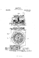
- Figure 1 is a diagrammatic view of an or ganization comprising a transmitter and a distant receiver or receivers, with main line circuits between the former and the latter controlling devices for moving the type wheels of the receiver to printing position, and additional circuit controlling devices for locking the wheels in that position, for printing or taking an impression therefrom, and for shifting the paper at the receiver;
- Fig, 2 is a plan view, and Fig. 3 a side view, of the transmitting instrument;
- Fig. 4 is a front view, and Fig. 5 a side View, partly broken away, of one of the receivers;
- Fig. 6 is a vertical section on line 6 of Fig. 7
- Fig. 7 is a horizontal section on an enlarged scale of the transmitter;
- Fig. 8 is a sectional detail of the lower part of the transmitter illustrating particularly manually operated main switch or circuit closing means controlling the circuits at and from the transmitter and which in one position closes simply the paper shifting circuit;
- Fig. 9 is a vertical section on the irregular line 9 of Fig. 6, also illustrating the main switch mechanism of the latter figure;
- Fig. 10 is a side elevation, Fig. 11 a plan view, and Fig. 12 a front elevation of one of the receivers, the casing thereof being shown in section;
- Figs. 13, 1a and 15 are details illustrating particularly the paper shifting and typewheel locking mechanism at the receiver;
- Fig. 16 is a bottom View of the transmitter illustrating the main switch mechanism of Figs.
- Fig. 17 is a detail, partly in section, of a portion of the type wheel setting mechanism in the receiver;
- Fig. 18 is a section on the line 18 of Fig. 17.
- Fig. 19 is a diagrammatic view illustrating a modification hereinafter described.
- Fig. 1 it may be well to note that although two receivers are shown (at the receiving station) for operation by the transmitter, the number may be increased or decreased, and also that these receivers may be located at any distance from each other, or at any distance from the transmitter, so long as they are within the field of operation of the latter and of the circuits operated thereby.
- An additional receiver is also shown (at the transmitter) for a purpose hereinafter referred to.
- the transmitter.Tlie mechanism of the transmitter is inclosed in a casing 1, and, with the latter, is mounted on a base 2 of suitable insulating material; the casing 1 being mounted on said base in such way that it may be readily removable therefrom, while the transmitter parts are, with a few exceptions hereinafter noted, mounted on posts 3 projecting upwardly from the base.
- a block 5 of insulating material Secured to posts 3 by screws 1, at a suitable distance above base 2 to provide for movements of certain circuit closing means hereinafter referred to, is a block 5 of insulating material, and at a suitable distance above said block there is also secured to said posts by insulated screws or pins 6, a ring 7, of 1 of block is a main switch 29 of spring insulating material preferably wound with insulated wire 7 the turns of which are symmetrically distributed along the ring.
- a substantially triangular shaped bracket 8 At the upper end of posts 3 there is secured a substantially triangular shaped bracket 8.
- This bracket 8 is provided centrally with a long vertical bearing 9 for a rotary sleeve 10 provided at its lower end with an arm 11, projecting radially therefrom in diametri cally opposite directions.
- the sleeve 10 is secured by a set-screw 12 to the downwardly projecting hub of a radial arm 13 encircling said sleeve at its inner end.
- the arm 13 has fulcrumed to it, by a pin l t, the rear end of arm 15, which is provided at its front end with a handle 16 by which it may be turned in either direction.
- Pin 14 is held securely in arm 13, and therefore in proper engagement with corresponding openings in the downwardly bent flanges 17 of the arm 15, as by a set screw.
- Arm 11 carries at its ends a pair of downwardly bent spring contact brushes 19, 20, suitably secured at their upper ends to ears 21, projecting from the arm 11, but insulated from said ears and, therefore, from the arm 11, as shown or in any other suitable manner. Arm 11 is also provided at its opposite ends with a pair of spring arms 22, 23 carrying respectively at their outer ends metal contact rollers 21, 25, bearing against the inner wired surface of the ring 7 at diametrically opposite points.
- the currents traversing these circuits are delivered into the wiring 7' on ring 7 and fed thence to the receiver orrcceivers by a number of main line wires or circuits (at least three) 38, 39, 4:0 connected with the wiring 7, equidistantly from each other or 120 apart circumferentially of the ring 7 with equal amounts of electrical rcsistanee between each adjacent two.
- the characters which the transmitter as here shown is designed to transmit and have printed at the receiver consists of numerals from 0" to 9 and the parts of the transmitter and receiver are so arranged and adjusted. relatively to each other that as the arm 15 is thus rotated and then brought to rest opposite the numeral selected for transmission the receiver type wheel ('50 will correspondingly rotate and then come to rest with a like numbered type at the printing point.
- casing 1 has fixed to it a flanged plate -11 which may have a dial bearing the numerals 0 to 9 and the flange of which will preferably be provided with notches 42 in line with these numerals and which, coacting with a projection 43 on handle 15 as the latter is depressed, serves to center said arm accurately with relation to plate n for the numeral to be transmitted.
- the work performed by the currents traversing main line wires 38, 39, 40 is simply that of selectively positioning the type or type wheel according to the type to be print-ed from.
- the transmitter is provided with others leading to the receiver or receivers for producing the impressions from the type or type wheel, shifting the recording blank or blanks printed upon for proper spacing be tween numerals and groups of numerals received, and locking and also centering the type or type wheel in the printing position to which it may be rotated.
- the printing or impression circuit is controlled by main switch 29 and by an auxiliary switch 1% controlled by arm 15, and adapted to engage a contact 4:5; this circuit (when both these switches are depressed) consisting of wire 33, switch 29, contact 61, wire 34:, wire 46, switch at, contact 45, wire 17, wire 48 and wire 49 to ground at 50. Included in this circuit is an impression magnet 51 which, with the parts operated by it, will be hereafter more fully described in connection with the receiver mechanism.
- the paper shifting circuit is in two parts.-one of which is controlled by switches 29, 4 1, and consists in the depressed position of the switches, of wire 63, switch 29, contact 31, wire 3st, wire 4L6, switch 4%, a contact 58 engaged thereby, wire 54, to a paper shifting magnet 55 at the receiver, and wires 56, as, to ground at 50,and the other of which is controlled simply by switch 29, and in the elevated position of the latter, where it engages a contact 57, the circuit consisting of wire 33, switch 29, contact 57, wire 58, wire 54, to magnet 55, and wires 56, 4:9, to ground.
- the first circuit is,
- the one that is used when during the transmitting operation a character transmitted is printed at the receiver, the paper then being shifted simply to properly space the characters transmitted, received and printed; while the second circuit is used at other times, namely, after a group of characters (or words, if letters should be used) or a message has been transmitted and then for the purpose of spacing between groups of characters (words) or messages or for shifting paper in testing etc and while this circuit is being used no transmitting or printing is being done.
- the circuit for locking the type wheel at the receiver during printing is that just described for shifting the paper, the mechanism for so locking it consisting of a lever controlled by paper shifting magnet 55 (Figs. 13 to 15), as hereinafter described.
- the rccez'oer.r1s the two receivers shown are identical in construction, a description of one will be suflicient. Selecting therefore the receiver mechanism shown at the left of Fig. 1, it comprises, among other things hereinafter fully described, a type wheel 60 and impression platen or roller 61, adapted to be swung into contact with said type wheel, a pair of drawing rollers 62, 63, for shifting the recording blank or blanks on which the printing or impressing is done and which is preferably but not necessarily in the form of a long strip or web 64 of paper, and the lever 59 (Figs. 13 to 15) for engaging and thereby centering the type 'wheel and locking it against rotation during the printing operation.
- a type wheel 60 and impression platen or roller 61 adapted to be swung into contact with said type wheel
- a pair of drawing rollers 62, 63 for shifting the recording blank or blanks on which the printing or impressing is done and which is preferably but not necessarily in the form of a long strip
- the type wheel 60 is, as best shown in Fig. 17, secured to a sleeve 67 mounted loosely on a spindle 68 on which it is held in proper vertical position by the engagement of the lower end of said sleeve with a shoulder 69 on said spindle and the engagement of the upper end of said sleeve with a collar 70 secured to the spindle 68 by a set screw.
- Spindle 68 is mounted, so as to turn therein, in two iron plates 71, 72, which, with a copper shell 73, form a chamber in which oscillates a polarized armature 76, the hub 77 of which is pinned to spindle 68 so as to rotate the latter, as will presently appear.
- This chamber has preferably tight joints so that it may act as a receptacle for oil or other suitable fluid for damping the movements of the armature 76 and parts carried thereby.
- This is of advantage in that it makes it possible to use weak currents to operate armature 76 and parts connected therewith.
- the plates 71, 72 and shell 7 3 are suitably supported on a bracket 7 8 mounted on the base 66.
- the contracted upper end of spindle G8 is journaled in. a bearing 79 mounted in a horizontal arm 80 at the upper end of the bracket 78; this arm 80 having attired to it a dial 82 numbered from 0 to 9, with which coacts a pointer 83 fixed to the upper end of the rotary spindle (i8.
- Plates 71, 72 are connected with a permanent magnet 84 and shell 78 is inclosed by an annealed iron ring 85 wound with insulated wire, the turns of which are symmetrically distributed around the ring.
- the shell 73 interposed between ring 85 and armature 76 also serves to damp the movements of the latter and parts connected therewith.
- the line wires 38, 39, 4O connect with the wire on this ring 85 at equidistant points, or, in other words, 120 apart circumferentially of said ring, as in the case of transmitter ring 7.
- the magnetizable element or armature "("6 will take up a position that will bring its poles in alinement with the magnetic poles of the ring 85, and, as the arm 15 of the transmitter is rotated, the currents delivered from the transmitter will cause the magnetic poles in ring 85, or in other words, the points of greatest influence of said magnetic field, to shift around said ring, carrying the magnetizable element or armature 76 and spindle (38 in unison with the movements of said arm 15.
- Type wheel 60 will be caused to rotate with spindle 68 by a spring connection 86 between said spindle and a pin 87 projecting downwardly from said type wheel, and the type wheel thus moving in unison with the arm 15 will bring to the printing point, opposite the printing roller 61., the numeral to which the handle 15 has been moved in the transmitter.
- T he flexible connection just referred to between the type wheel 60 and spindle 68 is preferred, as with it any slight inaccuracy in the movement of the type wheel in presenting the selected character to the printing point may be rectified by the centering and locking devices which will presently be described.
- lrintingor i npression platen 61 is in the form of a roller and mounted on an arm. 88 secured at its lower end to the armature 89 of the magnet 51 supported in bracke' 78, in which said armature is'also pivotally mounted.
- This magnet 51 is, as before described, connected with a negative pole of battery 32 by a circuit controlled by switches 29, ll at the transmitter, the former (29) being manually controlled and held depressed in engagement with contact 31 dur ing the operation of transmitting, while the latter (44-) is controlled by the handle 15 and rod 52 and is only depressed into engagement with contact 45 when arm 15, and therefore rod is depressed by the operator, to have a transmitter numeral printed in the receiver.
- printing platen 61 is in the form of a roller, as shown, and is of such a character that it may be loaded with ink so that the impression made on strip 6% by the type of wheel (30 will be colored instead oi? merely embossed on said strip.
- switch 44 which latter is thus disengaged from contact 45 so as to break the circuit through magnet 51, which will then release its armature 89 so that printing platen 61 will fall away from type wheel 59 to normal position, in which position it is arrested by a stop 90 (see Fig. 10).
- the strip 64 which furnishes the blank or blanks to be printed is supplied from a web wound on a reel 91 removably mounted at on a support 93, which is held in proper supporting position above magnet 8% y plate 9st secured on. opposite sides of said magnet.
- Both of the rolls are preferably also toothed, and the teeth on roll 62 are utilized for rotating the rolls.
- the means for engaging these teeth on roll 02 for such rotation consists of a pawl 101 engaging said teeth and carried by the rocking armature 102 of the magnet 55, said armature being fixed to shaft 97.
- Pawl 101 is pivotally mounted on said armature and its toothed end is held yieldingly in engagement with said teeth by a spring 103 carried by the armature and engaging the tail end of said pawl, the construction being such that the pawl will rotate roll 02 when moved in one direction and ride idly over the teeth thereof when it is moved in the opposite direction, the roll 62 being prevented from rotating when the armature 101 and pawl 102 are moved by the energizing of the magnet 55 by a spring pressed locking pawl 110.
- Magnet 55 is, as before described, in a circuit leading from the negative pole of battery 32 and controlled by the main switch 29 and switch 44, said circuit being closed when both switches are in their depressed positions, in other words when the arm 15 has been depressed by the operator to have the character transmitted printed at the receiver.
- At the closing of this circuit magnet is energized and rocks its armature 102 from the position shown in Fig. 13 to that shown in Fig. 14, against the tension of a spring 104 coiled about shaft 97 with one end secured to bearing 98 and the other to a collar 105 fast to said shaft.
- armature 102 pawl 101 rides idly in the teeth on roll 62, so that there is no movement of the strip 64 which is therefore stationary during the printing operation.
- arm 15 is relieved of pressure by the transmitter operator and the circuit through magnet 55 therefore opened, magnet 55 is deenergized and armature 102 moved to normal position (Fig. 13) by spring 104.
- armature pawl 101 On this movement of the armature pawl 101 will interlock with the toothed periphery of roll 62 and rotate it and thus, with roll 63, feed strip 64 one step, presenting a fresh portion thereof at the printing point for the next impression.
- Shifting of the strip 04 may also be effected, as before stated, independently of arm 15. This is done by raising switch 29 into engagement with contact 56, thus closing the circuit from battery 32 through magnet 54, consisting of wire 33, switch 29, contact 57, wire 58, wire 54, magnet and wires 56, 49. to ground.
- the locking of type wheel 60 prior to and during the printing operation is effected on the closing of the circuit through magnet 55, as just described, by a bell crank lever 59 pivotally mounted on a bracket secured to plate 71.
- One arm of this lever is adapted to enter between pins 106 projecting downwardly from type wheel 60 and thus lock it a ainst rotation and also center it properly with relation to the printing point should there be any slight inaccuracy in so presenting it on the part of the armature 76.
- Such centering is facilitated by the spring connection 86 between spindle 68 and type wheel 00.
- the other arm of the lever 59 is engaged on one side by a lateral projection 107 on the tail end of pawl 101, and on the other side by a lateral projection 108 on a plate 109 secured to armature 102. It follows that as armature 102 is rocked from normal position (Fig. 13) to the position shown in Fig. 14, plate 109 moving with it will rock lever 59 to the position shown in Fig. 14 and cause its other arm to enter between and interlock with two of the pins 106 on type wheel 60, and thus accurately center the type wheel with relation to the printing point and securely hold it there during the printing operation. hen magnet 55 is deenergized and armature 102 rocked from the position shown in Fig. 14 back to that shown in Fig. 13, the projection 107 on the tail of pawl 101. will rock the lever 59 in the opposite direction, thereby disengaging saidlever from the type wheel 60 and returning it to the position shown in Fig. 13.
- switch 29 occupies its normal position (shown in Fig. 1) out of engagement with the lower and upper contacts 31, 57. In this position of the switch 29, all the circuits 110 from the transmitter to the receiver, as well as from the battery 32 to contact rollers 24,
- the handle 15 is at 0 or at the point where left by the operator during the last transmitting operation, and the type wheel 60 of the receiver is in the same position, that is to say, with the 0 at the printing point or with that type numeral at the printing point at which the arm 15 has been left in the transmitter.
- the operator being now desirous of sending a message, will first depress switch 29 into engagement with contact 31, thereby closing the circuit from battery 32 to contact rollers 24, 25, and thence through the wiring 7 of ring 7 and main line wires 38, 39, 40, to the ring 85 in the receiver, all the other circuits from the transmitter to the receiver being still open. He will then turn arm 15 to and arrest it at the numeral on indicator plate 41 which he desires to transmit and have characters transmitted.
- switch 44 closes the circuit from the negative pole of battery 32, by wires 54, 56, 49 and ground, through magnet 55, which is thus energized, its armature 102 being moved thereby from position in which it is shown in Fig. 13 to the position shown in Fig. 14 and through the connections hereto fore described, including projection 10S, moving the locking lever 59 into engagement with the pins 106 on the type wheel 60, which is thus centered and locked against rotation during the printing operation.
- switch 44 By engagement with the contact 45, switch 44 at the same time closes the circuit from the negative pole of battery 32, by way of wires 47, 48, 49, and ground, through the magnet 51 which, attracting its armature S9 and impelling printing roller or platen 61 against the printing strip 64 and type wheel 60 so as to impress on said printin strip the numeral presented at the printing point by said type wheel.
- the operator at the transmitter will then release the arm 15 from downward pressure, thereby permitting contact 41 to disengage itself from the two contacts 45, 53. Its disengagement from contact 44 breaks the circuit through type wheel 60.
- the purpose of providing it at the transmitting station is an important one, namely, that it enables the transmitter operator to ascertain at a glance with absolute certainty whether or not the receiving instrmnents at the receiving station, with which this receiver at the transmitting station is in parallel, are operating accurately.
- main line wires may be reduced to two as in the modification illustrated in Fig. 19.
- the positive pole of a battery 132 is connected by wire 136 with an oscillating arm 115 contacting on its upper surface with the under surface of a wire wound segment 107, the wire winding 107 on which is insulated except those portions thereof with which arm 115 makes contact as it is moved back and forth.
- the terminals of wire 107 are connected by main line wires 138, 139 with a pair of electromagnets 185, 185 respectively, on the heel iron 1'76 of which is pivotally mounted an oscillating armature 176.
- Magnets 185, 185 are connected with ground by wires 186, 187, 188, coil 176, wire 189, magnet 151 and wire 190.
- This heel iron is so shaped as to project upwardly between the magnets and to provide an annular support for pivoted coil or armature 176 in line with the uawardly projecting cores of the magnets which are shown as contacted at their upper ends and inclined away from each other so as to provide a between each of them and armature 176 increasing in width in an upward direction.
- the result of this construction is that as the current is decreased in one 111 gnet and increased in the other magnet one magnet wi l repel the coil 176 more strongly than the other so that the coil will move upwardly in one gap and downwardly in the other.
- Printing or impression magnet 151 is controlled by main line circuit 138, 139 and the circuit consisting of wires 186, 187, 188, coil 176, and wires 189, 190 to ground from magnets 185, 185 these circuit connections being of course con trolled by arm 115 so that while said arm is in contact with wiring 107 magnet 151 is energized, thereby attracting its armature and retaining platen 161 in its elevated position.
- What I claim is 1.
- a printing telegraph the combination of type and impression mechanisms, one movable relatively to the other for selectively positioning said mechanisms in proper correlation for impressions from the different type, of a movable magnetizable member connected with and controlling such movements of said movable member, magnetic devices and circuits therefor providing a magnetic field for controlling tl e movements of said magnetizable member, and means controlling said circuits for shifting the points of greatest influence of said magnetic field upon said magnetizable member and thus moving it and said movable memleer in accordance with the type selected for impression.
- a printing telegraph the combination of type and impression mechanisms, the former being movable relatively to the latter for selectively positioning it in proper correlation thereto for impressions from the different type, of a rotary magnetizable member connected with and controlling such movements of the type mechanism, magnetic devices and circuits therefor providing a magnetic field for controlling tl e movements of said magnetizable member, and means controlling said circuits for shifting :the points of greatest influence of said magnetic field upon said magnetizz-ible member and thus moving it and said type mechanism in accordance with the type selected for impression.
- a printing telegraph the combination of type and impression mechanisms, one movable relatively to the other for selectively positioning said mechanisms in proper correlation for impressions from the different type, of a movable magnetizable member connected with and controlling such movements of said movable member, magnetic devices and circuits therefor pro iding a magnetic field for controlling the movements of said magnetizable member, means controlling said circuits for shifting the points of greatest influence of said magnetic field upon said magnetizable member and thus moving it and said movable member in accordance with the type selected for impression, an impression magnet controlling the relative to and fro movements of the type and impression mechanisms in making impressions, and a circuit provided with suitable circuit closing means controlling said impression magnet.
- a printing telegraph the combination of type and impression mechanisms, one movable relatively to the other for selectively positioning said mechanisms in proper correlation for impressions from the different type, of a movable magnetizable member connected with and controlling such movements of said movable member, magnetic devices and circuits therefor providing amagnetic field for controlling the movements of said magnet-izable member, means controlling said circuits for shifting the points of greatest influence of said magnetic field upon said magnetizable member and thus moving it and said movable member in accordance with the typeselected for impression, means for feeding a recording blank or blanks between the type and im pression mechanisms to receive impressions therefrom, magnetic devices controlling said feeding means, and a circuit with suitable circuit closing means controlling said magnetic devices.
- a printing telegraph the combina tion of type and impression mechanisms, the former being movable relatively to the lattor for selectively positioning it in proper correlation thereto for impressions from the different type, of a movable magnetizable member connected with and controlling such movements of the type mechanism, magnetic devices and circuits therefor providing a magnetic field for controlling the movements of said magnetizable member, means controlling said circuits for shifting the points of greatest influence of said magnetic field upon said magnetizable member and thus moving it and said type mechanism in accordance with the type selected for impression, means for feeding a recording blank or blanks between the type and impression mechanisms to receive impressions therefrom, magnetic devices controlling said feeding means, and a circuit with suitable circuit closing means controlling said magnetic devices.
- a printing telegraph the combination of type and impression mechanisms, one movable relatively to the other for selectively positioning said mechanisms in proper correlation for impressions from the different type, of a movable magnetizable member connected with and controlling such movements of said movable member, magnetic devices and circuits therefor providing a magnetic field for controlling the movements of said magnetizable member, means controlling said circuits for shifting the points of greatest influence of said magnetic field upon said magnetizable member and thus moving it and said movable member in accordance with the type selected for impression, and means for locking the type mechanism against positioning movement during impress1ons.
- a printing telegraph the combination of a rotary type mechanism and impression mechanism coacting therewith, of a movable magnetizable member connected with and controlling the rotary movements of the type mechanism so as to selectively position it in proper correlation to the impression mechanism for impressions from the different type, magnetic devices and circuits therefor providing a magnetic field for controlling the movements of said magnetizable member, means controlling said circuits for shifting the points of greatest influence of said magnetic field upon said magnetizable member and thus moving it and said type mechanism in accordance with the type selected for impression, and means for looking the type mechanism against positioning movement during impressions.
- a printing telegraph the combination of a rotary type mechanism and impression mechanism coacting therewith, of a movable magnetizable member connected with and controlling the rotary movements of the type mechanism so as to selectively position it in proper correlation to the impression mechanism for impressions from the different type, magnetic devices and circuits therefor providing a magnetic field for controlling the movements of said magnet-izable member, means controlling said circuits for shifting the points of greatest influence of said magnetic field upon said magnetizable member and thus moving it and said type mechanism in accordance with the type selected for impression, magnetic devices and means controlled thereby for locking the type mechanism against rotation during impressions, and a circuit with suitable circuit closing means controlling said magnetic devices.
- a printing telegraph the combination of type and impression mechanisms, one movable relatively to the other for selectively positioning said mechanisms in proper correlation for impressions from the difierent type, of a movable magnetizable member connected with and controlling such movements of said movable member, magnetic devices and circuits therefor providing a magnetic field for controlling the movements of said magnetizable member, means controlling said circuits for shifting the points of greatest influence of said magnetic field upon said magnetizable member and thus moving it and said movable member in accordance with the type selected for impression, and means for centering the type mechanism and looking it against positioning movement during impressions.
- a printing telegraph the combination of a rotary type mechanism and impression mechanism coacting therewith, of a movable magnetizable member connected with and controlling the rotary movements of the type mechanism so as to selectively position it in proper correlation to the impression mechanism for impressions from the different type, magnetic devices and circuits therefor providing a magnetic field for controlling the movements of said magnetizable member, means controlling said circuits for shifting the points of greatest influence .of said magnetic field upon said magnetizable member and thus moving it and said type mechanism in accordance with the type selected for impression, and means for centering the type mechanism and locking it against positioning movement during impress1ons.
- a printing telegraph the combination of type and impression mechanisms, one movable relatively to the other for selec tively positioning said mechanisms in proper correlation for impressions from the different type, of a movable magnetizable member connected with and controlling such move ments of said movable member, magnetic devices and circuits therefor providing' a magnetic field for controlling the movements of said magnetizable member, means controlling said circuits for shifting the points of greatest influence of said magnetic field upon said magnetizable member and thus moving it and said movable member in accordance with the type selected for impression, magnetic devices and means controlled thereby for centering the type mechanism and locking it against positioning movement during impressions, and a circuit with suitable circuit closing means controlling said magnetic devices.
- a printing telegraph the combination of a rotary type mechanism and im pression mechanism coacting therewith, of a movable magnetizable member connected with and controlling the rotary movements of the type mechanism so as to selectively position it in proper correlation to the impression mechanism for impressions from the different type, magnetic devices and circuits therefor providing a magnetic field for controlling the movements of said magnetizable member, means controlling said circuits for shifting the points of greatest influence of said magnetic field upon said magnetizable member and thus moving it and said type mechanism in accordance with the type selected for impression, magnetic devices and means controlled thereby for centering the type mechanism and locking it against rotation during impressions, and a circuit with suitable circuit closing means controlling said magnetic devices.
- a printing telegraph the combination of type and impression mechanisms, one movable relatively to the other for selectively positioning said mechanisms in proper correlation for impressions from the different type, of a movable magnetizable member connected with and controlling such movements of said movable member, magnetic devices and circuits therefor providing a magnetic field for controlling the movements of said magnetizable member, means controlling said circuits for shifting the points of greatest influence of said magnetic field upon said magnetizable member and thus moving it and said movable memher in accordance with the type selected for impression, an impression magnet controlling the to and fro movements of the type and impression mechanisms in making impressions, a circuit provided with suitable circuit closing means controlling said impression magnet, means for feeding a recording blank or blanks between the type and impression mechanisms to receive impressions therefrom, magnetic devices controlling said feeding means, and a circuit with suitable circuit closing means controlling said magnetic devices.
- a printing telegraph the combination of type and impression mechanisms, one movable relatively to the other for selectively positioning said mechanisms in proper correlation for impression from the different type, of a movable magnetizable member connected with and controlling such movements of said movable member, magnetic devices and circuits therefor providing a magnetic field for controlling the movements of said magnetizable member, means controlling said circuits for shifting the points of greatest influence of said magnetic lield upon said magnetizable member and thus moving it and said movable member in accordance with the type selected for impression, an impression magnet controlling the to and fro movements of the type and impression mechanisms in making impressions, a circuit provided with suitable circuit closing means controlling said"i1npression magnet, magnetic devices and means controlled thereby for feeding a recording blank or blanks between the type and impression mechanisms to receive impressions therefrom and for locking the type mecha nism against positioning movement during impressions, and circuit connections with suitable circuit closing means controlling said magnetic devices.
- a printing telegraph the combination of type and impression mechanisms, one movable relatively to the other for selectively positioning said mechanisms in proper correlation for impressions from the different type, of a movable magnetizable member connected with and controlling such movements of said movable member, magnetic devices and circuits therefor providing a magnetic field for controlling the movements of said magnetizable member, means controlling said circuits for shifting the points of greatest influence of said magnetic field upon said magnetizable member and thus moving it and said movable member in accordance with the type selected for impression, an impression magnet controlling the to and fro movements of the type and impression mechanisms in making impressions, a circuit provided with suitable circuit closing means controlling said impression magnet, magnetic devices and means controlled thereby for feeding a recording blank or blanks between the type and impression mechanisms to receive impressions therefrom and. for centering the type mechanism. and looking it against positioning movement during impressions, and circuit connections with suitable circuit closing means controlling said magnetic devices.
- I11 a printing telegraph the combination of type and impression mechanisms, the former being movable relatively to the latter for selectively positioning it in proper correlation thereto for impressions from the different type, of a rotary magnetizable member connected with and controlling such movements of the type mechanism, magnetic devices and circuits therefor providing a magnetic field for controlling the movements of said magnetizable member, a receptacle containing said magnetizable member and a suitable fluid for damping its movements, and means cont-rolling said circuits for shifting the points of greatest influence of said magnetic field upon said magnetizable member and thus moving it and said type mechanism in accordance with the type selected for impression.
- a printing telegraph the combination of a rotary type mechanism and impression mechanism coacting therewith, of a movable magnetizable member connected with and controlling the rotary movements of the type mechanism so as to selectively position it in proper correlation to the impression mechanism for impressions from the different type, magnetic devices and circuits therefor providing a magnetic field for controlling the movements of said magnetizable member, and means, comprising rotary contacts and suitable contacting parts therefor, controlling said circuits for shifting the points of greatest influence of said magnetic field upon said magnetizable member and thus moving it and said type mechanism in accordance with the type selected for impression.
- a printing telegraph system the combination of a transmitting station and a receiving station provided with type and impression mechanisms, one of the latter being movable relatively to the other for selectively positioning said mechanisms in proper correlation for impressions from the different type, a movable magnetizable member connected with and controlling such movements of the movable member, magnetic devices and circuits therefor leading from the transmitting station providing a magnetic field for controlling the movements of said magnetizable member, means at the transmitting station controlling said circuits for shifting the points of greatest influence of said magnetic field upon said magnetizable member and thus moving it and said movable member in accordance with the type selected for impression, and a receiving instrument at the transmitting station having like type and impression mechanisms with the magnetic controlling devices thereof in parallel with those at the receiving station.
- a printing telegraph system the combination of a transmitting station and a receiving station provided with type and impression mechanisms, one of the latter being movable relatively to the other for selectively positioning said mechanisms in proper correlation for impressions from the different type, a movable magnetizable member connected with and controlling such movements of the movable member, magnetic devices and circuits therefor leading from the transmitting station providing a magnetic field for controlling the movements of said magnetizable member, means at the transmitting station controlling said circuits for shifting the points of greatest influence of said magnetic field upon said magnetizable member and thus moving it and said movable member in accordance with the type selected for impression, mechanism for feeding a recording blank or blanks between the type and impression mechanisms to receive impressions therefrom, magnetic devices for controlling said feeding mechanisms, and a receiving instrument at the transmitting station having like type, impression and feeding mechanisms with the magnetic controlling devices thereof in parallel with those at the receiving station.
- a transmitting station and a receiving station provided with type and impression mechanisms, one of the latter being movable relatively to the other for selectively positioning said mechanisms in proper correlation for impressions from the different type
- a movable magnetizable member connected with and controlling such movements of the movable member, magnetic devices and circuits therefor leading from the transmitting station providing a magnetic field for controlling the movements of said magnetizable member
- means at the transmitting station controlling said circuits for shifting the points of greatest influence of said magnetic field upon said magnetizable member and thus moving it and said movable member in accordance with the type selected for impression
- mechanism for feeding a recording blank or blanks between the type and impression mechanisms mechanism for locking the type mechanism during impressions
- magnetic devices controlling said feeding and locking mechanisms and a receiving instrument at the transmitting station having like type
Landscapes
- Engineering & Computer Science (AREA)
- Computer Networks & Wireless Communication (AREA)
- Signal Processing (AREA)
- Handling Of Sheets (AREA)
Description
G. s. TIFFANY. i PRINTING TELEGRAPH.
APPLICATION BIL-ED JAN. 3, 1910. 991,672.
Patented May 9, 1911.
7 BHEETSSHEET 1.
G. s. TIFFANY. PRINTING TELEGRAPH.
AIPLIOATION FI-LED JAN. 3, 1910. 991 ,672. I Patented May 9,1911,
7 SHEETS-SHEET 2.
. THE NURRISFETIR: 0a., WAsn/Ncran o G. S. TIFFANY. PRINTING TELEGRAPH.
APPLIOATION FILED JAN. 3 1910.-
Patented May 9, 1911.
7 BHEBTS-SHEET 3.
A! If 9 05 42 7 a z a W 9mm 0 '4' My 1 F G. SQTIFPANY. PRINTING TELEGRAPH. APPLICATION FILED .nma. 1910.
Patented May 9, 1911.
'7 SHEETS-SHEET 4.
ms NORRIS PETERS ca., wnsuuvamu o. c.
G. S. TIFFANY. PRINTING TELEGRAPH. APPLICATION FILED JAN. 3, 1910.
Patented May 9, 1911.
7 SHEETSSHEET 5.
n4: NORRIS PETERS co., WASHINGYON, n c.
G. S. TIFFANY. PRINTING TELEGRAPH.
APPLICATION FILED JAN. 3, 1910.
Patented May 9, 1911.
7 SHEETS-SHEET 6.
w m a W YHE umzms PEYERS ca., wnsumcrou, n. c,
G. S. TIFFANY.
PRINTING TELEGRAPH.
APPLICATION FILED ums, 1910.
991,672. Patented May 9,1911.
7 sums-sum 7.
rm: NORRIS PETERS ca., WASHINGTON. n. c.
l NFEED PATENT GFFKQE.
GEORGE S. TIFFANY, OF SUMMIT, NEW JERSEY, ASSIGNOR, BY MESNE ASSIGNMENTS, TO BANKERS TRUST COMPANY, TRUSTEE, A CORPORATION OF NEW YORK.
PRINTING-TELEGRAPH.
Specification of Letters Patent.
Patented May 9, 1911.
Application filed January 3, 1910. Serial No. 536,138.
To all whom it may concern:
Be it known that I, GEORGE S. TIFFANY, a citizen of the United States, residing at Summit, county of Union, and State of New Jersey, have invented certain new and useful Improvements in Printing-Telegraphs, fully described and represented in the following specification and the accompanying drawings, forming a part of the same.
This invention relates to printing telegraphs designed for use particularly in those situations where the great desideratum is not speed, but certainty and accuracy of operation, as, for example, in army and navy apparatus, where in the sending of ranges from the range finders to distant gunners, it, is, of course, of vital importance that there should be no errors in transmisison. Step by step devices have been devised and to some extent used in these situations, but they have not given satisfaction because they are uncertain in operation, as by losing steps, even when presumably in operative condition, and because they are very liable to get outof adjustment and, therefore, become useless.
It is the object of the present invention to provide a printing telegraph for use in situations, operating, however, on an entirely different principle from these step by step devices, and in which the objections incident to the use of such step by step devices are entirely avoided.
As a full understanding of the invention can be best given by a detailed description of an organization embodying the same, such description will now be given in connection with the accompanying drawings, in which:
Figure 1 is a diagrammatic view of an or ganization comprising a transmitter and a distant receiver or receivers, with main line circuits between the former and the latter controlling devices for moving the type wheels of the receiver to printing position, and additional circuit controlling devices for locking the wheels in that position, for printing or taking an impression therefrom, and for shifting the paper at the receiver; Fig, 2 is a plan view, and Fig. 3 a side view, of the transmitting instrument; Fig. 4 is a front view, and Fig. 5 a side View, partly broken away, of one of the receivers; Fig. 6 is a vertical section on line 6 of Fig. 7 Fig. 7 is a horizontal section on an enlarged scale of the transmitter; Fig. 8 is a sectional detail of the lower part of the transmitter illustrating particularly manually operated main switch or circuit closing means controlling the circuits at and from the transmitter and which in one position closes simply the paper shifting circuit; Fig. 9 is a vertical section on the irregular line 9 of Fig. 6, also illustrating the main switch mechanism of the latter figure; Fig. 10 is a side elevation, Fig. 11 a plan view, and Fig. 12 a front elevation of one of the receivers, the casing thereof being shown in section; Figs. 13, 1a and 15 are details illustrating particularly the paper shifting and typewheel locking mechanism at the receiver; Fig. 16 is a bottom View of the transmitter illustrating the main switch mechanism of Figs. 8 and 9, and also auxiliary mechanism for controlling the shifting of the paper, the locking of the type wheels, and the printing from the latter; Fig. 17 is a detail, partly in section, of a portion of the type wheel setting mechanism in the receiver; Fig. 18 is a section on the line 18 of Fig. 17. Fig. 19 is a diagrammatic view illustrating a modification hereinafter described.
Referring to said drawings, and particularly to Fig. 1, it may be well to note that although two receivers are shown (at the receiving station) for operation by the transmitter, the number may be increased or decreased, and also that these receivers may be located at any distance from each other, or at any distance from the transmitter, so long as they are within the field of operation of the latter and of the circuits operated thereby. An additional receiver is also shown (at the transmitter) for a purpose hereinafter referred to.
The transmitter.Tlie mechanism of the transmitter is inclosed in a casing 1, and, with the latter, is mounted on a base 2 of suitable insulating material; the casing 1 being mounted on said base in such way that it may be readily removable therefrom, while the transmitter parts are, with a few exceptions hereinafter noted, mounted on posts 3 projecting upwardly from the base. Secured to posts 3 by screws 1, at a suitable distance above base 2 to provide for movements of certain circuit closing means hereinafter referred to, is a block 5 of insulating material, and at a suitable distance above said block there is also secured to said posts by insulated screws or pins 6, a ring 7, of 1 of block is a main switch 29 of spring insulating material preferably wound with insulated wire 7 the turns of which are symmetrically distributed along the ring. At the upper end of posts 3 there is secured a substantially triangular shaped bracket 8. This bracket 8 is provided centrally with a long vertical bearing 9 for a rotary sleeve 10 provided at its lower end with an arm 11, projecting radially therefrom in diametri cally opposite directions. At its upper end the sleeve 10 is secured by a set-screw 12 to the downwardly projecting hub of a radial arm 13 encircling said sleeve at its inner end. At its outer end the arm 13 has fulcrumed to it, by a pin l t, the rear end of arm 15, which is provided at its front end with a handle 16 by which it may be turned in either direction. Pin 14 is held securely in arm 13, and therefore in proper engagement with corresponding openings in the downwardly bent flanges 17 of the arm 15, as by a set screw. Upward movement of arm 15 is limited by a screw 18, fitting loosely in a hole in arm 15 and threaded at its lower end in the arm 18, while downward movement of the said arm 15 is limited by the upper end of sleeve 10, or the hub of arm 18, or both. Arm 11 carries at its ends a pair of downwardly bent spring contact brushes 19, 20, suitably secured at their upper ends to ears 21, projecting from the arm 11, but insulated from said ears and, therefore, from the arm 11, as shown or in any other suitable manner. Arm 11 is also provided at its opposite ends with a pair of spring arms 22, 23 carrying respectively at their outer ends metal contact rollers 21, 25, bearing against the inner wired surface of the ring 7 at diametrically opposite points.
It will be apparent from the foregoing that as arm 15 is rotated in either direction, sleeve 10 and radial arm 11. will also be rotated and that the spring contact rollers 24, 25, moving with arm 11, will travel over the inner wired face of the ring 7. To provide for proper electrical contact between these rollers 21, 25, and the wlring on the ring 7, that portion of the wiring traversed by these rollers will of course be bared of insulation. The spring arms 22, contact rollers 24, 25 will, of course, be suitably insulated as shown from the arm 11. They are also provided with extensions at their inner ends, which are in electrical contact, as shown, with the upper ends of the spring contact brushes 19, 20, respectively. The lower ends of these brushes 19, 20 are diametrically opposite each other and bear against, and as sleeve 10 is rotated by handle 15, travel over, a pair of concentric contact plates 26, 27, respectively, screwed to the block 5, as shown in Fig. 6, and suitably separated from each other.
Secured at its inner end to the under side 23 carrying metal, provided at its outer end with a handle 30, in position to be conveniently grasped by the operator and moved downwardly or upwardly as desired from the normal position in which it is shown in Fig. 8. \Vhen moved downwardly it engages a contact- 31 and closes a circuit connecting contact roller 25 with the negative pole of a battery 32, with the positive pole of which, contact roller 24- is always connected. The circuit thus closed from the ne ative pole of battery 32 to wiring 7 consists of wire 33, switch 29, contact 31, wire 34:, wire 35, con tact plate 27, contact brush 20, arm and contact roller 25, while that from the positive pole consists of wire 86, wire 37, contact plate 26, contact brush 19, arm 22 and contact roller 21. The currents traversing these circuits are delivered into the wiring 7' on ring 7 and fed thence to the receiver orrcceivers by a number of main line wires or circuits (at least three) 38, 39, 4:0 connected with the wiring 7, equidistantly from each other or 120 apart circumferentially of the ring 7 with equal amounts of electrical rcsistanee between each adjacent two.
It will be apparent that when switch 29 is depressed into engagement. with contact 31 and closes the circuits just described leading from batery 32 to roller currents will flow from battery 32 to wiring '7 and thence by main line wires 38, 39, 4K0, to the receiver or receivers. It will also be apparent that as the rollers 21, are rotated the strengths of the currents passing from wiring 7 to the main line wires 38, 39, 40 and thence to the receiving instrument will be varied relatively to each other with the result that movements corresponding to the rotary movements of the arm 15 will be produced in certain rotary printing devices in the receiver hereinafter described, so that such printing devices may le selectively positioned by the transn'iitter operator for the taking of impressions from any desired type.
The characters which the transmitter as here shown is designed to transmit and have printed at the receiver consists of numerals from 0" to 9 and the parts of the transmitter and receiver are so arranged and adjusted. relatively to each other that as the arm 15 is thus rotated and then brought to rest opposite the numeral selected for transmission the receiver type wheel ('50 will correspondingly rotate and then come to rest with a like numbered type at the printing point. F or the purpose of guiding the operator in so rotating arm 15 and arresting it opposite the selected numeral, casing 1 has fixed to it a flanged plate -11 which may have a dial bearing the numerals 0 to 9 and the flange of which will preferably be provided with notches 42 in line with these numerals and which, coacting with a projection 43 on handle 15 as the latter is depressed, serves to center said arm accurately with relation to plate n for the numeral to be transmitted.
The work performed by the currents traversing main line wires 38, 39, 40 is simply that of selectively positioning the type or type wheel according to the type to be print-ed from. In addition to these circuits the transmitter is provided with others leading to the receiver or receivers for producing the impressions from the type or type wheel, shifting the recording blank or blanks printed upon for proper spacing be tween numerals and groups of numerals received, and locking and also centering the type or type wheel in the printing position to which it may be rotated. These circuits will now be described.
The printing or impression circuit is controlled by main switch 29 and by an auxiliary switch 1% controlled by arm 15, and adapted to engage a contact 4:5; this circuit (when both these switches are depressed) consisting of wire 33, switch 29, contact 61, wire 34:, wire 46, switch at, contact 45, wire 17, wire 48 and wire 49 to ground at 50. Included in this circuit is an impression magnet 51 which, with the parts operated by it, will be hereafter more fully described in connection with the receiver mechanism. The depression of switch 29 it will be remembered is continued throughout the op eration of transmitting for the purpose of holding the circuits closed through main line wires 38, 39, 40, but the depression of switch to engage contact 45 to close the circuit is effected only at such times as, in the operation of the transmitter, the operator has rotated arm 15 to the proper numeral and desires to have that numeral impressed or printed at the receiver. He then depresses arm 15, and, in doing so, depresses a rod 52 sliding in sleeve 10 and engaging at its lower end the switch 414, which is of spring metal and secured at one end to the under side of block 5 so as to normally hold rod 52 in its elevated position and return it and arm 15 to that position when said arm 15 is relieved of downward pressure by the operator.
The paper shifting circuit is in two parts.-one of which is controlled by switches 29, 4 1, and consists in the depressed position of the switches, of wire 63, switch 29, contact 31, wire 3st, wire 4L6, switch 4%, a contact 58 engaged thereby, wire 54, to a paper shifting magnet 55 at the receiver, and wires 56, as, to ground at 50,and the other of which is controlled simply by switch 29, and in the elevated position of the latter, where it engages a contact 57, the circuit consisting of wire 33, switch 29, contact 57, wire 58, wire 54, to magnet 55, and wires 56, 4:9, to ground. The first circuit is,
as will be apparent, the one that is used when during the transmitting operation a character transmitted is printed at the receiver, the paper then being shifted simply to properly space the characters transmitted, received and printed; while the second circuit is used at other times, namely, after a group of characters (or words, if letters should be used) or a message has been transmitted and then for the purpose of spacing between groups of characters (words) or messages or for shifting paper in testing etc and while this circuit is being used no transmitting or printing is being done.
The circuit for locking the type wheel at the receiver during printing is that just described for shifting the paper, the mechanism for so locking it consisting of a lever controlled by paper shifting magnet 55 (Figs. 13 to 15), as hereinafter described.
The rccez'oer.r1s the two receivers shown are identical in construction, a description of one will be suflicient. Selecting therefore the receiver mechanism shown at the left of Fig. 1, it comprises, among other things hereinafter fully described, a type wheel 60 and impression platen or roller 61, adapted to be swung into contact with said type wheel, a pair of drawing rollers 62, 63, for shifting the recording blank or blanks on which the printing or impressing is done and which is preferably but not necessarily in the form of a long strip or web 64 of paper, and the lever 59 (Figs. 13 to 15) for engaging and thereby centering the type 'wheel and locking it against rotation during the printing operation. These several mechanlsms, whlch are inclosed 111 a suitable caslng 65, and, with sald casing, mounted on a suitable support 66, will be described in the order just referred to.
The type wheel 60 is, as best shown in Fig. 17, secured to a sleeve 67 mounted loosely on a spindle 68 on which it is held in proper vertical position by the engagement of the lower end of said sleeve with a shoulder 69 on said spindle and the engagement of the upper end of said sleeve with a collar 70 secured to the spindle 68 by a set screw. Spindle 68 is mounted, so as to turn therein, in two iron plates 71, 72, which, with a copper shell 73, form a chamber in which oscillates a polarized armature 76, the hub 77 of which is pinned to spindle 68 so as to rotate the latter, as will presently appear. This chamber has preferably tight joints so that it may act as a receptacle for oil or other suitable fluid for damping the movements of the armature 76 and parts carried thereby. This is of advantage in that it makes it possible to use weak currents to operate armature 76 and parts connected therewith. The plates 71, 72 and shell 7 3 are suitably supported on a bracket 7 8 mounted on the base 66. The contracted upper end of spindle G8 is journaled in. a bearing 79 mounted in a horizontal arm 80 at the upper end of the bracket 78; this arm 80 having attired to it a dial 82 numbered from 0 to 9, with which coacts a pointer 83 fixed to the upper end of the rotary spindle (i8. Plates 71, 72 are connected with a permanent magnet 84 and shell 78 is inclosed by an annealed iron ring 85 wound with insulated wire, the turns of which are symmetrically distributed around the ring. The shell 73 interposed between ring 85 and armature 76 also serves to damp the movements of the latter and parts connected therewith. The line wires 38, 39, 4O connect with the wire on this ring 85 at equidistant points, or, in other words, 120 apart circumferentially of said ring, as in the case of transmitter ring 7. From this construction it results that the currents flowing from the main line wires 38, 39, 40 into the wire winding of the ring 85, will magnetize this ring and cause consequent poles to be developed in it, these poles occupying the same angular position, relatively, as the positions of the contact rollers 2t, ol the transmitter. In this magnetic field, provided by the ring 8! and circuits connected therewith leading from the transmitter, the magnetizable element or armature "("6 will take up a position that will bring its poles in alinement with the magnetic poles of the ring 85, and, as the arm 15 of the transmitter is rotated, the currents delivered from the transmitter will cause the magnetic poles in ring 85, or in other words, the points of greatest influence of said magnetic field, to shift around said ring, carrying the magnetizable element or armature 76 and spindle (38 in unison with the movements of said arm 15. Type wheel 60 will be caused to rotate with spindle 68 by a spring connection 86 between said spindle and a pin 87 projecting downwardly from said type wheel, and the type wheel thus moving in unison with the arm 15 will bring to the printing point, opposite the printing roller 61., the numeral to which the handle 15 has been moved in the transmitter. T he flexible connection just referred to between the type wheel 60 and spindle 68 is preferred, as with it any slight inaccuracy in the movement of the type wheel in presenting the selected character to the printing point may be rectified by the centering and locking devices which will presently be described.
lrintingor i npression platen 61 is in the form of a roller and mounted on an arm. 88 secured at its lower end to the armature 89 of the magnet 51 supported in bracke' 78, in which said armature is'also pivotally mounted. This magnet 51 is, as before described, connected with a negative pole of battery 32 by a circuit controlled by switches 29, ll at the transmitter, the former (29) being manually controlled and held depressed in engagement with contact 31 dur ing the operation of transmitting, while the latter (44-) is controlled by the handle 15 and rod 52 and is only depressed into engagement with contact 45 when arm 15, and therefore rod is depressed by the operator, to have a transmitter numeral printed in the receiver. When both of these two switches are depressed into engagement with these two contacts 31, 5, the circuit is closed as hereinbetore described, from the negative pole of battery 32 by wires 47, 48 through said. magnet 51, and thence by wires 49 to ground at 50. lVhen this circuit is thus closed, magnet 51 is energized, and, attracting its arn'iature, impels printing roller or platen 61 into contact with the paper strip Get, forcing the latter against the type on type wheel 60, which has been presented at the printing point so as to take an impression therefrom on said strip. Preferably, printing platen 61 is in the form of a roller, as shown, and is of such a character that it may be loaded with ink so that the impression made on strip 6% by the type of wheel (30 will be colored instead oi? merely embossed on said strip. It will, of course, be understood that after a character has been transmitted and thus printed, the operator at the transmitter will release the arm 15 from downward pressure, when said arm, and with it the rod 52, will be raised to normal position by switch 44, which latter is thus disengaged from contact 45 so as to break the circuit through magnet 51, which will then release its armature 89 so that printing platen 61 will fall away from type wheel 59 to normal position, in which position it is arrested by a stop 90 (see Fig. 10).
The strip 64: which furnishes the blank or blanks to be printed is supplied from a web wound on a reel 91 removably mounted at on a support 93, which is held in proper supporting position above magnet 8% y plate 9st secured on. opposite sides of said magnet. After leaving said reel, it passes between the type wheel (30 and printing platen 61 and thence between a pair of guides 95, .linallv issuing through a slot in toe casing 65, the guides 95 being carried by a pla e 96 secured to the poles of magnet ()ne of the drawing rolls is journaled above plate 96 on a shaft 97 mounted at its lower end in a bearing 98 in brackets 78, and at its upper end passing through a suitable opening in plate T he other roll (63) is journaled in the upper end of a spring rod 99 secured at its lower end in brackets 78 and passing through an elongated slot 100 in plate 96 which permits rod 99 to yield and thus provides for yielding engagement of said roll 63 with roll 62 and the strip 6% passing between the two rolls.
Both of the rolls are preferably also toothed, and the teeth on roll 62 are utilized for rotating the rolls. The means for engaging these teeth on roll 02 for such rotation consists of a pawl 101 engaging said teeth and carried by the rocking armature 102 of the magnet 55, said armature being fixed to shaft 97. Pawl 101 is pivotally mounted on said armature and its toothed end is held yieldingly in engagement with said teeth by a spring 103 carried by the armature and engaging the tail end of said pawl, the construction being such that the pawl will rotate roll 02 when moved in one direction and ride idly over the teeth thereof when it is moved in the opposite direction, the roll 62 being prevented from rotating when the armature 101 and pawl 102 are moved by the energizing of the magnet 55 by a spring pressed locking pawl 110.
The locking of type wheel 60 prior to and during the printing operation is effected on the closing of the circuit through magnet 55, as just described, by a bell crank lever 59 pivotally mounted on a bracket secured to plate 71. One arm of this lever is adapted to enter between pins 106 projecting downwardly from type wheel 60 and thus lock it a ainst rotation and also center it properly with relation to the printing point should there be any slight inaccuracy in so presenting it on the part of the armature 76. Such centering is facilitated by the spring connection 86 between spindle 68 and type wheel 00. The other arm of the lever 59 is engaged on one side by a lateral projection 107 on the tail end of pawl 101, and on the other side by a lateral projection 108 on a plate 109 secured to armature 102. It follows that as armature 102 is rocked from normal position (Fig. 13) to the position shown in Fig. 14, plate 109 moving with it will rock lever 59 to the position shown in Fig. 14 and cause its other arm to enter between and interlock with two of the pins 106 on type wheel 60, and thus accurately center the type wheel with relation to the printing point and securely hold it there during the printing operation. hen magnet 55 is deenergized and armature 102 rocked from the position shown in Fig. 14 back to that shown in Fig. 13, the projection 107 on the tail of pawl 101. will rock the lever 59 in the opposite direction, thereby disengaging saidlever from the type wheel 60 and returning it to the position shown in Fig. 13.
The operation of the apparatus as a whole is as follows :)Vhen the apparatus is not in use, switch 29 occupies its normal position (shown in Fig. 1) out of engagement with the lower and upper contacts 31, 57. In this position of the switch 29, all the circuits 110 from the transmitter to the receiver, as well as from the battery 32 to contact rollers 24,
25, are open, and the handle 15 is at 0 or at the point where left by the operator during the last transmitting operation, and the type wheel 60 of the receiver is in the same position, that is to say, with the 0 at the printing point or with that type numeral at the printing point at which the arm 15 has been left in the transmitter. The operator being now desirous of sending a message, will first depress switch 29 into engagement with contact 31, thereby closing the circuit from battery 32 to contact rollers 24, 25, and thence through the wiring 7 of ring 7 and main line wires 38, 39, 40, to the ring 85 in the receiver, all the other circuits from the transmitter to the receiver being still open. He will then turn arm 15 to and arrest it at the numeral on indicator plate 41 which he desires to transmit and have characters transmitted.
printed at the receiver, and the corresponding movement of the rollers 24, 25 therewith will, as before stated, through the magnetization of the ring 85, and consequent movement of the armature 7 6 with its poles into alinement with the magnetic poles of the ring, effect a rotation of type wheel 60 in the same direction and to the same extent as that of arm 15, thereby presenting at the printing point opposite the printing platen or roller (31, a type bearing the same numeral as that at which the arm 15 has been arrested by the transmitter operator. T he operator will then depress the arm 15, thereby, through the rod 52 depressing switch 44 into engagement with contacts 45, 53. The engagement of switch 44 with contact 53 closes the circuit from the negative pole of battery 32, by wires 54, 56, 49 and ground, through magnet 55, which is thus energized, its armature 102 being moved thereby from position in which it is shown in Fig. 13 to the position shown in Fig. 14 and through the connections hereto fore described, including projection 10S, moving the locking lever 59 into engagement with the pins 106 on the type wheel 60, which is thus centered and locked against rotation during the printing operation. By engagement with the contact 45, switch 44 at the same time closes the circuit from the negative pole of battery 32, by way of wires 47, 48, 49, and ground, through the magnet 51 which, attracting its armature S9 and impelling printing roller or platen 61 against the printing strip 64 and type wheel 60 so as to impress on said printin strip the numeral presented at the printing point by said type wheel. This completes the operation of transmitting the character and printing it at the receiver. The operator at the transmitter will then release the arm 15 from downward pressure, thereby permitting contact 41 to disengage itself from the two contacts 45, 53. Its disengagement from contact 44 breaks the circuit through type wheel 60. Its disengagement from contact 44 also breaks the circuit through the magnet 55, the armature 102 of which is then rocked from the position in which it is shown in Fig. 13 to the position in which it is shown in Fig. 14, the armature in so moving engaging, by means of the projection 108, the lever 59 which is then rocked thereby, from the position in which it is shown in Fig. 14 to that shown in Fig. 13, out of engagement with type wheel 60. Also when this magnet is de'e'nergized and its armature rocked, as just described, the pawl 101 engaging the toothed periphery of roll 62 will rotate said roll and, through the latter and the roll 63, thus shift the paper strip 6-4. across the face of the type wheel a dis tance equal to the space selected between the Of course, it is understood that throughout all these operations, master switch 29 will be retained in its depressed position in engagement with contact 31. The transmitter operator will then rotate the arm 15 to the next numeral to be transmitted, when the operation just described will be repeated. Upon completion of the transmitting operation, the arm 15 may be left at the last numeral transmitted or be rotated by the operator to 0" on the indicator plate 41. In either event, the type wheel 60 in the receiver will take up the same position, the devices at the latter being such that said type wheel will unionize at all times with the arm 15. When it is desired to shift the paper strip 64, for the purpose of spacing between messages, or between words or groups of characters, or for other reason, all that is necessary to be done is for the operator to raise master switch 29 into engagement with contact 57, the circuit being then closed from the negative pole of battery 33 by wires 58, 54, 56, 49, and ground, through magnet 55, the armature of which will then assume the position shown in Fig. 13 (in doing which no movement of the paper strip will be produced), and the operator will then release master switch 29, or move it downwardly out of engagement with contact 57, when magnet 55 will be de'energized, its armature then assuming the position shown in Fig. 14, and in doing so shift the paper as just described by the engage ment of pawl 101 with the toothed periphery of roll 62.
It will be observed on reference to Fig. 1 that the organization there illustrated is provided with an additional receiver which, however, is located at the transmitting station. Reference numerals are applied to parts and circuit connections of this receiver corresponding to like parts in the re ceiving instruments at the receiving station except that to avoid confusion the reference letter a has been added to each of said reference numerals. Detailed description of this receiver is, of course unnecessary in view of the detailed description which has been heretofore given of the receiver or re ceivers at the receiving station. Its operation is precisely the same as the latter. The purpose of providing it at the transmitting station is an important one, namely, that it enables the transmitter operator to ascertain at a glance with absolute certainty whether or not the receiving instrmnents at the receiving station, with which this receiver at the transmitting station is in parallel, are operating accurately.
In the apparatus illustrated in the figures of the drawing which have thus far been described three main line wires are used between the transmitter and receivers, and this is the preferred construction. The
number of main line wires, however, may be reduced to two as in the modification illustrated in Fig. 19. In this modification the positive pole of a battery 132 is connected by wire 136 with an oscillating arm 115 contacting on its upper surface with the under surface of a wire wound segment 107, the wire winding 107 on which is insulated except those portions thereof with which arm 115 makes contact as it is moved back and forth. The terminals of wire 107 are connected by main line wires 138, 139 with a pair of electromagnets 185, 185 respectively, on the heel iron 1'76 of which is pivotally mounted an oscillating armature 176. Magnets 185, 185 are connected with ground by wires 186, 187, 188, coil 176, wire 189, magnet 151 and wire 190. This heel iron is so shaped as to project upwardly between the magnets and to provide an annular support for pivoted coil or armature 176 in line with the uawardly projecting cores of the magnets which are shown as contacted at their upper ends and inclined away from each other so as to provide a between each of them and armature 176 increasing in width in an upward direction. The result of this construction is that as the current is decreased in one 111 gnet and increased in the other magnet one magnet wi l repel the coil 176 more strongly than the other so that the coil will move upwardly in one gap and downwardly in the other. The coil or armature as thus rocked will of course correspondingly move the type segment 160 to properly position the selected type thereon with relation to platen 161 for printing on strip 64. Of course to produce such a movement of armature 176 as will result is so positioning the selected type the increase in one magnet and decrease in the other must correspond, and also be controlled at the transmitter. This is provided for in arm 115 and wiring 107, said arm controlling the strength of the currents passing from battery 132 to magnets 185, 185", and as it is moved in one direction increasing the strength of the current to one magnet and of course correspondingly decreasing the strength of the other. Accurate positioning of segment 160 according to the type selected by the transmitter operator is thus provided for. Printing or impression magnet 151 is controlled by main line circuit 138, 139 and the circuit consisting of wires 186, 187, 188, coil 176, and wires 189, 190 to ground from magnets 185, 185 these circuit connections being of course con trolled by arm 115 so that while said arm is in contact with wiring 107 magnet 151 is energized, thereby attracting its armature and retaining platen 161 in its elevated position. As soon as the type selected on seg ment 160 has been positioned for printing the transmitter operator will depress arm 115 thereby breaking the main line circuit 138, 139, and therefore the circuit through magnet 151, so that the latter will release its armature and the platen 161 be impelled against the strip 64: and the positioned type on segment 160.
What I claim is 1. In a printing telegraph the combination of type and impression mechanisms, one movable relatively to the other for selectively positioning said mechanisms in proper correlation for impressions from the different type, of a movable magnetizable member connected with and controlling such movements of said movable member, magnetic devices and circuits therefor providing a magnetic field for controlling tl e movements of said magnetizable member, and means controlling said circuits for shifting the points of greatest influence of said magnetic field upon said magnetizable member and thus moving it and said movable memleer in accordance with the type selected for impression.
2. In a printing telegraph the combina-' tion of type and impression mechanisms, one movable relatively to the other for selectively positioning said mechanisms in proper correlation for impressions from the different type, of a rotary magnetizable member connected with and controlling such movements of said movable member, magnetic devices and circuits therefor providing a magnetic field for controlling the movements of said magnetizable member, and means controlling said circuits for shifting the points of greatest influence of said magnetic field upon said magnetizable member and thus moving it and said movable member in accordance with the type selected for impression.
3. In a printing telegraph the combination of type and impression mechanisms, the former being movable relatively to the latter for selectively positioning it in pro-per correlation thereto for impressions from the different type, of a movable magnetizable member connected with and controlling such movements of the type mechanism, magnetic devices and circuits therefor providing a magnetic field for controlling the movements of said magnetizable member, and means controlling said circuits for shifting the points of greatest influence of said mag netic field upon said magnetizable member and thus moving it and said type mechanism in accordance with the type selected for impression.
In a printing telegraph the combination of type and impression mechanisms, the former being movable relatively to the latter for selectively positioning it in proper correlation thereto for impressions from the different type, of a rotary magnetizable member connected with and controlling such movements of the type mechanism, magnetic devices and circuits therefor providing a magnetic field for controlling tl e movements of said magnetizable member, and means controlling said circuits for shifting :the points of greatest influence of said magnetic field upon said magnetizz-ible member and thus moving it and said type mechanism in accordance with the type selected for impression.
5. In a printing telegraph the combina tion of a rotary type mechanism and impression mechanism coacting therewith, of a mo able magnetizable member connected with and controlling the rotary movements of the type mechanism so as to selectively position it in proper correlation to the impression mechanism for impressions from the ditferent type, magnetic devices and circuits therefor providing a magnetic field for controlling the movements of said magnetizable member, and means controlling said circuits for shifting the points of greatest influence of said magnetic field upon said magnetizable member and thus moving it and said type mechanism in accordance with he type selected for impression.
6. In a printing telegraph the combination of rotary type mechanism and impression mechanism coacting therewith, of a rotary magnetizable member connected with and controlling the rotary movements of the type mechanism so as to selectively position it in proper correlation to the in"- pression mechanism for impressions from the different type, magnetic devices and cir cuits therefor providing a magnetic field for controlling the movements of said ma gnetizable member, and means controlling said circuits for shifting the points of greatest influence of said magnetic field upon said magnetizable member and thus moving it and said type mechanism in accordance with the type selected for impression.
'7. In a printing telegraph the combination of type and impression mechanisms, one movable relatively to the other for selectively positioning said mechanisms in proper correlation for impressions from the different type, of a movable magnetizable member connected with and controlling such movements of said movable member, magnetic devices and circuits therefor pro iding a magnetic field for controlling the movements of said magnetizable member, means controlling said circuits for shifting the points of greatest influence of said magnetic field upon said magnetizable member and thus moving it and said movable member in accordance with the type selected for impression, an impression magnet controlling the relative to and fro movements of the type and impression mechanisms in making impressions, and a circuit provided with suitable circuit closing means controlling said impression magnet.
8. In a printing telegraph the con1bination of type and impression mechanisms, the former being movable relatively to the lattor for selectively positioning it in proper correlation thereto for impressions from the different t as of a movable ma netizable 5'1 7 2; member connected with and controlling such movements of the type mechanism, magnetic devices and circuits therefor providing a magnetic field for controlling the movements of said magnetizable member, means controlling said circuits for shifting the points of greatest influence of said magnetic field upon said magnetizable member and thus moving it and said type mechanism in accordance with the type selected for impression, an impression magnet controlling the relative to and fro movements of the type and impression m chanism in making impressions, and a circuit provided with suitable circuit closing means controlling said impression magnet.
9. In a printing telegraph the combination of type and impression mechanisms, one movable relatively to the other for selectively positioning said mechanisms in proper correlation for impressions from the different type, of a movable magnetizable member connected with and controlling such movements of said movable member, magnetic devices and circuits therefor providing amagnetic field for controlling the movements of said magnet-izable member, means controlling said circuits for shifting the points of greatest influence of said magnetic field upon said magnetizable member and thus moving it and said movable member in accordance with the typeselected for impression, means for feeding a recording blank or blanks between the type and im pression mechanisms to receive impressions therefrom, magnetic devices controlling said feeding means, and a circuit with suitable circuit closing means controlling said magnetic devices.
10. In a printing telegraph the combina tion of type and impression mechanisms, the former being movable relatively to the lattor for selectively positioning it in proper correlation thereto for impressions from the different type, of a movable magnetizable member connected with and controlling such movements of the type mechanism, magnetic devices and circuits therefor providing a magnetic field for controlling the movements of said magnetizable member, means controlling said circuits for shifting the points of greatest influence of said magnetic field upon said magnetizable member and thus moving it and said type mechanism in accordance with the type selected for impression, means for feeding a recording blank or blanks between the type and impression mechanisms to receive impressions therefrom, magnetic devices controlling said feeding means, and a circuit with suitable circuit closing means controlling said magnetic devices.
11. In a printing telegraph the combination of type and impression mechanisms, one movable relatively to the other for selectively positioning said mechanisms in proper correlation for impressions from the different type, of a movable magnetizable member connected with and controlling such movements of said movable member, magnetic devices and circuits therefor providing a magnetic field for controlling the movements of said magnetizable member, means controlling said circuits for shifting the points of greatest influence of said magnetic field upon said magnetizable member and thus moving it and said movable member in accordance with the type selected for impression, and means for locking the type mechanism against positioning movement during impress1ons.
12. In a printing telegraph the combination of a rotary type mechanism and impression mechanism coacting therewith, of a movable magnetizable member connected with and controlling the rotary movements of the type mechanism so as to selectively position it in proper correlation to the impression mechanism for impressions from the different type, magnetic devices and circuits therefor providing a magnetic field for controlling the movements of said magnetizable member, means controlling said circuits for shifting the points of greatest influence of said magnetic field upon said magnetizable member and thus moving it and said type mechanism in accordance with the type selected for impression, and means for looking the type mechanism against positioning movement during impressions.
13. In a printing telegraph the combination of type and impression mechanisms, one movable relatively to the other for selectively positioning said mechanisms in proper correlation for impressions from the diflerent type, of a movable magnetizable member connected with and controlling such movements of said movable member, magnetic devices and circuits therefor providing a magnetic field for controlling the movements of said magnetizable member, means controlling said circuits for shifting the points of greatest influence of said magnetic field upon said magnetizable member and thus moving it and said movable member in accordance with the type selected for impression, magnetic devices and means controlled thereby for locking the type mechanism against positioning movement during impressions, and a circuit with suitable circuit closing means controlling said magnetic devices.
14. In a printing telegraph the combination of a rotary type mechanism and impression mechanism coacting therewith, of a movable magnetizable member connected with and controlling the rotary movements of the type mechanism so as to selectively position it in proper correlation to the impression mechanism for impressions from the different type, magnetic devices and circuits therefor providing a magnetic field for controlling the movements of said magnet-izable member, means controlling said circuits for shifting the points of greatest influence of said magnetic field upon said magnetizable member and thus moving it and said type mechanism in accordance with the type selected for impression, magnetic devices and means controlled thereby for locking the type mechanism against rotation during impressions, and a circuit with suitable circuit closing means controlling said magnetic devices.
15. In a printing telegraph the combination of type and impression mechanisms, one movable relatively to the other for selectively positioning said mechanisms in proper correlation for impressions from the difierent type, of a movable magnetizable member connected with and controlling such movements of said movable member, magnetic devices and circuits therefor providing a magnetic field for controlling the movements of said magnetizable member, means controlling said circuits for shifting the points of greatest influence of said magnetic field upon said magnetizable member and thus moving it and said movable member in accordance with the type selected for impression, and means for centering the type mechanism and looking it against positioning movement during impressions.
16. In a printing telegraph the combination of a rotary type mechanism and impression mechanism coacting therewith, of a movable magnetizable member connected with and controlling the rotary movements of the type mechanism so as to selectively position it in proper correlation to the impression mechanism for impressions from the different type, magnetic devices and circuits therefor providing a magnetic field for controlling the movements of said magnetizable member, means controlling said circuits for shifting the points of greatest influence .of said magnetic field upon said magnetizable member and thus moving it and said type mechanism in accordance with the type selected for impression, and means for centering the type mechanism and locking it against positioning movement during impress1ons.
17. In a printing telegraph the combination of type and impression mechanisms, one movable relatively to the other for selec tively positioning said mechanisms in proper correlation for impressions from the different type, of a movable magnetizable member connected with and controlling such move ments of said movable member, magnetic devices and circuits therefor providing' a magnetic field for controlling the movements of said magnetizable member, means controlling said circuits for shifting the points of greatest influence of said magnetic field upon said magnetizable member and thus moving it and said movable member in accordance with the type selected for impression, magnetic devices and means controlled thereby for centering the type mechanism and locking it against positioning movement during impressions, and a circuit with suitable circuit closing means controlling said magnetic devices.
18. In a printing telegraph the combination of a rotary type mechanism and im pression mechanism coacting therewith, of a movable magnetizable member connected with and controlling the rotary movements of the type mechanism so as to selectively position it in proper correlation to the impression mechanism for impressions from the different type, magnetic devices and circuits therefor providing a magnetic field for controlling the movements of said magnetizable member, means controlling said circuits for shifting the points of greatest influence of said magnetic field upon said magnetizable member and thus moving it and said type mechanism in accordance with the type selected for impression, magnetic devices and means controlled thereby for centering the type mechanism and locking it against rotation during impressions, and a circuit with suitable circuit closing means controlling said magnetic devices.
19. In a printing telegraph the combination of type and impression mechanisms, one movable relatively to the other for selectively positioning said mechanisms in proper correlation for impressions from the different type, of a movable magnetizable member connected with and controlling such movements of said movable member, magnetic devices and circuits therefor providing a magnetic field for controlling the movements of said magnetizable member, means controlling said circuits for shifting the points of greatest influence of said magnetic field upon said magnetizable member and thus moving it and said movable memher in accordance with the type selected for impression, an impression magnet controlling the to and fro movements of the type and impression mechanisms in making impressions, a circuit provided with suitable circuit closing means controlling said impression magnet, means for feeding a recording blank or blanks between the type and impression mechanisms to receive impressions therefrom, magnetic devices controlling said feeding means, and a circuit with suitable circuit closing means controlling said magnetic devices.
20. In a printing telegraph the combination of type and impression mechanisms, one movable relatively to the other for selectively positioning said mechanisms in proper correlation for impression from the different type, of a movable magnetizable member connected with and controlling such movements of said movable member, magnetic devices and circuits therefor providing a magnetic field for controlling the movements of said magnetizable member, means controlling said circuits for shifting the points of greatest influence of said magnetic lield upon said magnetizable member and thus moving it and said movable member in accordance with the type selected for impression, an impression magnet controlling the to and fro movements of the type and impression mechanisms in making impressions, a circuit provided with suitable circuit closing means controlling said"i1npression magnet, magnetic devices and means controlled thereby for feeding a recording blank or blanks between the type and impression mechanisms to receive impressions therefrom and for locking the type mecha nism against positioning movement during impressions, and circuit connections with suitable circuit closing means controlling said magnetic devices.
21.. In a printing telegraph the combination of type and impression mechanisms, one movable relatively to the other for selectively positioning said mechanisms in proper correlation for impressions from the different type, of a movable magnetizable member connected with and controlling such movements of said movable member, magnetic devices and circuits therefor providing a magnetic field for controlling the movements of said magnetizable member, means controlling said circuits for shifting the points of greatest influence of said magnetic field upon said magnetizable member and thus moving it and said movable member in accordance with the type selected for impression, an impression magnet controlling the to and fro movements of the type and impression mechanisms in making impressions, a circuit provided with suitable circuit closing means controlling said impression magnet, magnetic devices and means controlled thereby for feeding a recording blank or blanks between the type and impression mechanisms to receive impressions therefrom and. for centering the type mechanism. and looking it against positioning movement during impressions, and circuit connections with suitable circuit closing means controlling said magnetic devices.
22. In a printing telegraph the combination of type and impression mechanisms, one movable relatively to the other for selec tively positioning said mechanisms in proper correlation for impressions from the difl erent type, of a rotary magnetizable member connected with and controlling such movements of said movable member, magnetic devices and circuits therefor providing a magnetic field for controlling the movements of said magnetizable member, means for damping the movements of said magnetizable member, and means controlling said circuits for shifting the points of greatest influence of said magnetic field upon said magnetizable member and thus moving it and said movable member in accordance with the type selected for impression.
23. In a printing telegraph the combination of type and impression mechanisms, the former being moved relatively to the latter for selectively positioning it in proper correlation thereto for impressions from the different type, of a rotary magnetizable member connected with and controlling such movements of the type mechanism, magnetic devices and circuits therefor providing a magnetic field for controlling the movements of said magnetizable member, means for damping the movements of said magnetizable member, and means controlling said circuits for shifting the points of greatest influence of said magnetic field upon said magnetizable member and thus moving it and said type mechanism in accordance with the type selected for impression.
24. In a printing telegraph the combination of rotary type mechanism and impression mechanism coacting therewith, of a rotary magnetizable member connected with and controlling the rotary movements of the type mechanism so as to selectively position it in proper correlation to the impression mechanism for impressions from the different type, magnetic devices and circuits there for providing a magnetic field for controlling the movements of said magnetizable member means for damping the movements of said magnetizable member, and means controlling said circuits for shifting the points of greatest influence of said magnetic field upon said magnetizable member and thus moving it and said type mechanism in accordance with the type selected for impression.
25. In a printing telegraph the combination of type and impression mechanisms, one movable relatively to the other for selectively positioning said mechanisms in proper correlation for impressions from the different type, of a rotary magnetizable member connected with and controlling such movements of said movable member, magnetic clevices and circuits therefor providing a magnetic field for controlling the movements of said magnetizable member, a receptacle containing said magnetizable member and a suitable fluid for damping its movements, and means controlling said circuits for shifting the points of greatest influence of said magnetic field upon said magnetizable member and thus moving it and said movable member in accordance with the type selected for impression.
26. I11 a printing telegraph the combination of type and impression mechanisms, the former being movable relatively to the latter for selectively positioning it in proper correlation thereto for impressions from the different type, of a rotary magnetizable member connected with and controlling such movements of the type mechanism, magnetic devices and circuits therefor providing a magnetic field for controlling the movements of said magnetizable member, a receptacle containing said magnetizable member and a suitable fluid for damping its movements, and means cont-rolling said circuits for shifting the points of greatest influence of said magnetic field upon said magnetizable member and thus moving it and said type mechanism in accordance with the type selected for impression.
27. In a printing telegraph the combination of rotary type mechanism and impression mechanism coacting therewith, of a rotary magnetizable member connected with and controlling the rotary movements of the type mechanism so as to selectively position it in proper correlation to the impression mechanism for impressions from the different type, magnetic devices and circuits therefor providing a magnetic field for controlling the movements of said magnetizable member, a receptacle containing said magnetizable member and a suitable fluid for damping its movements, and means controlling said circuits for shifting the points of greatest influence of said magnetic field upon said magnetizable member and thus moving it and said type mechanism in accordance with the type selected for impression.
28. In a printing telegraph the combina tion of type and impression mechanisms, one movable relatively to the other for selectively positioning said mechanisms in proper correlation for impressions from the different type, of a movable magnetizable member connected with and controlling such movements of said movable member, magnetic devices and circuits therefor providing a magnetic field for controlling the movements of said magnetizable member, and means, comprising rotary contacts and suitable contacting parts therefor, controlling said circuits for shifting the points of greatest influence of said magnetic field upon said magnetizable member and thus moving it and said movable member in accordance with the type selected for impression.
29. In a printing telegraph the combination of type and impression mechanisms, one movable relatively to the other for se lectively positioning said mechanisms in proper correlation for impressions from the different type, of a rotary magnetizable member connected with and controlling such movements of said movable member, magnetic devices and circuits therefor providing a magnetic field for controlling the movements of said magnetizable member, and means, comprising rotary contacts and suitable contacting parts therefor,,controlling said circuits for shifting the points of greatest influence of said magnetic field upon said magnetizable member and thus moving it and said movable member in accordance with the type selected for impressum.
30. In a printing telegraph the combination of type and impression mechanisms, the former being movable relatively to the latter for selectively positioning it in proper correlation thereto for impressions from the different type, of a movable magnetizable member connected with and controlling such movements of the type mechanism, mag netic devices and circuits therefor providing a magnetic field for controlling the movements of said magnetizable member, and means, comprising rotary contacts and suitable contacting parts therefor, controlling said circuits for shifting the points of greatest influence of said magnetic field upon said magnetizable member and thus moving it and said type mechanism in accordance with the type selected for impression.
81. In a printing telegraph the combination of type and impression mechanisms, the former being movable relatively to the latter for selectively positioning it in proper correlation thereto for impressions from the different type, of a rotary magnetizable member connected with and controlling such movements of the type mechanism, magnetic devices and circuits therefor providing a magnetic field for controlling the movements of said magnetizable member, and means, comprising rotary contacts and suitable contacting parts therefor, controlling said circuits for shifting the points of greatest influence of said magnetic field upon said magnetizable member and thus moving it and said type mechanism in accordance with the type selected for impression.
In a printing telegraph the combination of a rotary type mechanism and impression mechanism coacting therewith, of a movable magnetizable member connected with and controlling the rotary movements of the type mechanism so as to selectively position it in proper correlation to the impression mechanism for impressions from the different type, magnetic devices and circuits therefor providing a magnetic field for controlling the movements of said magnetizable member, and means, comprising rotary contacts and suitable contacting parts therefor, controlling said circuits for shifting the points of greatest influence of said magnetic field upon said magnetizable member and thus moving it and said type mechanism in accordance with the type selected for impression.
33. In a printing telegraph the combination of rotary type mechanism and impression mechanism coact-ing therewith, of a rotary magnetizable member connected with and controlling the rotary movements of the type mechanism so as to selectively position it in proper correlation to the impression mechanism for impressions from the different type, magnetic devices and circuits therefor providing a magnetic field for controlling the movements of said magnetizable member, and means, comprising rotary contacts and suitable cont-acting parts therefor, controlling said circuits for shifting the points of great influence of said magnetic field upon said magnetizable member and thus moving it and said type mechanism in accordance with the type selected for impression.
84. In a printing telegraph system the combination of a transmitting station and a receiving station provided with type and impression mechanisms, one of the latter being movable relatively to the other for selectively positioning said mechanisms in proper correlation for impressions from the different type, a movable magnetizable member connected with and controlling such movements of the movable member, magnetic devices and circuits therefor leading from the transmitting station providing a magnetic field for controlling the movements of said magnetizable member, means at the transmitting station controlling said circuits for shifting the points of greatest influence of said magnetic field upon said magnetizable member and thus moving it and said movable member in accordance with the type selected for impression, and a receiving instrument at the transmitting station having like type and impression mechanisms with the magnetic controlling devices thereof in parallel with those at the receiving station.
35. In a printing telegraph system the combination of a transmitting station and a receiving station provided with type and impression mechanisms, one of the latter being movable relatively to the other for selectively positioning said mechanisms in proper correlation for impressions from the different type, a movable magnetizable member connected with and controlling such movements of the movable member, magnetic devices and circuits therefor leading from the transmitting station providing a magnetic field for controlling the movements of said magnetizable member, means at the transmitting station controlling said circuits for shifting the points of greatest influence of said magnetic field upon said magnetizable member and thus moving it and said movable member in accordance with the type selected for impression, mechanism for feeding a recording blank or blanks between the type and impression mechanisms to receive impressions therefrom, magnetic devices for controlling said feeding mechanisms, and a receiving instrument at the transmitting station having like type, impression and feeding mechanisms with the magnetic controlling devices thereof in parallel with those at the receiving station.
36. In a printing telegraph system the combination of a transmitting station and a receiving station provided with type and impression mechanisms, one of the latter being movable relatively to the other for selectively positioning said mechanisms in proper correlation for impressions from the different type, a movable magnetizable member connected with and controlling such movements of the movable member, magnetic devices and circuits therefor leading from the transmitting station providing a magnetic field for controlling the movements of said magnetizable member, means at the transmitting station controlling said circuits for shifting the points of greatest influence of said magnetic field upon said magnetizable member and thus moving it and said movable member in accordance with the type selected for impression, mechanism for feeding a recording blank or blanks between the type and impression mechanisms, mechanism for locking the type mechanism during impressions, magnetic devices controlling said feeding and locking mechanisms, and a receiving instrument at the transmitting station having like type,
impression, feeding and locking mechanisms with the magnetic controlling devices thereof in parallel with those at the receiving station.
In testimony whereof, I have hereunto setmy hand, in the presence of two subscribing witnesses.
GEORGE S. TIFFANY.
Witnesses:
J. A. GRAVES, T. F. KEHOE.
Copies of this patent may he obtained for five cents each, by addressing the Commissioner of Patents,
Washington, D. C.
Priority Applications (1)
| Application Number | Priority Date | Filing Date | Title |
|---|---|---|---|
| US53613810A US991672A (en) | 1910-01-03 | 1910-01-03 | Printing-telegraph. |
Applications Claiming Priority (1)
| Application Number | Priority Date | Filing Date | Title |
|---|---|---|---|
| US53613810A US991672A (en) | 1910-01-03 | 1910-01-03 | Printing-telegraph. |
Publications (1)
| Publication Number | Publication Date |
|---|---|
| US991672A true US991672A (en) | 1911-05-09 |
Family
ID=3060007
Family Applications (1)
| Application Number | Title | Priority Date | Filing Date |
|---|---|---|---|
| US53613810A Expired - Lifetime US991672A (en) | 1910-01-03 | 1910-01-03 | Printing-telegraph. |
Country Status (1)
| Country | Link |
|---|---|
| US (1) | US991672A (en) |
-
1910
- 1910-01-03 US US53613810A patent/US991672A/en not_active Expired - Lifetime
Similar Documents
| Publication | Publication Date | Title |
|---|---|---|
| US1800019A (en) | Automatic meter-reading device | |
| US1802643A (en) | Electrical meter-reading system | |
| US420884A (en) | mercadier | |
| US2104544A (en) | Image transmission system | |
| US2431651A (en) | Tape printer | |
| US2578025A (en) | Printing telegraph system | |
| US701314A (en) | Assembly voting-machine. | |
| US322693A (en) | And edward a | |
| US388141A (en) | Electrical type-writer | |
| US588046A (en) | Telegeaph | |
| US2653997A (en) | Teletypewriter | |
| US666271A (en) | Column-printing telegraphic instrument. | |
| US1367258A (en) | Marine telegraph | |
| US103924A (en) | Improvement in printing-telegraph instruments | |
| US307232A (en) | sheehy | |
| US350983A (en) | Telegeaph | |
| USRE6863E (en) | Improvement in telegraphic machines | |
| US143341A (en) | Improvement in multiplex or interval telegraphs | |
| US464256A (en) | Watchman s electric recorder | |
| USRE6871E (en) | Improvement in printing-telegraph instruments | |
| US1066148A (en) | Printing-telegraph system. | |
| US450631A (en) | Printing-telegraph | |
| US374444A (en) | bixby | |
| US350984A (en) | Printing-telegraph | |
| US395614A (en) | dewey |