US9915147B2 - Method and apparatus for real-time fluid compressibility measurements - Google Patents
Method and apparatus for real-time fluid compressibility measurements Download PDFInfo
- Publication number
- US9915147B2 US9915147B2 US14/897,345 US201314897345A US9915147B2 US 9915147 B2 US9915147 B2 US 9915147B2 US 201314897345 A US201314897345 A US 201314897345A US 9915147 B2 US9915147 B2 US 9915147B2
- Authority
- US
- United States
- Prior art keywords
- pressure
- compressibility
- fluid
- drilling mud
- positive displacement
- Prior art date
- Legal status (The legal status is an assumption and is not a legal conclusion. Google has not performed a legal analysis and makes no representation as to the accuracy of the status listed.)
- Active
Links
Images


Classifications
-
- E—FIXED CONSTRUCTIONS
- E21—EARTH OR ROCK DRILLING; MINING
- E21B—EARTH OR ROCK DRILLING; OBTAINING OIL, GAS, WATER, SOLUBLE OR MELTABLE MATERIALS OR A SLURRY OF MINERALS FROM WELLS
- E21B49/00—Testing the nature of borehole walls; Formation testing; Methods or apparatus for obtaining samples of soil or well fluids, specially adapted to earth drilling or wells
- E21B49/005—Testing the nature of borehole walls or the formation by using drilling mud or cutting data
-
- E—FIXED CONSTRUCTIONS
- E21—EARTH OR ROCK DRILLING; MINING
- E21B—EARTH OR ROCK DRILLING; OBTAINING OIL, GAS, WATER, SOLUBLE OR MELTABLE MATERIALS OR A SLURRY OF MINERALS FROM WELLS
- E21B21/00—Methods or apparatus for flushing boreholes, e.g. by use of exhaust air from motor
- E21B21/08—Controlling or monitoring pressure or flow of drilling fluid, e.g. automatic filling of boreholes, automatic control of bottom pressure
-
- E—FIXED CONSTRUCTIONS
- E21—EARTH OR ROCK DRILLING; MINING
- E21B—EARTH OR ROCK DRILLING; OBTAINING OIL, GAS, WATER, SOLUBLE OR MELTABLE MATERIALS OR A SLURRY OF MINERALS FROM WELLS
- E21B49/00—Testing the nature of borehole walls; Formation testing; Methods or apparatus for obtaining samples of soil or well fluids, specially adapted to earth drilling or wells
- E21B49/08—Obtaining fluid samples or testing fluids, in boreholes or wells
- E21B49/087—Well testing, e.g. testing for reservoir productivity or formation parameters
- E21B49/0875—Well testing, e.g. testing for reservoir productivity or formation parameters determining specific fluid parameters
-
- F—MECHANICAL ENGINEERING; LIGHTING; HEATING; WEAPONS; BLASTING
- F04—POSITIVE - DISPLACEMENT MACHINES FOR LIQUIDS; PUMPS FOR LIQUIDS OR ELASTIC FLUIDS
- F04B—POSITIVE-DISPLACEMENT MACHINES FOR LIQUIDS; PUMPS
- F04B51/00—Testing machines, pumps, or pumping installations
-
- G—PHYSICS
- G01—MEASURING; TESTING
- G01N—INVESTIGATING OR ANALYSING MATERIALS BY DETERMINING THEIR CHEMICAL OR PHYSICAL PROPERTIES
- G01N33/00—Investigating or analysing materials by specific methods not covered by groups G01N1/00 - G01N31/00
- G01N33/26—Oils; Viscous liquids; Paints; Inks
- G01N33/28—Oils, i.e. hydrocarbon liquids
- G01N33/2823—Raw oil, drilling fluid or polyphasic mixtures
-
- E21B2049/085—
Definitions
- Safe managed pressure drilling requires a hydraulic model predicting the pressure distribution in a well. The better the model, the more precisely the pressure distribution in the well can be predicted.
- This hydraulic model should preferably have real-time input of operation parameters, such as top drive speed, weight on bit, pump speed, etc.
- actual parameters of the circulated fluid such as viscosity, density, and compressibility, need to be established, preferably also in real-time. Fluid viscosity and density are both usually measured in the field, e.g. on a drilling rig, and thus are known to drilling operators. Fluid compressibility, on the other hand, is not measured in the field, and is therefore not known by drilling operators, at least not in real-time.
- fluid compressibility may be found from look-up tables obtained from measurements in remote lab facilities. In order to predict the pressure distribution in the well with a satisfying accuracy, there is a need for a more accurate measurement of compressibility as input to the hydraulic model.
- the fluid discussed below is drilling mud, but the embodiments disclosed herein have broader application and are applicable to fluids in general, such that the disclosure herein therefore is not restricted to drilling mud.
- This disclosure relates to an apparatus for measuring the compressibility of a fluid being circulated by a positive displacement pump. More specifically, there is described an apparatus for measuring the compressibility of a circulated fluid in real-time in a fluid module of a positive displacement pump, the apparatus comprising a pressure sensing device for sensing a pressure of a fluid confined in the positive displacement pump and a position sensing device for sensing the position, directly or indirectly, of a fluid displacing member in the fluid module of the positive displacement pump.
- the disclosure also relates to a method for measuring the compressibility of a fluid in real-time by means of an apparatus according to the disclosure.
- FIG. 1 shows in a schematic drawing an apparatus according to the present disclosure
- FIG. 2 is a diagram showing the pressure as a function of the position of the piston stroke
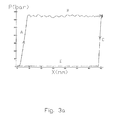
- FIG. 3 a is a diagram showing the pressure as a function piston stroke of data as measured in a triplex pump
- FIG. 3 b shows an enlarged view of the compression and the decompression phases from the diagram in 3 a;
- FIG. 4 shows in a perspective view a mud pump according to prior art, to which the pressure sensing device described herein has been incorporated;
- FIG. 5 shows in a front view the valve blocks of the mud pump from FIG. 4 having the incorporated pressure sensing device shown;
- FIG. 6 shows a cross section of the valve blocks and pressure sensing device from FIG. 5 as seen through the line A-A of FIG. 5 .
- the disclosure relates to an apparatus for measuring the compressibility of a fluid being circulated by a positive displacement pump, the apparatus comprising:
- fluid module is meant both the chamber in which the fluid is being compressed/decompressed as well as any the clearance volume.
- the positive displacement pump may be a reciprocating piston pump, wherein the fluid displacing member is a piston, and wherein the fluid module comprises the cylinder itself and the clearance volume.
- plunger pump shall be construed to also include plunger pumps.
- the control unit may be any type of computer, such as a programmable logic controller, a microcontroller or the like. It may be communicating with the sensing devices wirelessly or through cables or other conductors, as will be known to a person skilled in the art.
- Compressibility which is the inverse of the bulk modulus, of a fluid is defined as the ratio of relative volume decrease to change in pressure, in mathematical terms
- V is the confined fluid volume and P is the fluid pressure.
- V max represents the maximum volume between the piston and the closed valves
- A is the cross-sectional area of the piston seal.
- the residual volume is often called the clearance volume.
- the piston stroke can be measured either directly by a suitable linear motion sensor such as a linear variable differential transformer, or indirectly by measuring the angular position of the crank shaft or the cam driving the piston.
- X (1 ⁇ cos ⁇ ) R + ⁇ square root over ( L 2 ⁇ ( R sin ⁇ ) 2 ) ⁇ ⁇ L (3)
- R is the crank shaft radius (half the nominal piston stroke)
- L is the effective crank rod length
- ⁇ is the crank shaft angle, referred to the start of the pumping phase.
- the fluid compressibility can therefore be interpreted as the slope of the curve representing ⁇ ln(V) versus pressure P or, alternatively, as the derivative of a fit function matching ⁇ ln(V) versus P.
- the compressibility is fairly constant in the pressure range typically experienced when drilling oil or gas wells.
- the non-linearity should not be neglected, meaning that the compressibility changes significantly with pressure.
- K 1 and K 2 are called 1 st and 2 nd order compressibility, respectively.
- the latter is often negative and of the same order of magnitude as the first order compressibility.
- Density and the compressibility factors are, in general, temperature dependent. Therefore, a precise calculation of the density and the hydrostatic pressure in a well may include thermal expansion effects. It is, however beyond the scope of this document to discuss thermal effects, other than stating that the fluid temperature may preferably be measured also during the described compressibility measurement procedure.
- control unit may be adapted to log the pressure of the confined volume and the position of the piston at a rate of at least 100 times the rotation frequency of the positive displacement pump. This may enable sufficient loggings in the compression or decompression phase to obtain two or three reliable loggings within the compression and/or decompression phase of the pump in order to be able to calculate the compressibility.
- the maximum rotation frequency of a positive displacement pump such as a reciprocating piston pump, may be in the range of 100-300 rpm, thus requiring logging rates of at least 100-300 Hz.
- the pressure sensing device may be adapted to sample the pressure of the confined fluid at a sampling rate of at least 1 kHz.
- sensing devices should preferable have a higher sampling rate than the desired logging rate.
- the sampling rate should be in the range of 10 times the desired logging frequency. A logging frequency of 100 Hz would therefore require a sampling frequency of 1 kHz or above.
- the pressure sensing device 5 may be a commercially available pressure transmitter, such as a PTX 661 Druck Hammer Union pressure transmitter.
- control unit when calculating the compressibility of the confined fluid, may further be adapted to exclude logged data when the pressure of the confined fluid is lower than a pressure P lo .
- P lo a pressure
- the control unit when calculating the compressibility of the confined fluid, may further be adapted to exclude logged data when the pressure of the confined fluid is lower than a pressure P lo .
- control unit when calculating the compressibility of the fluid, may be adapted to exclude logged data when the pressure of the confined fluid is higher than a pressure P hi .
- control unit may be adapted to use regression analysis of the logged data to find the fluid compressibility.
- the control unit when calculating a volume of the fluid, may further be adapted to account for volume changes in the positive displacement pump itself.
- the volume changes which may be pressure-induced elastic deformations of the pump, including ballooning of the liner and elastic shortening of the piston rod, may be taken into account for improving the accuracy of the calculated compressibility.
- the apparatus may further comprise a temperature sensing device for sensing the temperature of the fluid in or near the positive displacement pump.
- the temperature measurements may be taken at the inlet or at the outlet of the fluid pump.
- the fluid compressibility is, as described above, a temperature-dependent parameter.
- the temperature sensing device should be regarded as an optional feature.
- the mud pump may be any kind of reciprocating pumps commonly used in the oil and gas industry, such as Triplex pumps, Quintuplex pumps or Hex pumps.
- the disclosure relates to a method for measuring the compressibility of a fluid being circulated by a positive displacement pump by means of an apparatus according to claim 1 of the present application, wherein the method comprises the following steps:
- the method may further comprise sensing the temperature of the fluid in or near the positive displacement pump.
- the method may comprise one or more of following steps:
- the sampling rate may be, as described above, at least 1000 times faster than the highest pump rotation frequency, because the compression and decompression phases represent relatively small fractions of the pump cycle and the regression analysis requires many samples in order to provide statistically robust results.
- the elastic deformation correction term can be found either theoretically from detailed knowledge of the pump geometry, or it can be found experimentally from a calibration test where a fluid, with an a priori known compressibility, is used.
- the validity check of the derived compressibility parameters could also include the measured compressibility from preceding pump rotations, from other instrumented fluid modules in the same pump, from other pumps pumping the same fluid and/or from consistency between compression and decompression based compressibility estimates.
- a systematic discrepancy between values derived for the compression and decompression phases, transition phases for short, is an indication that the total volume, is not correct. If the volume is not determined accurately from the internal fluid module geometry of the fluid module, it could be determined experimentally by requiring that the two compressibility estimates match.
- reference numeral 1 refers to an apparatus according to the present disclosure. Identical reference numerals indicated identical or similar features in the figures.
- FIG. 1 an apparatus 1 according to the present disclosure is shown schematically and incorporated into a positive displacement pump 10 in the form a reciprocating piston pump.
- a fluid module 2 here shown as one simple cylinder, is fluidly connected to an inlet 21 and to an outlet 23 .
- a suction valve 27 is provided at the inlet 21 while a discharge valve 29 is provided at the outlet 23 .
- a fluid displacing member in the form of a piston 25 with a piston shaft 24 is sealingly and reciprocally displaceable in the fluid module 2 by means of a drive unit 3 .
- the piston 25 while being displaced inwardly in the fluid module 2 , compresses the fluid confined fined in the fluid module 2 of the reciprocating pump 10 so as to increase the pressure of the fluid.
- the pressure will be increased up to a level where the discharge valve 29 is opened and mud is discharged from the fluid module 2 through the outlet 23 .
- the mud is decompressed. Below a certain pressure level, the suction valve 27 will open and mud will flow into the fluid module 2 through the inlet 21 .
- a position sensing device 7 is shown in the form of a position sensor measuring the position of the piston shaft 24 and thereby the piston 25 . By knowing the geometry and the clearance volume of the fluid module 2 , the volume V of the mud in the fluid module 2 can be calculated by means of a not shown control unit connected to the position sensor 7 by measuring the exact position of the piston 25 as described in the general part of the description.
- a pressure sensing device 5 is provided in the fluid module 2 .
- the pressure sensing device 5 is adapted to measure the pressure P of the mud in the fluid module 2 at any position of the piston 25 , and transmit the sensed pressure P to the not shown control unit.
- pressure sensing device 5 may also be described as a pressure transmitter.
- FIG. 2 A somewhat simplified example of a curve showing the pressure P of the fluid as a function of the position X of the piston 25 is shown in FIG. 2 .
- the piston 25 In a phase A of the curve, the piston 25 is compressing the fluid. In this simplified example, the compression entails a steadily and linearly increasing pressure P of the fluid.
- the discharge valve 29 At an abrupt transition T between phase A and a phase B on the curve, the discharge valve 29 is opened while the piston 25 is still being moved inwardly in the fluid module 2 .
- T′ between phase B and a phase C, the piston 25 starts moving outwardly/retracting in the fluid module 2 , thus decompressing the confined fluid.
- the pressure P is steadily and linearly decreasing in phase C.
- phase C The steeper slope of phase C compared to phase A will be explained with reference to FIGS. 3 a and 3 b below.
- T′′ the suction valve 27 opens, and the pressure P remains constant in phase D, the suction phase, on the curve as the piston 25 is further retracted while the suction valve 27 remains open.
- the cycle starts over again at a fourth abrupt transition T′′′ between phase D and phase A.
- the position X of the piston 25 is calculated into the volume V of the mud in the fluid module 2 , and the compressibility K of the mud can be calculated as described in the general part of the description.
- Phases A and C of this simplified curve can be used to perform a linear fit to find the compressibility K of the mud.
- phases A and C may be non-linear as have already been discussed in the general part of the description and will be described with reference to FIGS. 3 a and 3 b below, and higher order fits may be needed to find the compressibility of the fluid.
- FIG. 3 a shows a cylinder pressure P in bars versus piston stroke X in millimeter recorded in a triplex mud pump.
- the up- and down arrows in phases A and C indicate, as in FIG. 2 , the compression and decompression phases, respectively, suitable for compressibility estimation.
- the relatively constant high and low level pressure parts in phases B and D of the curve represent pumping and suction phases of the pump 10 , respectively, where one of the valves is open.
- the non-constant discharge pressure P disch is due to pressure variations in a piping system to which the Triplex pump is connected as will be understood by a person skilled in the art.
- the pressure drop in the decompression phase C is steeper than the pressure increase in the compression phase A, which is at least partly due to the fact the whole volume of the fluid module is compressed in phase A, whereas only the clearance volume is decompressed in phase C.
- FIG. 3 b A zoom-in or enlarged plot of the compression and decompression phases A, C is shown in FIG. 3 b .
- the linear compression phase starts slightly after the piston 25 turns and the pressure P has reached a value P lo of roughly 20 bar.
- This delayed start of the compression phase is due to valve inertia and piston seal compression.
- Valve inertia causes the discharge valve 29 to close slightly after the piston 25 has passed its datum position, and a cushion effect of the piston seal slows down the fluid compression until there is metal to metal contact between the valve and the valve seat.
- the resulting low slope part of the compression curve may therefore preferably be excluded from the data used for determining the compressibility K.
- the analysis may exclude pressure data exceed an upper pressure threshold P hi , typically equal to the mean discharge pressure P disch minus lower pressure threshold P lo .
- P hi typically equal to the mean discharge pressure P disch minus lower pressure threshold P lo .
- An additional benefit of excluding the lowest pressures in the compressibility calculations is that the disturbing effect of a possible small gas or foam content in fluid will be minimized. As an example, if the gas volume content is 1% at ambient atmospheric pressure, the gas volume has decreased to approximately 0.05% at 20 bar. This is far less than the true fluid compression volume, meaning that the gas will not influence the calculated fluid compressibility significantly.
- FIG. 4 shows a positive displacement pump 10 in the form of a triplex mud pump 10 according to prior art.
- the shown pump 10 is, minus the pressure transmitter 5 , commercially available from the present applicant, and its function and construction will be known to a person skilled in the art and will therefore not be described in detail herein.
- the triplex mud pump 10 comprises a drive unit 3 connected via not shown cranks to three positive displacements/plungers 25 in cylinders.
- the position of at least one of the pistons 25 may, according to the present disclosure, be measured by a position sensor 7 , not shown in the figure.
- An inlet 21 in the form of a manifold is fluidly connected to the cylinders through suction valves 27 included in valve blocks 11 .
- the cylinders are fluidly connected to an outlet 23 , also in the form of a manifold, through discharge valves 29 in the valve blocks 11 .
- valve blocks 11 Details of the valve blocks 11 , including suction valves 27 and discharge valves 29 , are shown in FIGS. 5 and 6 .
- the cylinders and the valve blocks 11 are included in the fluid module 2 of the triplex pump.
- the pressure transmitter 5 is shown connected to the mid valve block 11 . In alternative embodiments, the pressure transmitters 5 can additionally or alternatively be connected to other parts of the fluid module 2 .
Landscapes
- Engineering & Computer Science (AREA)
- Life Sciences & Earth Sciences (AREA)
- Geology (AREA)
- Mining & Mineral Resources (AREA)
- Physics & Mathematics (AREA)
- Environmental & Geological Engineering (AREA)
- Fluid Mechanics (AREA)
- General Life Sciences & Earth Sciences (AREA)
- Geochemistry & Mineralogy (AREA)
- Chemical & Material Sciences (AREA)
- Mechanical Engineering (AREA)
- Health & Medical Sciences (AREA)
- Oil, Petroleum & Natural Gas (AREA)
- Biochemistry (AREA)
- Chemical Kinetics & Catalysis (AREA)
- General Engineering & Computer Science (AREA)
- Food Science & Technology (AREA)
- Medicinal Chemistry (AREA)
- Analytical Chemistry (AREA)
- General Chemical & Material Sciences (AREA)
- General Health & Medical Sciences (AREA)
- General Physics & Mathematics (AREA)
- Immunology (AREA)
- Pathology (AREA)
- Measuring Fluid Pressure (AREA)
- Other Investigation Or Analysis Of Materials By Electrical Means (AREA)
- Control Of Positive-Displacement Pumps (AREA)
- Details Of Reciprocating Pumps (AREA)
Abstract
Description
-
- a pressure sensing device for sensing a pressure of a fluid confined in a fluid module of the positive displacement pump;
- a position sensing device for sensing the position, directly or indirectly, of a fluid displacing member in the fluid module of the positive displacement pump, wherein the apparatus further comprises a control unit communicating with said pressure sensing device and said position sensing device, the control unit being adapted to:
- log said pressure and said piston position substantially synchronously;
- by means of the logged position of the fluid displacing member calculate a volume of the confined fluid in the fluid module of the positive displacement pump; and
- by means of the logged pressure and the calculated volume, calculate the compressibility of the fluid.
V=V max A·X (2)
X=(1−cos θ)R+√{square root over (L 2−(R sin θ)2)}−L (3)
K=K 1+2K 1 K 2 P (4)
V=V oexp(K 1 P+K 1 K 2 P 2) (5)
ρ=ρoexp(K 1 P+K 1 K 2 P 2) (6)
ρ=ρo·(1+K+(0.5K 1 +K 2)K 1 P 2) (7)
-
- by means of the pressure sensing device, sensing the pressure of a fluid confined in a fluid module of the positive displacement pump;
- by means of the position sensing device, sensing the position, directly or indirectly, of a piston in the fluid module of the positive displacement pump;
- by means of a control unit logging the sensed pressure and position substantially synchronously;
- by means of the logged position of the piston calculating a volume of the fluid confined in the fluid module of the reciprocating pump; and
- by means of the logged pressure and the calculated volume calculating the compressibility of the fluid.
-
- 1. Measure and record at a high sampling rate cylinder pressure P and angular position θ of a pump crank shaft or cam;
- 2. Calculating a linear piston position X and the corresponding fluid volume V from the angular pump position θ;
- 3. Determine a low pressure limit, Plo, beyond which a piston seal is completely compressed and a corresponding high pressure limit, Phi=Pdisch−Plo beyond which one of the valves are partially or fully open, wherein Pdisch is the discharge pressure of the reciprocating pump;
- 4. Selectively pick the compression phase data satisfying the logical function (P>Plo) & (P<Phi) & (X<Xlo), where Xlo representing maximum compression stroke;
- 5. Calculate the help function defined as Y=−ln(V) and apply regression analysis to the picked data set to find a 2nd order polynomial fit function Yfit=a0+a1P+a2P2;
- 6. Find the fluid compressibility as the derivative of this fit function and determine the first and second order compressibility as K1=a1−as and K2=a2/K1, respectively. Here as is a correction term accounting for pressure induced, elastic deformation of the pump, as explained above;
- 7. Accept the compressibility measurement as valid if K1 and K2 are close to their expected values. On the contrary, discard results and flag a possible leak or malfunction of the valves or piston seals; and
- 8. Repeat the analysis for the decompression phase data, satisfying (P>Plo) & (P<Phi) & (X>Xhi), where Xhi represents maximum decompression stroke, typically Xmax−Xlo.
Claims (20)
Applications Claiming Priority (1)
| Application Number | Priority Date | Filing Date | Title |
|---|---|---|---|
| PCT/NO2013/050111 WO2014204316A1 (en) | 2013-06-19 | 2013-06-19 | Method and apparatus for real-time fluid compressibility measurements |
Publications (2)
| Publication Number | Publication Date |
|---|---|
| US20160138393A1 US20160138393A1 (en) | 2016-05-19 |
| US9915147B2 true US9915147B2 (en) | 2018-03-13 |
Family
ID=52104939
Family Applications (1)
| Application Number | Title | Priority Date | Filing Date |
|---|---|---|---|
| US14/897,345 Active US9915147B2 (en) | 2013-06-19 | 2013-06-19 | Method and apparatus for real-time fluid compressibility measurements |
Country Status (5)
| Country | Link |
|---|---|
| US (1) | US9915147B2 (en) |
| BR (1) | BR112015031215B1 (en) |
| CA (1) | CA2916067C (en) |
| NO (1) | NO346823B1 (en) |
| WO (1) | WO2014204316A1 (en) |
Families Citing this family (8)
| Publication number | Priority date | Publication date | Assignee | Title |
|---|---|---|---|---|
| EP2998016A1 (en) * | 2014-09-17 | 2016-03-23 | Fast&Fluid Management B.V. | Assembly for and method of dispensing a liquid |
| EP3144643A1 (en) * | 2015-09-18 | 2017-03-22 | Geoservices Equipements | A method for estimating a flow out of a fluid pump, associated calculation system and associated drilling installation |
| WO2017058161A1 (en) * | 2015-09-29 | 2017-04-06 | Halliburton Energy Services, Inc. | Bulk modulus monitoring system |
| GB2551141B (en) * | 2016-06-07 | 2020-05-13 | Equinor Energy As | Method and system for managed pressure drilling |
| US11499544B2 (en) | 2016-08-31 | 2022-11-15 | Halliburton Energy Services, Inc. | Pressure pump performance monitoring system using torque measurements |
| EP3486482B1 (en) | 2017-11-17 | 2021-12-08 | Artemis Intelligent Power Limited | Measuring hydraulic fluid pressure in a fluid-working machine |
| IT202100014633A1 (en) * | 2021-06-04 | 2022-12-04 | Camozzi Automation S P A | PRESSURE MULTIPLIER |
| CN120402347B (en) * | 2025-07-01 | 2025-09-05 | 东营市道尔工贸有限责任公司 | A mud pump experimental device |
Citations (9)
| Publication number | Priority date | Publication date | Assignee | Title |
|---|---|---|---|---|
| US4255088A (en) * | 1979-06-14 | 1981-03-10 | Valleylab, Inc. | Liquid pumping system having means for detecting gas in the pump |
| US5635631A (en) | 1992-06-19 | 1997-06-03 | Western Atlas International, Inc. | Determining fluid properties from pressure, volume and temperature measurements made by electric wireline formation testing tools |
| US6176323B1 (en) * | 1997-06-27 | 2001-01-23 | Baker Hughes Incorporated | Drilling systems with sensors for determining properties of drilling fluid downhole |
| US6832515B2 (en) * | 2002-09-09 | 2004-12-21 | Schlumberger Technology Corporation | Method for measuring formation properties with a time-limited formation test |
| US7234521B2 (en) * | 2003-03-10 | 2007-06-26 | Baker Hughes Incorporated | Method and apparatus for pumping quality control through formation rate analysis techniques |
| US20090165548A1 (en) | 2007-12-31 | 2009-07-02 | Julian Pop | Systems and methods for well data analysis |
| EP2430309A1 (en) | 2009-04-30 | 2012-03-21 | Agilent Technologies, Inc. | Determining fluid compressibility while delivering fluid |
| US20130243028A1 (en) * | 2010-08-26 | 2013-09-19 | Schlumberger Technology Corporation | Apparatus and method for phase equilibrium with in-situ sensing |
| US20150127262A1 (en) * | 2012-06-21 | 2015-05-07 | Halliburton Energy Services, Inc. | Method and apparatus for formation tester data interpretation with diverse flow models |
-
2013
- 2013-06-19 WO PCT/NO2013/050111 patent/WO2014204316A1/en not_active Ceased
- 2013-06-19 NO NO20151610A patent/NO346823B1/en unknown
- 2013-06-19 US US14/897,345 patent/US9915147B2/en active Active
- 2013-06-19 CA CA2916067A patent/CA2916067C/en active Active
- 2013-06-19 BR BR112015031215-2A patent/BR112015031215B1/en active IP Right Grant
Patent Citations (9)
| Publication number | Priority date | Publication date | Assignee | Title |
|---|---|---|---|---|
| US4255088A (en) * | 1979-06-14 | 1981-03-10 | Valleylab, Inc. | Liquid pumping system having means for detecting gas in the pump |
| US5635631A (en) | 1992-06-19 | 1997-06-03 | Western Atlas International, Inc. | Determining fluid properties from pressure, volume and temperature measurements made by electric wireline formation testing tools |
| US6176323B1 (en) * | 1997-06-27 | 2001-01-23 | Baker Hughes Incorporated | Drilling systems with sensors for determining properties of drilling fluid downhole |
| US6832515B2 (en) * | 2002-09-09 | 2004-12-21 | Schlumberger Technology Corporation | Method for measuring formation properties with a time-limited formation test |
| US7234521B2 (en) * | 2003-03-10 | 2007-06-26 | Baker Hughes Incorporated | Method and apparatus for pumping quality control through formation rate analysis techniques |
| US20090165548A1 (en) | 2007-12-31 | 2009-07-02 | Julian Pop | Systems and methods for well data analysis |
| EP2430309A1 (en) | 2009-04-30 | 2012-03-21 | Agilent Technologies, Inc. | Determining fluid compressibility while delivering fluid |
| US20130243028A1 (en) * | 2010-08-26 | 2013-09-19 | Schlumberger Technology Corporation | Apparatus and method for phase equilibrium with in-situ sensing |
| US20150127262A1 (en) * | 2012-06-21 | 2015-05-07 | Halliburton Energy Services, Inc. | Method and apparatus for formation tester data interpretation with diverse flow models |
Non-Patent Citations (2)
| Title |
|---|
| Article 19 Amendments to PCT/NO2013/050111 dated Oct. 14, 2015 (2 pages). |
| Written Opinion for PCT/NO2013/050111 dated Mar. 28, 2014 (6 pages). |
Also Published As
| Publication number | Publication date |
|---|---|
| NO346823B1 (en) | 2023-01-16 |
| CA2916067A1 (en) | 2014-12-24 |
| CA2916067C (en) | 2021-06-08 |
| NO20151610A1 (en) | 2015-11-25 |
| BR112015031215B1 (en) | 2021-10-13 |
| WO2014204316A1 (en) | 2014-12-24 |
| BR112015031215A2 (en) | 2017-07-25 |
| US20160138393A1 (en) | 2016-05-19 |
Similar Documents
| Publication | Publication Date | Title |
|---|---|---|
| US9915147B2 (en) | Method and apparatus for real-time fluid compressibility measurements | |
| US11105706B2 (en) | Hydrostatic and vibration test method for a blowout preventer | |
| CN104185735B (en) | Fluid load curve calculation, concavity test and iterative damping factor for downhole pump card | |
| US7500390B2 (en) | Method for estimating pump efficiency | |
| US8366402B2 (en) | System and method for determining onset of failure modes in a positive displacement pump | |
| US11111772B2 (en) | Bulk modulus monitoring system | |
| US10859082B2 (en) | Accurate flow-in measurement by triplex pump and continuous verification | |
| JP6875053B2 (en) | Methods and equipment for determining the production of downhaul pumps | |
| CA3116804A1 (en) | System and method for operating downhole pump | |
| CN107917069B (en) | Reciprocating compressor flow sensing | |
| NO346114B1 (en) | Estimating flow rate at a pump | |
| WO2017180839A1 (en) | Sucker rod pumping unit and method of operation | |
| US10876941B2 (en) | Determining fluid density in a pressure pump using bulk modulus measurements | |
| KR101750405B1 (en) | Method and apparatus for testing drifter of rock-driller | |
| US20150142321A1 (en) | Flow Rate From Displacement Unit Piston Position |
Legal Events
| Date | Code | Title | Description |
|---|---|---|---|
| AS | Assignment |
Owner name: NATIONAL OILWELL VARCO NORWAY AS, NORWAY Free format text: ASSIGNMENT OF ASSIGNORS INTEREST;ASSIGNORS:KYLLINGSTAD, AGE;AUSTEFJORD, ARNE;REEL/FRAME:037260/0108 Effective date: 20151210 |
|
| STCF | Information on status: patent grant |
Free format text: PATENTED CASE |
|
| MAFP | Maintenance fee payment |
Free format text: PAYMENT OF MAINTENANCE FEE, 4TH YEAR, LARGE ENTITY (ORIGINAL EVENT CODE: M1551); ENTITY STATUS OF PATENT OWNER: LARGE ENTITY Year of fee payment: 4 |
|
| AS | Assignment |
Owner name: NOV INTERNATIONAL HOLDINGS C.V., CAYMAN ISLANDS Free format text: ASSIGNMENT OF ASSIGNORS INTEREST;ASSIGNOR:NATIONAL OILWELL VARCO NORWAY AS;REEL/FRAME:064367/0415 Effective date: 20220326 |
|
| AS | Assignment |
Owner name: GRANT PRIDECO, INC., TEXAS Free format text: ASSIGNMENT OF ASSIGNORS INTEREST;ASSIGNOR:NOV INTERNATIONAL HOLDINGS C.V.;REEL/FRAME:063888/0818 Effective date: 20220327 |
|
| MAFP | Maintenance fee payment |
Free format text: PAYMENT OF MAINTENANCE FEE, 8TH YEAR, LARGE ENTITY (ORIGINAL EVENT CODE: M1552); ENTITY STATUS OF PATENT OWNER: LARGE ENTITY Year of fee payment: 8 |