US991111A - Electrical system of distribution. - Google Patents
Electrical system of distribution. Download PDFInfo
- Publication number
- US991111A US991111A US1909479755A US991111A US 991111 A US991111 A US 991111A US 1909479755 A US1909479755 A US 1909479755A US 991111 A US991111 A US 991111A
- Authority
- US
- United States
- Prior art keywords
- train
- various
- conductor
- units
- generator
- Prior art date
- Legal status (The legal status is an assumption and is not a legal conclusion. Google has not performed a legal analysis and makes no representation as to the accuracy of the status listed.)
- Expired - Lifetime
Links
Images
Classifications
-
- H—ELECTRICITY
- H02—GENERATION; CONVERSION OR DISTRIBUTION OF ELECTRIC POWER
- H02J—ELECTRIC POWER NETWORKS; CIRCUIT ARRANGEMENTS OR SYSTEMS FOR SUPPLYING OR DISTRIBUTING ELECTRIC POWER; SYSTEMS FOR STORING ELECTRIC ENERGY
- H02J7/00—Circuit arrangements for charging or discharging batteries or for supplying loads from batteries
- H02J7/50—Circuit arrangements for charging or discharging batteries or for supplying loads from batteries acting upon multiple batteries simultaneously or sequentially
- H02J7/575—Parallel/serial switching of connection of batteries to charge or load circuit
Definitions
- My invention relates to electrical systems of distribution and is more especially designed with respect to electrical train lighting systems in which a plurality of feeding conductors extend through the various train units to properly feed the translating.
- a plurality of feeding conductors extend through the various train units to properly feed the translating.
- it is customary to provide one generator and a separate storage battery and lighting or work circuit on each one of the various train units.
- the purpose of the battery is. to pro- "vide a source of electrical energy for feeding the lamps or other translating devices when the generator is shut down.
- My invention also comprehends the provision of a system which, is economical andefficient in operation and construction and which has many minor advantages.
- A, B and 0 represent three train units, of which the unit A may be the locomotive or baggage car upon which the main generator 1 is situated.
- the units B and C represent cars or coaches carrying the lighting or work'ci-rcuits 2, 2.
- Each car ' is also provided with a storage battery 3, 3.
- a feeding conductor 4' which connects the positive side of the generator 1 with the various circuits 2,'by means of connectors 5, 5.
- a conductor 6 which connects the positive side of the generator 1 with the various batteries by means of connectors 7.
- the conductor 6, therefore, acts as a charging conductor for the purpose of conveying the charging current to the batteries 3, 3.
- a booster 8 in series with the conductor 6, also extending throughout the various train units is a conductor 9 which connects with the negative terminal of the generator 1.
- the booster 8 is provided with a controlling field coil 14 energized by a counterelectromotive .force exciter 15 which is controlled in the usual manner'by a field coil tions are made by 16 connected in shunt to the resistance 17
- the exciter 15 and booster 8 are driven by a motor 18 in the usual manner.
- Each of the units B and C is provided with an electro-responsive switch 19 which in its lower position connects the battery 3 directly across the work circuit 2 by electrically connecting the terminals 20.
- the switch 19 When the switch 19 is in its uppermost position the connection between the terminals 20 is broken and said switch makes electrical connection between the contact terminals 21, 21, so that the battery .is connected directly to the charging conductor 6.
- switch 19 is also provided with a blade 23 which when in its uppermostposition electrically connects contact terminals 24 to connect the various work circuits directly wit-h the feed ing conductor 4.
- the 25 represents a'switch arranged to connect the terminals 27, 27 so as to complete a circuit 28 which includes a magnet coil 29 operating upon a switch 30 when the switch 25 is in its lowermost position.
- the switch 25 When the switch 25 is in its uppermost position it connects terminals 31, 31, which completes a circuit 32 in series with the magnet coil 33 which also operates upon the switch 30 but in the opposite direction from the magnetcoil 29.
- the switch 25 is maintained in its lowermost position by gravity and is arranged to be drawn upward by means of the magnet coil 34 connected across the conductors 4 and 9 so as to be responsive to the voltage of the main generator 1.
- the switch 25 when the switch 25 is lowered the coil 29 is energized, being connected between the conductors ,9 and 6, and when the switch 25 is raised under the action of coil 34 the coil 33 is energized, being also connected across the conductors 9 and C.
- the switch 30 Upon the energization of coil 33 the switch 30 is raised, thus making electrical connection between the contact terminals 35 and 36 so as to connect that portion of the feeding conductor 4 upon .the unit A with that portion of the feeding conductor 4 on the various other train units.
- the switch 25 is in its lowermost position the coil 33 is 29 is energized so that the switch 30 is pulled down, thus opening the circuit throu h the conductor 4so that it isno longer ed by the generator 1.
- the switches 19 on the units B and O are arranged to be drawn upward in order to connect the batteries with the charging conductor 7 and the work circuits with the feeding conductor 4 by means of magnet coils 39, one terminal of which is connected to the negative conductors 12 by means of wires 40 and the other terminal of which is connected to a contact 41.
- the magnet coils 39 and 48 act in opposite directions upon the switches 19, the coils 39 operating to raise the switches and the coils 48 operating to drop the switches.
- the switches 42 are controlled by means of magnet coils 49 which are connected between the positive conductor 4 and the negative conductor 10 by a circuit 50.
- 51 and 52 are switches which are in series with the coils 39 and 48 respectively.
- the system as represented shows the various parts in the position they would keep when the main generator 1 is shut down or is practically inoperative.
- the generator 1 When the generator 1 is started up and produces a predetermined voltage the coil 34 acts upon the switch 25 to attract the same, thereby connecting contact terminals 31 and energizing the magnet coil 33 of switch 30.
- This causes the switch 30 to be attracted upwardly to connect the contact terminals 35 and 36' so that the circuit through the train conductor 4 is completed and extends through the various units B and C and be comes energized.
- the coils 49 become energized so that the switches 42 are attracted upwardly to connect the contact terminals 41 and 43, thus completing the circuit through the magnet coils 39 to energize the same.
- This .action denergizes the various voltage coils 49, '49, which operate the switches 42 so that these switches are dropped to their lowermost position, thereby opening the circuit 39, 39 and closing the circuit through the magnet coils 48, 48 of the main switches 19 so that the switches 19 are attracted to their lowermost positions in which the blades 22 thereof connect the terminals 20 so that the batteries 3 are connected to the work circuit 2 and are wholly and entirely disconnected from both the positive conductors, namely, the charging conductor 6 and the feeding conductor 4.
- the small hand switches 60 which I have shown as bridging the contacts 24, 24, may be closed, so that if desirable, all the batteries may be charged in parallel in the yards when the unit on which the generator is placed is disconnected, in which case a separate source of electromotive force would be applied to the conductors 4 and 10. Also upon failure of the generator in service the batteries may be thus connected to jointly supply the load with the generator.
- a generator feeding conductor for the various work circuits extending through the various train units, a charging, conductor for the batteries extending through the various train units, a common return conductor for the batteries and-work circuits, and means responsive to a decrease in the generator voltage for rendering said batteries disconnected from various of said conductors to render all-of said conductors dead.
- a generato on one train unit a plurality of batteries and work circuits on other train units, a feeding conductor for the various work circuits extending through the various train units, a charging conductor for the batteries extending through the various train batteries and work circuits, and means for disconnecting the batteries from all the conductors which are normally connected to one side of the genera-tor responsive to a decrease in the voltage of the generator.
- a source of electromotive force a battery and work circuit arranged to be fed thereby, conductors for connecting the battery and work circuit with said source, a switch member in series with the work circuit for opening the conductor leading to the work circuit from the source, a switch member in series with the battery for'opening the conductor leading to the battery, and means for actuating said members responsive to variations in the electrical condition of the system.
- a source of electromotive force a plurality of'batteries and work circuits arranged to be fed thereby, conductors for connecting the batteries and work circuits with said source, a switch member in series with each work circuit for opening the conductor leading to each work circuit from the source, a switch member in series with each battery for opening the conductor leading to each battery, and means for actuating said members responsive to variations in the electrical condition of the system.
- a storage battery and work circuit on each of the other units a feeding conductor extending through the various units and connected to the various work circuits, a charging conductor extending through the various units andconnected to the various abatteries to charge the same, a common return conductor extending through the various train units-and connected to the various batteries and work circuits and means for independently disconnecting the batteries and work circuits on each unit from all of said conductors of one polarity responsive to a. decrease in generator voltage.
- a plurality of train units a generator on the train, a storage battery and work circuit on each of the units, a feeding train conductor extending from the generator through the various train units and feeding the various work circuits, a charging train conductor extending through the various train units and connected to the batteries for charging the same, a return train conductor for the batteries and work circuits extending through the various train units, and means for disconnectingthe battery and work circuit 011 each unit from said feeding and charging conductors responsive to a change in the electrical condition of the system.
- a plurality of train units a generator on the 1 train, a storage battery and work circuit on each of the units, a feeding train conduct-or extending from the generator through the various train units and feedin the various work circuits, a charging train conductor extending through the various train units and connected to the batteries for charging the same, a return train conductor for the batteries and work circuits extending extending through the various train units and connected to the batteries for ohargin the same, a' return train conductor for the batteries and work circuits extending through the various train units, a switch on various units for disconnecting the batteries and work circuits thereon from said charging and feeding conductors and a solenoid on said units for controlling the action of said switches responsive to the electrical condition of the generator.
- a plurality'of train units a storage battery and work circuit on each of the units, a generator, a feeding train conductor extending from the enerator through the various train units an feeding the various work circuits, a charging train conductor extending through the various train units and connected to the batteries for charging the same, a return train conductor for the batteries and work circuits extending through the various train units, a switch on each unit with the batteries and work circuits for wholly disconnecting the battery thereon from the charging and feeding conductors and a coil responsive to generator voltage for controllingthe action of said switches.
- a plurality of train units a storage battery and work circuit on each of the units, a generator, a feeding train conductor extending from the generator through the various train units and feeding the various work circuits, a charging train conductor extending through the various train units and connected to the batteries for charging the same, a return train conductor for the batteries and work circuits extending through the various train units, a switch for opening one of said conductors between the generator and one of the work circuits and batteries, switches on various units for wholly discon- 1 necting the batteries thereon from said feeding and charging conductors and a coil responsive to the action of said first mentioned switch for controlling the action of said last mentioned switches responsive thereto.
- a plurality of train units In an electrical system of distribution, a plurality of train units, a storage battery and Work circuit on each of the units, a generator, a feeding train conductor extending from the generator through the various 13 -between' the feeding conductor and the return conductor, and switches on various of the train unitsfor disconnecting the batteries and work circuits from said feeding and char 'ng conductors, said switches being controlle by-said coils.
- a generator In a system of electrical distribution, a generator, a plurality of train units each carryin a work circuit'and a storage battery, a eeding conductor extending throu h the various train units for connecting the work circuits with the generator, a charging conductor extending through the various train units for charging the batteries, a booster in said circuit a common return conductor extending through the various train units to the generator, a switch for opening the feeding circuit to disconnect the generator from the work circuits, a switch for controlling the action of said last mentioned switch responsive to the generator voltage and the generator current and means for renderin the various conductors on the train units dead responsive to the opening of said first mentioned switch.
- a generator Ina system of electrical distribution, a generator, :1 lurality of train units each carryin a wor circult and a storage battery, a eeding conductor extending through the various train units for connecting the I work circuits with the generator, a charging conductor extending through the various train units for charging the batteries, a
- booster'in said circuit a common return conductor extending through the various'train units to the generator, a switch for opening the feeding circuit to disconnect the meretor from the work circuits, a switch fbr controlling the action of said last mentioned switch responsive to the generator voltage and the generator current and means for rendering the various conductors on the train units dead responsive to the opening of said first mentioned switch, said means including switches on each car for disconnecting the battery and work circuit thereon from the feeding and charging conductors.
- a plurality of train units a generator, a storage battery and work circuit on each of the units, a feeding train conductor extending from the generator through the various train units and feeding the various work circuits, a charging train conductor extending through the various train units and 'connected to the batteries for charging the same a return train conductor for the batteries and work circuits extending through the various train units, and means for rendering said conductors dead responsive to a shutdown of the generator.
- a work circuit a battery, a feeding conductor for the work circuit, a charging conductor for the battery, a common return conductor and a switch apparatus for automatically and wholly disconnecting the battery and workcircuit from said charging and feeding conductors responsive to a drop in voltage across the feeding and return conductors, said switch apparatus being provided with two coils, each operating upon it to cause it to move in the opposite "direction from other coil causes it to move;
- a plurality of train units a battery and work circuit on each unit, a source ofelectrical energy, a plurality of conductors leading from said source through said units for feeding the batteries and work circuits, means for disconnecting the source from said conductors responsive to condition of the system and means for disconnectin each battery from all of said conductors 0 one polarity to render all of said conductors dead, responsive to a change in the electrical condition of the system.
Landscapes
- Engineering & Computer Science (AREA)
- Power Engineering (AREA)
- Charge And Discharge Circuits For Batteries Or The Like (AREA)
Description
15 vices thereon.
50 not UNITED STATES PATENT OFFICE.
WILLIANfA. TITRBAYNE, or LANCASTER, new 20mg, ASSIGNOR 'ro" eoum courier.
-. comranx, A conrom'rron orgnnw YORK.
F nmc'rmoai. SYSTEM or" ms'rninurron.
Specification of Letters Patent.
Patented May 2 Application flledlebrnary 24,1909. Serial No. 479,755. I
5 State of New York, have invented certain new and useful Improvements in Electrical Systems of Distribution, of which the following is a specification.
My invention relates to electrical systems of distribution and is more especially designed with respect to electrical train lighting systems in which a plurality of feeding conductors extend through the various train units to properly feed the translating. de- In I such systems it is customary to provide one generator and a separate storage battery and lighting or work circuit on each one of the various train units. The purpose of the battery is. to pro- "vide a source of electrical energy for feeding the lamps or other translating devices when the generator is shut down. In order to accomplish this it is customary to provide a switch forautomatically connecting the battery directly across the work circuit when the generator is inoperative. In previous systems of this class, and in which separate charging and feeding conductors extend throughout the train for the batteries and work circuits, however, it has been customary to leave-either the battery or work circuit directly connected across the positive and negative conductors which extend throughout the train so that although the generator may be shut down and entirely disconnected, yet, nevertheless there remains extending throughout the train various conductors which are fully energized from the battery or batteries. If the cars or train units are in the yards for repairs or other purposes these live conductors may form a source of danger or may be tampered with in such a way as to injure or deleteriously affect the electrical apparatus on the various units. In
order to avoid these dangers I propose to provide various arrangements and connections whereby the various conductors extending throughout the various train units are rendered dead when the main generator is in operation. More specifically I provide' switching arrangements 7 which automatically act to disconnect each battery from all of the train conductors which are. of one polarity. This renders it substantially impossible for any one to receive injury therefrom or for the apparatus to become injured by tampering with the various train conduc' tors.
My invention also comprehends the provision of a system which, is economical andefficient in operation and construction and which has many minor advantages.
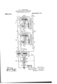
Further objects; features and advantages will more clearly appear from the detailed description given below taken in connection with the accompanying drawing which diagrammatically shows a train lighting system embodying one form of my invention.
In the drawing, A, B and 0 represent three train units, of which the unit A may be the locomotive or baggage car upon which the main generator 1 is situated. The units B and C represent cars or coaches carrying the lighting or work'ci-rcuits 2, 2. Each car 'is also provided with a storage battery 3, 3.
Extending throughout the various train unit-s is a feeding conductor 4' which connects the positive side of the generator 1 with the various circuits 2,'by means of connectors 5, 5. Also extending throughout the various train units is a conductor 6 which connects the positive side of the generator 1 with the various batteries by means of connectors 7. The conductor 6, therefore, acts as a charging conductor for the purpose of conveying the charging current to the batteries 3, 3. In order to increase the potential of the charging conductor 6 in order to provide the proper voltage for charging the various batteries I provide a booster 8 in series with the conductor 6, also extending throughout the various train units is a conductor 9 which connects with the negative terminal of the generator 1. Extending through the train units B and C is conductor 10 which is con circuits, the batteries and work circuits of each car being'connected to the conductor 10 by connectors 12.- The Various train conductors 4:, 6, 9 and 10 are connected together between the various train units by connectors 13.
The booster 8 is provided with a controlling field coil 14 energized by a counterelectromotive .force exciter 15 which is controlled in the usual manner'by a field coil tions are made by 16 connected in shunt to the resistance 17 The exciter 15 and booster 8 are driven by a motor 18 in the usual manner.
Each of the units B and C is provided with an electro-responsive switch 19 which in its lower position connects the battery 3 directly across the work circuit 2 by electrically connecting the terminals 20. When the switch 19 is in its uppermost position the connection between the terminals 20 is broken and said switch makes electrical connection between the contact terminals 21, 21, so that the battery .is connected directly to the charging conductor 6. These conneca blade 22 carried by the movable parts of the switch 19 and when the blade 22 is in its lowermost position the connection between the terminals 21 is broken so thatthe battery is disconnected from the charging circuit 6. -Each. switch 19 is also provided with a blade 23 which when in its uppermostposition electrically connects contact terminals 24 to connect the various work circuits directly wit-h the feed ing conductor 4. It will thus be seen .that when each of the switches 19 are in their lowermost position the battery 3 is connected directly and only to the work circuit 2 and is entirely disconnected from both the positive feeding and charging conductors 4 and 7. Vhen the switch is in its uppermost position the battery 3 is connected di rectly to the charging conductor while the work circuit 2 is connected directlyto the feeding conductor 4, so that the battery may be charged and the work circuit fed at independent voltages.
25 represents a'switch arranged to connect the terminals 27, 27 so as to complete a circuit 28 which includes a magnet coil 29 operating upon a switch 30 when the switch 25 is in its lowermost position. When the switch 25 is in its uppermost position it connects terminals 31, 31, which completes a circuit 32 in series with the magnet coil 33 which also operates upon the switch 30 but in the opposite direction from the magnetcoil 29. The switch 25 is maintained in its lowermost position by gravity and is arranged to be drawn upward by means of the magnet coil 34 connected across the conductors 4 and 9 so as to be responsive to the voltage of the main generator 1. Thus when the switch 25 is lowered the coil 29 is energized, being connected between the conductors ,9 and 6, and when the switch 25 is raised under the action of coil 34 the coil 33 is energized, being also connected across the conductors 9 and C. Upon the energization of coil 33 the switch 30 is raised, thus making electrical connection between the contact terminals 35 and 36 so as to connect that portion of the feeding conductor 4 upon .the unit A with that portion of the feeding conductor 4 on the various other train units. \Vhen the switch 25 is in its lowermost position the coil 33 is 29 is energized so that the switch 30 is pulled down, thus opening the circuit throu h the conductor 4so that it isno longer ed by the generator 1.
The switches 19 on the units B and O are arranged to be drawn upward in order to connect the batteries with the charging conductor 7 and the work circuits with the feeding conductor 4 by means of magnet coils 39, one terminal of which is connected to the negative conductors 12 by means of wires 40 and the other terminal of which is connected to a contact 41.
42, 42 represents switches arranged to con nect the terminal 41 with a contact terminal 43 when these switches are in their uppermost position, so that the magnet coil 39 will be connected between negative conductor 9 and the positive conductor 6 by means of Wires 45. When the switches 42 are in their lowermost position they connect contact terminals 46 to complete a circuit 47 through a magnet coil 48, so that the magnet coil 48 is connected between the positive conductor 6 and the negative conductor 10. The magnet coils 39 and 48 act in opposite directions upon the switches 19, the coils 39 operating to raise the switches and the coils 48 operating to drop the switches. The switches 42 are controlled by means of magnet coils 49 which are connected between the positive conductor 4 and the negative conductor 10 by a circuit 50.
51 and 52 are switches which are in series with the coils 39 and 48 respectively.
The system as represented shows the various parts in the position they Would keep when the main generator 1 is shut down or is practically inoperative. When the generator 1 is started up and produces a predetermined voltage the coil 34 acts upon the switch 25 to attract the same, thereby connecting contact terminals 31 and energizing the magnet coil 33 of switch 30. This causes the switch 30 to be attracted upwardly to connect the contact terminals 35 and 36' so that the circuit through the train conductor 4 is completed and extends through the various units B and C and be comes energized. Immediately there exists this diflerence of potential between the train conductors 4 and 10 the coils 49 become energized so that the switches 42 are attracted upwardly to connect the contact terminals 41 and 43, thus completing the circuit through the magnet coils 39 to energize the same. This causes the switches 19 to be drawn upwardly to connect the contact terminals 21, 21 together and the contact terminals 24, 24 together, so that the battery will become directly connected to the chargdenergized and the coil sition aslong as the generator furnishes the proper voltage to supply the system.
When the generator voltage decreases upon its being shut down the coil 34 of switch 25 is weakened, or if the batteries have a suiiicient voltage areverse current is sent through the coil 51' which is connect ed in series in the conductor 9. This energization of the coil 51' further decreases the attraction of the switch 25 so that it is effectively released and connection is made between the contact terminals 27, 27. This energizes magnet coil 29 of switch 30 so 'that it is attracted downwardly and the circuit through conductor ,4 opened so that the train conductor 4 upon the various units becomes opened. This .action denergizes the various voltage coils 49, '49, which operate the switches 42 so that these switches are dropped to their lowermost position, thereby opening the circuit 39, 39 and closing the circuit through the magnet coils 48, 48 of the main switches 19 so that the switches 19 are attracted to their lowermost positions in which the blades 22 thereof connect the terminals 20 so that the batteries 3 are connected to the work circuit 2 and are wholly and entirely disconnected from both the positive conductors, namely, the charging conductor 6 and the feeding conductor 4.
The small hand switches 60 which I have shown as bridging the contacts 24, 24, may be closed, so that if desirable, all the batteries may be charged in parallel in the yards when the unit on which the generator is placed is disconnected, in which case a separate source of electromotive force would be applied to the conductors 4 and 10. Also upon failure of the generator in service the batteries may be thus connected to jointly supply the load with the generator.
From the above it will be apparent that upon a certain decrease in voltage of the generator 1 or when the generator 1 is shut down the various switches are brought into action to disconnect the various batteries from all of the train conductors of one potential so that all of the various train conductors extending through the various units are rendered dead and deenergized. It will further be apparent that the various ob-' jects and advantages are accomplished in a simple and effective manner and constitute an important improvement in the way of safeguarding not only the electrical apparatus on the various train units but also in preventing injury to persons who may occasionally or-otherwise come into' contact with the various train conductors when the same are not in operation.
Although I have'described my improvements with relation to a specific system of electrical distribution and have shown and described them in great detail, yet I do not i desire to be limited to such details but veution what IIclaim as new and desire to secure by Letters Patent, is:
1. In a train lighting system, a generator feeding conductor for the various work circuits extending through the various train units, a charging, conductor for the batteries extending through the various train units, a common return conductor for the batteries and-work circuits, and means responsive to a decrease in the generator voltage for rendering said batteries disconnected from various of said conductors to render all-of said conductors dead. 2. In a train lighting system, a generato on one train unit, a plurality of batteries and work circuits on other train units, a feeding conductor for the various work circuits extending through the various train units, a charging conductor for the batteries extending through the various train batteries and work circuits, and means for disconnecting the batteries from all the conductors which are normally connected to one side of the genera-tor responsive to a decrease in the voltage of the generator.
3. In an electrical system of distribution, a source of electromotive force, a battery and work circuit arranged to be fed thereby, conductors for connecting the battery and work circuit with said source, a switch member in series with the work circuit for opening the conductor leading to the work circuit from the source, a switch member in series with the battery for'opening the conductor leading to the battery, and means for actuating said members responsive to variations in the electrical condition of the system.
4. In an electrical system of distribution, a source of electromotive force, a plurality of'batteries and work circuits arranged to be fed thereby, conductors for connecting the batteries and work circuits with said source, a switch member in series with each work circuit for opening the conductor leading to each work circuit from the source, a switch member in series with each battery for opening the conductor leading to each battery, and means for actuating said members responsive to variations in the electrical condition of the system.
5. In combination,-a plurality of work circuits, a plurality of batteries therefor, a common feeding conductor for the Work circuits, a. common chargingconductor for the batteries, a common return conductor, and a switch apparatus for automatically and wholly disconnecting each of the batteries Having fully and clearly explained my in-' on one train unit, a plurality of batteries and work circuits on other tram units, a
units, a common return conductor for the a plurality of units, a generator on one unit,
a storage battery and work circuit on each of the other units, a feeding conductor extending through the various units and connected to the various work circuits, a charging conductor extending through the various units andconnected to the various abatteries to charge the same, a common return conductor extending through the various train units-and connected to the various batteries and work circuits and means for independently disconnecting the batteries and work circuits on each unit from all of said conductors of one polarity responsive to a. decrease in generator voltage.
7 In an electrical system of distribution, a plurality of train units, a'generator on the train, a storage battery and work circuit on each of the units, a feeding train conductor extending from the generator through the various train units and feeding the various work circuits, a charging train conductor extending through the various train units and connected to the batteries for charging the same, a return train conductor for the batteries and Work circuits extending through the various train units, switches on each unit for disconnecting the battery and work circuit thereon from all of said conductors of one polarity and means for controlling said switches responsive to a decrease in the generator voltage.
8. In an electrical system of distribution, a plurality of train units, a generator on the train, a storage battery and work circuit on each of the units, a feeding train conductor extending from the generator through the various train units and feeding the various work circuits, a charging train conductor extending through the various train units and connected to the batteries for charging the same, a return train conductor for the batteries and work circuits extending through the various train units, and means for disconnectingthe battery and work circuit 011 each unit from said feeding and charging conductors responsive to a change in the electrical condition of the system.
9. In an electrical system of distribution, a plurality of train units, a generator on the 1 train, a storage battery and work circuit on each of the units, a feeding train conduct-or extending from the generator through the various train units and feedin the various work circuits, a charging train conductor extending through the various train units and connected to the batteries for charging the same, a return train conductor for the batteries and work circuits extending extending through the various train units and connected to the batteries for ohargin the same, a' return train conductor for the batteries and work circuits extending through the various train units, a switch on various units for disconnecting the batteries and work circuits thereon from said charging and feeding conductors and a solenoid on said units for controlling the action of said switches responsive to the electrical condition of the generator.
11. In an electrical system of distribution, a plurality'of train units, a storage battery and work circuit on each of the units, a generator, a feeding train conductor extending from the enerator through the various train units an feeding the various work circuits, a charging train conductor extending through the various train units and connected to the batteries for charging the same, a return train conductor for the batteries and work circuits extending through the various train units, a switch on each unit with the batteries and work circuits for wholly disconnecting the battery thereon from the charging and feeding conductors and a coil responsive to generator voltage for controllingthe action of said switches.
12. In an electrical system of distribution,
a plurality of train units, a storage battery and work circuit on each of the units, a generator, a feeding train conductor extending from the generator through the various train units and feeding the various work circuits, a charging train conductor extending through the various train units and connected to the batteries for charging the same, a return train conductor for the batteries and work circuits extending through the various train units, a switch for opening one of said conductors between the generator and one of the work circuits and batteries, switches on various units for wholly discon- 1 necting the batteries thereon from said feeding and charging conductors and a coil responsive to the action of said first mentioned switch for controlling the action of said last mentioned switches responsive thereto.
13. In an electrical system of distribution, a plurality of train units, a storage battery and Work circuit on each of the units, a generator, a feeding train conductor extending from the generator through the various 13 -between' the feeding conductor and the return conductor, and switches on various of the train unitsfor disconnecting the batteries and work circuits from said feeding and char 'ng conductors, said switches being controlle by-said coils.
v 14.. In a system of electrical distribution, a generator, a plurality of train units each carryin a work circuit'and a storage battery, a eeding conductor extending throu h the various train units for connecting the work circuits with the generator, a charging conductor extending through the various train units for charging the batteries, a booster in said circuit a common return conductor extending through the various train units to the generator, a switch for opening the feeding circuit to disconnect the generator from the work circuits, a switch for controlling the action of said last mentioned switch responsive to the generator voltage and the generator current and means for renderin the various conductors on the train units dead responsive to the opening of said first mentioned switch.
15. Ina system of electrical distribution, a generator, :1 lurality of train units each carryin a wor circult and a storage battery, a eeding conductor extending through the various train units for connecting the I work circuits with the generator, a charging conductor extending through the various train units for charging the batteries, a
, booster'in said circuit, a common return conductor extending through the various'train units to the generator, a switch for opening the feeding circuit to disconnect the meretor from the work circuits, a switch fbr controlling the action of said last mentioned switch responsive to the generator voltage and the generator current and means for rendering the various conductors on the train units dead responsive to the opening of said first mentioned switch, said means including switches on each car for disconnecting the battery and work circuit thereon from the feeding and charging conductors.
16. In an electrical system of distribution, a plurality of train units, a generator, a storage battery and work circuit on each of the units, a feeding train conductor extending from the generator through the various train units and feeding the various work circuits, a charging train conductor extending through the various train units and 'connected to the batteries for charging the same a return train conductor for the batteries and work circuits extending through the various train units, and means for rendering said conductors dead responsive to a shutdown of the generator. J
17. In combination, a work circuit, a battery, a feeding conductor for the work circuit, a charging conductor for the battery, a common return conductor and a switch apparatus for automatically and wholly disconnecting the battery and workcircuit from said charging and feeding conductors responsive to a drop in voltage across the feeding and return conductors, said switch apparatus being provided with two coils, each operating upon it to cause it to move in the opposite "direction from other coil causes it to move;
18. In an electrical system of distribution, a plurality of train units, a battery and work circuit on each unit, a source ofelectrical energy, a plurality of conductors leading from said source through said units for feeding the batteries and work circuits, means for disconnecting the source from said conductors responsive to condition of the system and means for disconnectin each battery from all of said conductors 0 one polarity to render all of said conductors dead, responsive to a change in the electrical condition of the system.
that in which the a change in the electrical In testimony "whereof, I have signed my A. TURBA YNE.
Witnesses:
THOS. Donnms,
W. H. IE'A'I'IENPEN.
Priority Applications (1)
| Application Number | Priority Date | Filing Date | Title |
|---|---|---|---|
| US1909479755 US991111A (en) | 1909-02-24 | 1909-02-24 | Electrical system of distribution. |
Applications Claiming Priority (1)
| Application Number | Priority Date | Filing Date | Title |
|---|---|---|---|
| US1909479755 US991111A (en) | 1909-02-24 | 1909-02-24 | Electrical system of distribution. |
Publications (1)
| Publication Number | Publication Date |
|---|---|
| US991111A true US991111A (en) | 1911-05-02 |
Family
ID=3059447
Family Applications (1)
| Application Number | Title | Priority Date | Filing Date |
|---|---|---|---|
| US1909479755 Expired - Lifetime US991111A (en) | 1909-02-24 | 1909-02-24 | Electrical system of distribution. |
Country Status (1)
| Country | Link |
|---|---|
| US (1) | US991111A (en) |
-
1909
- 1909-02-24 US US1909479755 patent/US991111A/en not_active Expired - Lifetime
Similar Documents
| Publication | Publication Date | Title |
|---|---|---|
| US1908985A (en) | Electric train lighting system | |
| US963339A (en) | Electrical system of distribution. | |
| US1010466A (en) | System of electrical distribution. | |
| US521436A (en) | System of electrical distribution | |
| US484208A (en) | Harry ward leonard | |
| US1231662A (en) | Control system. | |
| US799528A (en) | Train-lighting system. | |
| US531962A (en) | parker | |
| US1236180A (en) | Lighting system. | |
| US556079A (en) | Electric car-lighting system | |
| US799521A (en) | Train-lighting system. | |
| US1481919A (en) | Electric power system | |
| US1958665A (en) | Electrical apparatus | |
| US771710A (en) | System of electrical distribution. | |
| US467358A (en) | Regulator for electric generators | |
| US1418398A (en) | Rectifier system | |
| US637119A (en) | Electric railway. | |
| US1023121A (en) | Electric-lighting system. | |
| US782550A (en) | Electric system. | |
| US735171A (en) | System of electrical distribution. | |
| US264661A (en) | Regulator for dynamo-electric machines | |
| US669941A (en) | Electric switch. | |
| US991105A (en) | Electrical system of distribution. | |
| US447215A (en) | Electric-railway system | |
| US976151A (en) | Electrical system of distribution. |