US9909388B2 - Pressure indexing sliding side door with rapid actuation - Google Patents
Pressure indexing sliding side door with rapid actuation Download PDFInfo
- Publication number
- US9909388B2 US9909388B2 US14/420,406 US201214420406A US9909388B2 US 9909388 B2 US9909388 B2 US 9909388B2 US 201214420406 A US201214420406 A US 201214420406A US 9909388 B2 US9909388 B2 US 9909388B2
- Authority
- US
- United States
- Prior art keywords
- valve
- closure device
- exterior
- interior
- pressure differentials
- Prior art date
- Legal status (The legal status is an assumption and is not a legal conclusion. Google has not performed a legal analysis and makes no representation as to the accuracy of the status listed.)
- Active, expires
Links
Images


Classifications
-
- E—FIXED CONSTRUCTIONS
- E21—EARTH OR ROCK DRILLING; MINING
- E21B—EARTH OR ROCK DRILLING; OBTAINING OIL, GAS, WATER, SOLUBLE OR MELTABLE MATERIALS OR A SLURRY OF MINERALS FROM WELLS
- E21B34/00—Valve arrangements for boreholes or wells
- E21B34/06—Valve arrangements for boreholes or wells in wells
- E21B34/10—Valve arrangements for boreholes or wells in wells operated by control fluid supplied from outside the borehole
-
- E21B2034/007—
-
- E—FIXED CONSTRUCTIONS
- E21—EARTH OR ROCK DRILLING; MINING
- E21B—EARTH OR ROCK DRILLING; OBTAINING OIL, GAS, WATER, SOLUBLE OR MELTABLE MATERIALS OR A SLURRY OF MINERALS FROM WELLS
- E21B2200/00—Special features related to earth drilling for obtaining oil, gas or water
- E21B2200/06—Sleeve valves
Definitions
- This disclosure relates generally to equipment utilized and operations performed in conjunction with a subterranean well and, in one example described below, more particularly provides a pressure indexing sliding side door with rapid actuation.
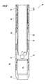
- FIG. 1 is a representative partially cross-sectional view of a well system and associated method which can embody principles of this disclosure.
- FIG. 2 is a representative cross-sectional view of a valve which can embody the principles of this disclosure.
- FIG. 3 is a representative cross-sectional view of an incremental displacement device of the valve.
- FIG. 4 is a representative cross-sectional view of an accelerator device of the valve.
- FIG. 5 is a representative cross-sectional view of the accelerator device after actuation of the valve.
- FIG. 6 is a representative cross-sectional view of the valve after actuation.
- FIG. 1 Representatively illustrated in FIG. 1 is a system 10 for use with a subterranean well, and an associated method, which system and method can embody principles of this disclosure.
- system 10 and method are merely one example of an application of the principles of this disclosure in practice, and a wide variety of other examples are possible. Therefore, the scope of this disclosure is not limited at all to the details of the system 10 and method described herein and/or depicted in the drawings.
- a tubular string 12 is positioned in a wellbore 14 lined with casing 16 and cement 18 .
- the wellbore 14 could be uncased or open hole.
- a valve 20 is connected in the tubular string 12 , so that a longitudinal flow passage 22 extending through the tubular string also extends through the valve.
- the valve 20 includes openings 24 and a closure device 26 which selectively blocks flow through the openings, so that fluid communication is selectively permitting and prevented between the flow passage 22 in an interior of the valve, and an annulus 28 on an exterior of the valve.
- the closure device 26 in the FIG. 1 example comprises an axially displaceable sleeve, and the openings 24 are formed in a generally tubular housing 30 , and so the valve 20 is of the type known to those skilled in the art as a sliding sleeve valve or sliding side door.
- valves e.g., ball valves, plug valves, etc.
- other types of valves can benefit from the principles described herein.
- the valve 20 in the FIG. 1 example includes an actuator 32 which incrementally displaces the closure device 26 in response to pressure differentials applied between the flow passage 22 and the annulus 28 .
- the actuator 32 accelerates the closure device 26 to a desired open or closed position. In this manner, the closure device 26 does not have to be incrementally displaced all the way to the desired position (which could take a large number of incremental displacements).
- FIG. 2 a cross-sectional view of an example of the valve 20 is representatively illustrated.
- the actuator 32 of the valve 20 includes an incremental displacement device 34 and an accelerator device 36 .
- the valve 20 is provided with tubular string connections 38 for connecting the valve in the tubular string 12 .
- tubular string connections 38 for connecting the valve in the tubular string 12 .
- the valve 20 could be connected in other tubular strings and could be used in other systems and methods, in keeping with the scope of this disclosure.
- the incremental displacement device 26 incrementally axially displaces the closure device 26 toward an open position in which fluid communication is permitted between the interior and the exterior of the valve 20 . In the open position, the closure device 26 does not block flow through the openings 24 , so that the flow passage 22 is in communication with the annulus 28 .
- the accelerator device 36 accelerates the displacement of the closure device 26 axially to the open position when a predetermined pattern of pressure differentials have been applied between the flow passage 22 and the annulus 28 .
- the incremental displacement device does not displace the closure device 26 all the way to its open position.
- the increment displacement device 34 includes an annular piston 40 which is downwardly biased by a pressure differential from an interior of the valve 20 to an exterior of the valve.
- the piston 40 is biased upwardly by a biasing device 42 , such as, a coiled compression spring.
- a biasing device 42 such as, a coiled compression spring.
- other types of biasing devices for example, compressed gas chambers, liquid springs, extension springs, etc. may be used in other examples.
- a gripping device 44 displaces with the piston 40 and grips an outer serrated or toothed tubular surface 46 of the closure device 26 .
- the gripping device 44 allows upward displacement of the closure device 26 toward its open position, but the gripping engagement between the gripping device and the surface 46 prevents downward displacement of the closure device relative to the piston 40 .
- the gripping device 44 is depicted in FIG. 3 as being a generally tubular sleeve which is internally circumferentially toothed, and is biased by its own elasticity into gripping contact with the surface 46 .
- gripping devices for example, gripping wedges, spring-biased teeth, etc.
- other types of gripping devices may be used in other examples.
- Shear members 48 releasably retain the piston 40 against displacement relative to the closure device 26 .
- the shear members 48 will shear and allow the piston 40 to displace downwardly against a biasing force exerted upwardly by the biasing device 42 .
- the biasing device 42 When the pressure differential from the passage 22 to the annulus 28 is sufficiently reduced, the biasing device 42 will displace the piston 40 upwardly, and the closure device 26 will be displaced upwardly with the piston (the gripping device 44 preventing the piston from displacing upwardly without the closure device). The piston 40 can then be displaced downwardly by increasing the pressure differential from the passage 22 to the annulus 28 .
- the gripping device 44 allows such downward displacement of the piston 40 relative to the closure device 26 .
- Another gripping device 62 prevents the closure device 26 from displacing downwardly with the piston 40 , but permits upward displacement of the closure device with the piston.
- the closure device 26 is incrementally displaced axially upward in response to repeated applications of increased and decreased pressure differentials from the passage 22 to the annulus 28 .
- the incremental displacement device 34 it is not desired in this example for the incremental displacement device 34 to be used to displace the closure device 26 all the way to its open position. Instead, it is desired that the incremental displacement device 34 displace the closure device 26 to a position in which the accelerator device 36 will more rapidly displace the closure device to its open position.
- the accelerator 36 includes a biasing device 50 and a sleeve 52 having radially flexible collet fingers 54 formed in an upper end thereof.
- the biasing device 50 biases the sleeve 52 upward, but the sleeve is prevented from displacing upward by engagement between the collet fingers 54 and a shoulder 56 in the housing 30 .
- the collet fingers 54 are initially supported radially outward into engagement with the shoulder 56 by an outer surface 58 on the closure device 26 .
- valve 20 is representatively illustrated with the closure device 26 displaced upwardly to its open position. Note that the collet fingers 54 are engaged with the recess 60 , so that the biasing device 50 biases the closure device 26 upward with the sleeve 52 .
- closure device 26 is depicted in its open position.
- the closure device 26 no longer blocks flow through the openings 24 , and fluid communication is now permitted between the interior passage 22 and the exterior annulus 28 .
- valve 20 described above can be opened by applying a predetermined level of a pressure differential from the passage 22 to the annulus 28 to shear the shear members 48 , and then the valve can be opened by applying a predetermined pattern of pressure differentials.
- valve 20 can include a closure device 26 which selectively permits and prevents fluid communication between an interior and an exterior of the valve 20 , an incremental displacement device 34 which incrementally displaces the closure device 26 in response to pressure differentials between the interior and the exterior of the valve 20 , and an accelerator device 36 which accelerates displacement of the closure device 26 in response to a predetermined pattern of the pressure differentials.
- the valve 20 may include tubular string connectors 38 at opposite ends thereof, whereby the valve 20 is configured for controlling flow between an interior and an exterior of a tubular string 12 .
- the incremental displacement device 34 may axially displace the closure device 26 .
- the accelerator device 36 may axially displace the closure device 26 .
- the closure device 26 could be rotationally displaced, helically displaced, etc.
- the accelerator device 36 can comprise at least one biasing device 50 which applies a force to the closure device 26 in response to the predetermined pattern of pressure differentials.
- the accelerator device 36 may displace the closure device 26 to an open or closed position.
- the incremental displacement device 34 may comprise a gripping sleeve (such as gripping devices 44 , 62 ) which permits incremental axial displacement of the closure device 26 in a first direction, but which prevents axial displacement of the closure device 26 in an opposite second direction, in response to the pressure differentials.
- a gripping sleeve such as gripping devices 44 , 62
- the incremental displacement device 34 may displace the closure device toward an open position in which fluid communication is permitted between an interior and an exterior of the valve 20 .
- the accelerator device 36 may displace the closure device 26 to an open position in which fluid communication is permitted between the interior and the exterior of the valve 20 .
- a method of operating a valve 20 in a well is also provided to the art by the above disclosure.
- the method can comprise: applying a predetermined pattern of pressure differentials between an interior and an exterior of a tubular string 12 in which the valve 20 is connected, thereby displacing a closure device 26 of the valve 20 ; and accelerating displacement of the closure device 26 in response to the predetermined pattern of pressure differentials, thereby displacing the closure device 26 to a selected one of an open and a closed position.
Landscapes
- Life Sciences & Earth Sciences (AREA)
- Engineering & Computer Science (AREA)
- Geology (AREA)
- Mining & Mineral Resources (AREA)
- Physics & Mathematics (AREA)
- Environmental & Geological Engineering (AREA)
- Fluid Mechanics (AREA)
- General Life Sciences & Earth Sciences (AREA)
- Geochemistry & Mineralogy (AREA)
- Mechanically-Actuated Valves (AREA)
- Lift Valve (AREA)
Abstract
Description
Claims (18)
Applications Claiming Priority (1)
| Application Number | Priority Date | Filing Date | Title |
|---|---|---|---|
| PCT/US2012/071860 WO2014105026A1 (en) | 2012-12-27 | 2012-12-27 | Pressure indexing sliding side door with rapid actuation |
Publications (2)
| Publication Number | Publication Date |
|---|---|
| US20150218908A1 US20150218908A1 (en) | 2015-08-06 |
| US9909388B2 true US9909388B2 (en) | 2018-03-06 |
Family
ID=51021856
Family Applications (1)
| Application Number | Title | Priority Date | Filing Date |
|---|---|---|---|
| US14/420,406 Active 2033-11-03 US9909388B2 (en) | 2012-12-27 | 2012-12-27 | Pressure indexing sliding side door with rapid actuation |
Country Status (2)
| Country | Link |
|---|---|
| US (1) | US9909388B2 (en) |
| WO (1) | WO2014105026A1 (en) |
Families Citing this family (3)
| Publication number | Priority date | Publication date | Assignee | Title |
|---|---|---|---|---|
| GB201415275D0 (en) * | 2014-08-28 | 2014-10-15 | Tco In Well Technologies Uk Ltd | Soft Open Device |
| WO2017065747A1 (en) * | 2015-10-13 | 2017-04-20 | Halliburton Energy Services, Inc. | Fire-on-demand remote fluid valve |
| US11286749B2 (en) * | 2018-05-22 | 2022-03-29 | Halliburton Energy Services, Inc. | Remote-open device for well operation |
Citations (24)
| Publication number | Priority date | Publication date | Assignee | Title |
|---|---|---|---|---|
| US3889751A (en) | 1974-02-01 | 1975-06-17 | Exxon Production Research Co | Subsurface safety valve |
| US4058165A (en) | 1974-10-10 | 1977-11-15 | Halliburton Company | Wellbore circulating valve |
| US4448254A (en) | 1982-03-04 | 1984-05-15 | Halliburton Company | Tester valve with silicone liquid spring |
| US4474242A (en) * | 1981-06-29 | 1984-10-02 | Schlumberger Technology Corporation | Annulus pressure controlled reversing valve |
| US4566478A (en) * | 1982-04-27 | 1986-01-28 | Otis Engineering Corporation | Well safety and kill valve |
| US5343949A (en) | 1992-09-10 | 1994-09-06 | Halliburton Company | Isolation washpipe for earth well completions and method for use in gravel packing a well |
| US5597042A (en) | 1995-02-09 | 1997-01-28 | Baker Hughes Incorporated | Method for controlling production wells having permanent downhole formation evaluation sensors |
| US5609178A (en) | 1995-09-28 | 1997-03-11 | Baker Hughes Incorporated | Pressure-actuated valve and method |
| WO1997047850A1 (en) | 1996-06-11 | 1997-12-18 | The Red Baron (Oil Tools Rental) Limited | Multi-cycle circulating sub |
| US5826661A (en) | 1994-05-02 | 1998-10-27 | Halliburton Energy Services, Inc. | Linear indexing apparatus and methods of using same |
| US6276458B1 (en) | 1999-02-01 | 2001-08-21 | Schlumberger Technology Corporation | Apparatus and method for controlling fluid flow |
| US6397949B1 (en) | 1998-08-21 | 2002-06-04 | Osca, Inc. | Method and apparatus for production using a pressure actuated circulating valve |
| US6659186B2 (en) | 2000-05-12 | 2003-12-09 | Schlumberger Technology Corporation | Valve assembly |
| US6668936B2 (en) | 2000-09-07 | 2003-12-30 | Halliburton Energy Services, Inc. | Hydraulic control system for downhole tools |
| WO2004033849A1 (en) | 2002-10-11 | 2004-04-22 | Baker Hughes Incorporated | Hydraulic stepping valve actuated sliding sleeve |
| US6820697B1 (en) | 1999-07-15 | 2004-11-23 | Andrew Philip Churchill | Downhole bypass valve |
| US20080001111A1 (en) | 2006-07-03 | 2008-01-03 | Ross Richard J | Step ratchet mechanism |
| WO2009009281A2 (en) | 2007-07-10 | 2009-01-15 | Baker Hughes Incorporated | Incremental annular choke |
| US7594542B2 (en) * | 2006-04-28 | 2009-09-29 | Schlumberger Technology Corporation | Alternate path indexing device |
| US20100051289A1 (en) | 2008-08-26 | 2010-03-04 | Baker Hughes Incorporated | System for Selective Incremental Closing of a Hydraulic Downhole Choking Valve |
| US7870908B2 (en) | 2007-08-21 | 2011-01-18 | Schlumberger Technology Corporation | Downhole valve having incrementally adjustable open positions and a quick close feature |
| US8061431B2 (en) | 2009-02-18 | 2011-11-22 | Halliburton Energy Services, Inc. | Method of operating a pressure cycle operated perforating firing head and generating electricity in a subterranean well |
| US8186439B2 (en) * | 2007-12-19 | 2012-05-29 | Baker Hughes Incorporated | Controller for a hydraulically operated downhole tool |
| US20160123113A1 (en) * | 2014-10-31 | 2016-05-05 | Baker Hughes Incorporated | Flow-Activated Flow Control Device and Method of Using Same in Wellbore Completion Assemblies |
-
2012
- 2012-12-27 WO PCT/US2012/071860 patent/WO2014105026A1/en not_active Ceased
- 2012-12-27 US US14/420,406 patent/US9909388B2/en active Active
Patent Citations (24)
| Publication number | Priority date | Publication date | Assignee | Title |
|---|---|---|---|---|
| US3889751A (en) | 1974-02-01 | 1975-06-17 | Exxon Production Research Co | Subsurface safety valve |
| US4058165A (en) | 1974-10-10 | 1977-11-15 | Halliburton Company | Wellbore circulating valve |
| US4474242A (en) * | 1981-06-29 | 1984-10-02 | Schlumberger Technology Corporation | Annulus pressure controlled reversing valve |
| US4448254A (en) | 1982-03-04 | 1984-05-15 | Halliburton Company | Tester valve with silicone liquid spring |
| US4566478A (en) * | 1982-04-27 | 1986-01-28 | Otis Engineering Corporation | Well safety and kill valve |
| US5343949A (en) | 1992-09-10 | 1994-09-06 | Halliburton Company | Isolation washpipe for earth well completions and method for use in gravel packing a well |
| US5826661A (en) | 1994-05-02 | 1998-10-27 | Halliburton Energy Services, Inc. | Linear indexing apparatus and methods of using same |
| US5597042A (en) | 1995-02-09 | 1997-01-28 | Baker Hughes Incorporated | Method for controlling production wells having permanent downhole formation evaluation sensors |
| US5609178A (en) | 1995-09-28 | 1997-03-11 | Baker Hughes Incorporated | Pressure-actuated valve and method |
| WO1997047850A1 (en) | 1996-06-11 | 1997-12-18 | The Red Baron (Oil Tools Rental) Limited | Multi-cycle circulating sub |
| US6397949B1 (en) | 1998-08-21 | 2002-06-04 | Osca, Inc. | Method and apparatus for production using a pressure actuated circulating valve |
| US6276458B1 (en) | 1999-02-01 | 2001-08-21 | Schlumberger Technology Corporation | Apparatus and method for controlling fluid flow |
| US6820697B1 (en) | 1999-07-15 | 2004-11-23 | Andrew Philip Churchill | Downhole bypass valve |
| US6659186B2 (en) | 2000-05-12 | 2003-12-09 | Schlumberger Technology Corporation | Valve assembly |
| US6668936B2 (en) | 2000-09-07 | 2003-12-30 | Halliburton Energy Services, Inc. | Hydraulic control system for downhole tools |
| WO2004033849A1 (en) | 2002-10-11 | 2004-04-22 | Baker Hughes Incorporated | Hydraulic stepping valve actuated sliding sleeve |
| US7594542B2 (en) * | 2006-04-28 | 2009-09-29 | Schlumberger Technology Corporation | Alternate path indexing device |
| US20080001111A1 (en) | 2006-07-03 | 2008-01-03 | Ross Richard J | Step ratchet mechanism |
| WO2009009281A2 (en) | 2007-07-10 | 2009-01-15 | Baker Hughes Incorporated | Incremental annular choke |
| US7870908B2 (en) | 2007-08-21 | 2011-01-18 | Schlumberger Technology Corporation | Downhole valve having incrementally adjustable open positions and a quick close feature |
| US8186439B2 (en) * | 2007-12-19 | 2012-05-29 | Baker Hughes Incorporated | Controller for a hydraulically operated downhole tool |
| US20100051289A1 (en) | 2008-08-26 | 2010-03-04 | Baker Hughes Incorporated | System for Selective Incremental Closing of a Hydraulic Downhole Choking Valve |
| US8061431B2 (en) | 2009-02-18 | 2011-11-22 | Halliburton Energy Services, Inc. | Method of operating a pressure cycle operated perforating firing head and generating electricity in a subterranean well |
| US20160123113A1 (en) * | 2014-10-31 | 2016-05-05 | Baker Hughes Incorporated | Flow-Activated Flow Control Device and Method of Using Same in Wellbore Completion Assemblies |
Non-Patent Citations (4)
| Title |
|---|
| Halliburton; "FS Fluid Loss Isolation Barrier Valve", H07007, dated Nov. 2013, 2 pages. |
| Halliburton; "Isolation Barrier Valves", H07542, dated Jun. 2010, 4 pages. |
| Halliburton; "LA0 Liquid Spring-Actuated Anvil Plugging System", Packers Article 6-68-6-69, received Mar. 13, 2015, 2 pages. |
| International Search Report with Written Opinion issued Sep. 2, 2013 for PCT Patent Application No. PCT/US12/071860, 15 pages. |
Also Published As
| Publication number | Publication date |
|---|---|
| WO2014105026A1 (en) | 2014-07-03 |
| US20150218908A1 (en) | 2015-08-06 |
Similar Documents
| Publication | Publication Date | Title |
|---|---|---|
| AU2008310966B2 (en) | Circulation control valve and associated method | |
| EP3757347B1 (en) | Circulation control valve and associated method | |
| US8596365B2 (en) | Resettable pressure cycle-operated production valve and method | |
| EP3673147B1 (en) | Shifting tool and associated methods for operating downhole valves | |
| US9885222B2 (en) | Stage tool apparatus and components for same | |
| US10648274B2 (en) | Apparatus and method for opening and closing in multiple cycles a downhole sleeve using an intervention tool | |
| US20170241237A1 (en) | Remotely operated production valve and method | |
| US9909388B2 (en) | Pressure indexing sliding side door with rapid actuation | |
| US9920592B2 (en) | Well tool with indexing device | |
| CA2963386C (en) | Well tool with indexing device | |
| US9388666B2 (en) | Locking mechanism for downhole positioning of sleeves | |
| US9719324B2 (en) | Operation of multiple interconnected hydraulic actuators in a subterranean well | |
| EP4006300A1 (en) | Multiple setting and unsetting of inflatable well packer | |
| US20180266212A1 (en) | Re-closable Coil Activated Frack Sleeve | |
| CA2860778C (en) | Operation of multiple interconnected hydraulic actuators in a subterranean well |
Legal Events
| Date | Code | Title | Description |
|---|---|---|---|
| AS | Assignment |
Owner name: HALLIBURTON ENERGY SERVICES, INC., TEXAS Free format text: ASSIGNMENT OF ASSIGNORS INTEREST;ASSIGNOR:WEBBER, ANDREW J.;REEL/FRAME:029704/0311 Effective date: 20130102 |
|
| AS | Assignment |
Owner name: HALLIBURTON ENERGY SERVICES, INC., TEXAS Free format text: ASSIGNMENT OF ASSIGNORS INTEREST;ASSIGNOR:WEBBER, ANDREW J.;REEL/FRAME:034916/0189 Effective date: 20130102 |
|
| STCF | Information on status: patent grant |
Free format text: PATENTED CASE |
|
| MAFP | Maintenance fee payment |
Free format text: PAYMENT OF MAINTENANCE FEE, 4TH YEAR, LARGE ENTITY (ORIGINAL EVENT CODE: M1551); ENTITY STATUS OF PATENT OWNER: LARGE ENTITY Year of fee payment: 4 |
|
| MAFP | Maintenance fee payment |
Free format text: PAYMENT OF MAINTENANCE FEE, 8TH YEAR, LARGE ENTITY (ORIGINAL EVENT CODE: M1552); ENTITY STATUS OF PATENT OWNER: LARGE ENTITY Year of fee payment: 8 |