US9904474B2 - Control device and storage system - Google Patents

Control device and storage system Download PDF

Info

Publication number
US9904474B2
US9904474B2 US14/822,171 US201514822171A US9904474B2 US 9904474 B2 US9904474 B2 US 9904474B2 US 201514822171 A US201514822171 A US 201514822171A US 9904474 B2 US9904474 B2 US 9904474B2
Authority
US
United States
Prior art keywords
threshold value
data unit
storage device
access frequency
cache hit
Prior art date
Legal status (The legal status is an assumption and is not a legal conclusion. Google has not performed a legal analysis and makes no representation as to the accuracy of the status listed.)
Active, expires
Application number
US14/822,171
Other versions
US20160085446A1 (en
Inventor
Takuro Kumabe
Akihito Kobayashi
Motohiro Sakai
Shinichiro Matsumura
Takahiro Ohyama
Current Assignee (The listed assignees may be inaccurate. Google has not performed a legal analysis and makes no representation or warranty as to the accuracy of the list.)
Fujitsu Ltd
Original Assignee
Fujitsu Ltd
Priority date (The priority date is an assumption and is not a legal conclusion. Google has not performed a legal analysis and makes no representation as to the accuracy of the date listed.)
Filing date
Publication date
Application filed by Fujitsu Ltd filed Critical Fujitsu Ltd
Assigned to FUJITSU LIMITED reassignment FUJITSU LIMITED ASSIGNMENT OF ASSIGNORS INTEREST (SEE DOCUMENT FOR DETAILS). Assignors: SAKAI, MOTOHIRO, KOBAYASHI, AKIHITO, KUMABE, TAKURO, MATSUMURA, SHINICHIRO, OHYAMA, TAKAHIRO
Publication of US20160085446A1 publication Critical patent/US20160085446A1/en
Application granted granted Critical
Publication of US9904474B2 publication Critical patent/US9904474B2/en
Active legal-status Critical Current
Adjusted expiration legal-status Critical

Links

Images

Classifications

    • GPHYSICS
    • G06COMPUTING OR CALCULATING; COUNTING
    • G06FELECTRIC DIGITAL DATA PROCESSING
    • G06F3/00Input arrangements for transferring data to be processed into a form capable of being handled by the computer; Output arrangements for transferring data from processing unit to output unit, e.g. interface arrangements
    • G06F3/06Digital input from, or digital output to, record carriers, e.g. RAID, emulated record carriers or networked record carriers
    • G06F3/0601Interfaces specially adapted for storage systems
    • G06F3/0602Interfaces specially adapted for storage systems specifically adapted to achieve a particular effect
    • G06F3/061Improving I/O performance
    • GPHYSICS
    • G06COMPUTING OR CALCULATING; COUNTING
    • G06FELECTRIC DIGITAL DATA PROCESSING
    • G06F12/00Accessing, addressing or allocating within memory systems or architectures
    • G06F12/02Addressing or allocation; Relocation
    • G06F12/08Addressing or allocation; Relocation in hierarchically structured memory systems, e.g. virtual memory systems
    • G06F12/0802Addressing of a memory level in which the access to the desired data or data block requires associative addressing means, e.g. caches
    • G06F12/0806Multiuser, multiprocessor or multiprocessing cache systems
    • G06F12/0811Multiuser, multiprocessor or multiprocessing cache systems with multilevel cache hierarchies
    • GPHYSICS
    • G06COMPUTING OR CALCULATING; COUNTING
    • G06FELECTRIC DIGITAL DATA PROCESSING
    • G06F12/00Accessing, addressing or allocating within memory systems or architectures
    • G06F12/02Addressing or allocation; Relocation
    • G06F12/08Addressing or allocation; Relocation in hierarchically structured memory systems, e.g. virtual memory systems
    • G06F12/12Replacement control
    • GPHYSICS
    • G06COMPUTING OR CALCULATING; COUNTING
    • G06FELECTRIC DIGITAL DATA PROCESSING
    • G06F3/00Input arrangements for transferring data to be processed into a form capable of being handled by the computer; Output arrangements for transferring data from processing unit to output unit, e.g. interface arrangements
    • G06F3/06Digital input from, or digital output to, record carriers, e.g. RAID, emulated record carriers or networked record carriers
    • G06F3/0601Interfaces specially adapted for storage systems
    • G06F3/0628Interfaces specially adapted for storage systems making use of a particular technique
    • G06F3/0646Horizontal data movement in storage systems, i.e. moving data in between storage devices or systems
    • G06F3/0647Migration mechanisms
    • G06F3/0649Lifecycle management
    • GPHYSICS
    • G06COMPUTING OR CALCULATING; COUNTING
    • G06FELECTRIC DIGITAL DATA PROCESSING
    • G06F3/00Input arrangements for transferring data to be processed into a form capable of being handled by the computer; Output arrangements for transferring data from processing unit to output unit, e.g. interface arrangements
    • G06F3/06Digital input from, or digital output to, record carriers, e.g. RAID, emulated record carriers or networked record carriers
    • G06F3/0601Interfaces specially adapted for storage systems
    • G06F3/0668Interfaces specially adapted for storage systems adopting a particular infrastructure
    • G06F3/0671In-line storage system
    • G06F3/0683Plurality of storage devices
    • G06F3/0685Hybrid storage combining heterogeneous device types, e.g. hierarchical storage, hybrid arrays

Definitions

  • the embodiments discussed herein are related to a control device and a storage system.
  • the AST is a technology that automatically transfers and relocates data between storage tiers in accordance with a predetermined policy.
  • the storage tiers are constructed by a solid state drive (SSD) that has a short response time but with a high cost per unit capacity and a hard disk drive (HDD) that has a long response time but with a low cost per unit capacity.
  • SSD solid state drive
  • HDD hard disk drive
  • a more frequently accessed data unit is transferred to the SSD to be relocated, while a less frequently accessed data unit is transferred to the HDD to be relocated. Accordingly, a high performance (speed up of response) may be achieved in the storage system while maintaining a large capacity.
  • a storage system illustrated in FIG. 9 includes two host computers (hereinafter, simply referred to as hosts) # 0 and # 1 , a parent pool FTRP (flexible tier pool) including a plurality of storage devices (SSDs, HDDs, or the like), and a control device.
  • hosts hereinafter, simply referred to as hosts
  • FTRP flexible tier pool
  • SSDs storage devices
  • HDDs HDDs
  • the control device is provided between the hosts # 0 and # 1 and the parent pool FTRP, and includes two control units CMs (Controller Modules) # 0 and # 1 , each of which performs an input/output control for the parent pool FTRP in response to input/output requests from the hosts # 0 and # 1 .
  • CMs Controller Modules
  • Each of the CMs # 0 and # 1 is provided with a cache memory which temporarily holds a data unit stored in the parent pool FTRP.
  • the CMs # 0 and # 1 are communicably connected with each other.
  • a plurality of child pools FTSPs (flexible tier sub pools) implemented with different levels of RAIDs (redundant arrays of inexpensive disks), or a plurality of child pools FTSPs implemented with RAIDs constructed of different types of disks are prepared using the plurality of storage devices to form storage tiers.
  • the child pool FTSP # 0 is under the control of the CM # 0
  • the child pools FTSP # 1 and FTSP # 2 are under the control of the CM # 1
  • the child pool FTSP # 0 has the highest performance (shortest response time)
  • the child pool FTSP # 1 has the second highest performance (second shortest response time)
  • the child pool FTSP # 2 has the lowest performance (longest response time).
  • the child pool FTSP # 0 is an SSD
  • the child pool FTSP # 1 is a RAID1 or an online HDD
  • the child pool FTSP # 2 is a RAID5 or a near line HDD.
  • a volume (logical volume) of the AST is associated with the parent pool FTRP.
  • a finely divided unit TPPE thin provisioning pool element
  • TPPE thin provisioning pool element
  • the unit is called a chunk, and a plurality of chunks collected into a single group is called an FTRPE, a chunk collection, a chunk group, a data block, a transfer unit, or a data unit.
  • the performance information is collected for each data unit.
  • the performance information is, for example, an access frequency (number of accesses per unit time) of the data unit. It is determined, based on the collected access frequency, whether each data unit is to be transferred to a child pool residing in a higher tier, to a child pool residing in a lower tier, or is not to be transferred to another child pool.
  • Each data unit is transferred and relocated depending on the determination result. For example, as illustrated in FIG.
  • a cache control device that controls a cache operation of a storage system including a plurality of cache modules connected with each other and storage modules connected to the cache modules.
  • a page having a high possibility of receiving an access request among the pages managed by a certain cache module is held in a memory of the cache module.
  • a page having a low possibility of receiving the access request is allocated to another cache module.
  • performance degradation may be caused in the following cases (1) and (2).
  • the straight access to the data unit D 0 is made when an input/output request for the data unit D 0 is received from the host # 1 (see an arrow i in FIG. 9 ). It is assumed that this state is changed to a state where the data unit D 0 is transferred to the child pool FTSP # 0 of the higher tier under the control of the CM # 0 to be relocated (see the arrow A 0 in FIG. 9 ).
  • the cross access including communications between the CM # 1 and CM # 0 is made to the data unit D 0 residing on the child pool FTSP # 0 (see an arrow ii in FIG. 9 ).
  • the cross access includes communications between the CMs so that a response becomes slower when the cross access occurs, thereby causing a performance degradation.
  • the cache hit rate of the target data unit D 0 to be transferred is increased when an input/output request for the data unit D 0 is received from the host # 1 (see an arrow iii). Accordingly, access to the child pool FTSP # 1 hardly occurs.
  • this state is changed to a state where the data unit D 0 is transferred to the child pool FTSP # 0 of the higher tier under the control of the CM # 0 to be relocated (see the arrow A 0 in FIG. 9 ), the data unit D 0 is not hit in the cache memory of the CM # 1 , thereby causing a performance degradation.
  • a control device including a processor.
  • the processor is configured to collect plural types of performance information regarding a first data unit.
  • the processor is configured to determine, on basis of the collected plural types of performance information, whether to transfer the first data unit from a first storage device which is under control of a first controller to a second storage device which is positioned as higher than the first storage device.
  • the processor is configured to transfer the first data unit from the first storage device to the second storage device depending on a result of the determination.
  • FIG. 1 is a block diagram illustrating a hardware configuration of a storage system including a control device according to a first embodiment
  • FIG. 2 is a block diagram illustrating a functional configuration of the control device illustrated in FIG. 1 ;
  • FIG. 3 is a flowchart illustrating operations of a collection part in the control device illustrated in FIG. 2 ;
  • FIG. 4 is a diagram illustrating an example of a first table
  • FIG. 5 is a diagram illustrating an example of a second table
  • FIG. 6 is a flowchart illustrating operations of a transfer determination part, a transfer control part, a switching determination part, and a switching control part in the control device illustrated in FIG. 2 ;
  • FIG. 7 is a flowchart illustrating a first process of FIG. 6 ;
  • FIG. 8 is a flowchart illustrating a second process of FIG. 6 .
  • FIG. 9 is a diagram illustrating a configuration and operations of the storage system in which an AST technology is employed.
  • a control device controls a placement state of data of a predetermined access unit in storage devices residing in a plurality of tiers for each data unit and collects plural types of performance information for each data unit (collection part).
  • the control device determines whether each data unit is to be transferred from a storage device storing each data unit to a storage device of a higher tier on the basis of the plurality of types of collected performance information (transfer determination part), and transfers each data unit between the storage devices of the plurality of tiers depending on the determination result (transfer control part).
  • an access frequency used for both a transfer determination whether to transfer the data unit to a higher tier and a transfer determination whether to transfer the data unit to a lower tier as will be described below is contained in the plural types of performance information collected for each data unit.
  • at least one of a straight access rate and a cache hit rate used for the transfer determination whether to transfer the data unit to a higher tier as will be described below is contained in the plural types of performance information.
  • both of the straight access rate and the cache hit rate are collected as the plural types of performance information.
  • the access frequency which is the minimum required performance information is collected for each data unit and registered in a first table T 1 (see FIG. 4 ), as will be described below.
  • the straight access rate and the cache hit rate that correspond to detailed performance information are collected for a data unit having a relatively high access frequency and a high possibility of transferring to a higher tier, and registered in a second table T 2 (see FIG. 5 ), as will be described below.
  • the control device when the data unit having a relatively high access frequency exists, the control device according to the present embodiment does not immediately determine that the data unit is to be transferred to a higher tier and performs a transfer determination whether to transfer the data unit to a higher tier after securing a memory area (see a second table information storage area 122 b of FIG. 2 ) which stores the second table T 2 and collecting the detailed performance information described above.
  • the control device releases the memory area secured for the second table T 2 . In this way, the control device according to the present embodiment may collect the straight access rate and the cache hit rate that correspond to the detailed performance information, while suppressing an increase of the memory capacity required for securing the second table T 2 to the minimum.
  • the control device determines that the degradation in performance may be caused when the data unit is transferred to a higher tier, and determines that the data unit is not to be transferred to a higher tier.
  • the control device determines that the degradation in performance may be caused when the data unit is transferred to a higher tier, and determines that the data unit is not to be transferred to a higher tier.
  • the AST technology is employed in the storage system 1 illustrated in FIG. 1 , and the storage system 1 includes two hosts 2 (host # 0 and host # 1 ), a parent pool 3 (FTRP; disk enclosure) including, for example, a plurality of storage devices (SSDs, HDDs, or the like), and a control device 10 including two CMs 12 (CM # 0 and CM # 1 ).
  • FTRP parent pool 3
  • FTSPs child pools 30 , 31 , and 32
  • FTSPs child pools 30 , 31 , and 32
  • RAIDs constructed of different types of disks
  • three child pools 30 , 31 , and 32 are prepared and, for example, the child pool 30 is under the control of the CM # 0 and the child pools 31 and 32 are under the control of the CM # 1 .
  • the child pool 30 has the highest performance (shortest response time), the child pool 31 has the second highest performance (second shortest response time), and the child pool 32 has the lowest performance (longest response time).
  • the child pool 30 is an SSD
  • the child pool 31 is a RAID1 or an online HDD
  • the child pool 32 is a RAID5 or a near line HDD.
  • a volume (logical volume) of the AST is associated with the parent pool 3 .
  • a finely divided unit TPPE is allocated to the volume of the AST from the child pools 30 , 31 , and 32 in a stage where the volume is written into the parent pool 3 .
  • the unit is called a chunk.
  • a plurality of chunks collected into a single group correspond to data of a predetermined access unit, and is called an FTRPE, a chunk collection, a chunk group, a data block, a transfer unit, or a data unit.
  • the data of a predetermined access unit is referred to as a data unit in the present embodiment.
  • the control device 10 is provided between the hosts # 0 and # 1 and the parent pool 3 .
  • the control device 10 includes two channel adapters (CAs) 11 and two control units 12 (CM # 0 and CM # 1 ).
  • the CAs 11 are interfaces connected to the hosts 2 to control communications with the hosts 2 .
  • the CAs 11 are provided to the hosts # 0 and # 1 , respectively.
  • the CMs 12 (computers) perform an input/output control to the parent pool 3 in accordance with input/output requests (I/O commands) from the hosts # 0 and # 1 , respectively.
  • Each of the CMs 12 includes a central processing unit (CPU) 121 , a memory 122 , a device adapter (DA) 123 , and a front-end router (FRT) 124 .
  • CPU central processing unit
  • DA device adapter
  • FRT front-end router
  • the memory 122 may include, for example, a random access memory (RAM), an HDD, and an SSD.
  • the memory 122 serves as a cache memory temporarily holding a data unit stored in the parent pool 3 when an access to the parent pool 3 (child pools 30 , 31 , and 32 ) is made. Further, the memory 122 serves as a main memory at the time when the CPU 121 executes an arithmetic processing.
  • a first table information storage area 122 a for storing information for a first table T 1 (see FIG. 4 ) is secured and the second table information storage area 122 b (see FIG. 2 ) for storing information for the second table T 2 (see FIG. 5 ) is secured as necessary.
  • a cache area 122 c serving as the cache memory is also secured in the memory 122 .
  • a first, second, third, fourth, and fifth threshold values to be described below may be set and stored in the memory 122 in advance.
  • a control program executed by the CPU 121 may be stored in order for the CPU 121 to serve as a collection part 121 a , a transfer determination part 121 b , a transfer control part 121 c , a switching determination part 121 d , and a switching control part 121 e to be described below with reference to FIG. 2 .
  • the first to the fifth threshold values may be set in a form of being incorporated in the control program.
  • the control program is provided in a form of being recorded in a computer-readable recording medium such as a flexible disk, a compact disc (CD) such as CD-ROM, CD-R, and CD-RW, a digital versatile disc (DVD) such as DVD-ROM, DVD-RAM, DVD-R, DVD-RW, DVD+R, and DVD+RW, and a Blu-ray disk.
  • a computer-readable recording medium such as a flexible disk, a compact disc (CD) such as CD-ROM, CD-R, and CD-RW, a digital versatile disc (DVD) such as DVD-ROM, DVD-RAM, DVD-R, DVD-RW, DVD+R, and DVD+RW, and a Blu-ray disk.
  • the CPU 121 uses the program in such a way that the program is read from the recording medium and the read program is transmitted to an internal storage device (for example, memory 122 ) or an external storage device to be stored therein.
  • the DA 123 is an interface connected with the parent pool 3 to control an access to the parent pool 3 (child pools 30 , 31 , and 32 ).
  • the FRT 124 is an interface connected with an FRT 124 of another CM 12 through a communication path to control communications between the CMs 12 .
  • the CM # 0 and CM # 1 are communicably connected with each other through the FRT 124 .
  • the functional configuration illustrated in FIG. 2 is provided in at least one of the two CMs 12 .
  • the CPU 121 in the CM 12 executes the control program to function as the collection part 121 a , the transfer determination part 121 b , the transfer control part 121 c , the switching determination part 121 d , and the switching control part 121 e .
  • the first table T 1 is spread on the memory 122 on the basis of information contained in the first table information storage area 122 a
  • the second table T 2 is also spread on the memory 122 on the basis of information contained in the second table information storage area 122 b .
  • the first to the fifth threshold values on the memory 122 are referenced as well as the first table T 1 and the second table T 2 spread on the memory 122 .
  • the first table T 1 is a performance information management table (see FIG. 4 ) that stores the minimum required performance information such as the access frequency collected by the collection part 121 a for each data unit.
  • the access frequency is the number of accesses to each data unit per unit time.
  • the performance information (access frequency) stored in the first table T 1 is updated by the collection part 121 a at the time when processing according to an I/O command from the host 2 is completed.
  • the second table T 2 is a performance information management table (see FIG. 5 ) that stores detailed performance information such as the straight access rate and the cache hit rate collected by the collection part 121 a for each data unit.
  • the straight access rate is a ratio of the number of memory accesses (see the arrow i in FIG. 9 ) directly made to each data unit without using communications between the CMs to the total number of accesses to each data unit.
  • the cache hit rate is a ratio of the number of cache hits (the accessed data unit exists on the cache memory 122 c ; see the arrow iii in FIG. 9 ) to the total number of accesses to each data unit.
  • the performance information (straight access rate and cache hit rate) stored in the second table T 2 is also updated by the collection part 121 a at the time when processing according to the I/O command from the host 2 is completed.
  • the first threshold value is a predetermined threshold value for switching determination to be compared with the access frequency by the switching determination part 121 d to be described below.
  • the first threshold value is used for determining whether to perform a determination by the transfer determination part 121 b using either only the first table T 1 or both of the first table T 1 and the second table T 2 .
  • the second threshold value is a predetermined threshold value for higher tier transfer determination to be compared with the access frequency by the transfer determination part 121 b to be described below when determining whether to transfer each data unit to a higher tier.
  • the third threshold value is a predetermined threshold value for lower tier transfer determination to be compared with the access frequency by the transfer determination part 121 b when determining whether to transfer each data unit to a lower tier.
  • the magnitude relation between the first threshold value, the second threshold value, and the third threshold value to be compared with the access frequency as described above is as follows;
  • the fourth threshold value is a predetermined threshold value of cache hit rate to be compared with the cache hit rate by the transfer determination part 121 b when determining whether to transfer each data unit to a higher tier.
  • the fifth threshold value is a predetermined threshold value of straight access rate to be compared with the straight access rate by the transfer determination part 121 b when determining whether to transfer each data unit to a higher tier.
  • the collection part 121 a collects, as the plural types of performance information regarding a data unit accessed by the host 2 , the access frequency of the data unit, the straight access rate to the data unit, and the cache hit rate of the data unit.
  • the collection part 121 a collects only the access frequency and stores the access frequency in the first table T 1 .
  • the collection part 121 a collects and stores the access frequency in the first table T 1 , and collects and stores the straight access rate and the cache hit rate in the second table T 2 .
  • the transfer determination part 121 b refers to both of the first table T 1 and the second table T 2 when determining whether to transfer the data unit to a higher tier.
  • the transfer determination part 121 b determines that a data unit is to be transferred to a higher tier when the access frequency exceeds the second threshold value (threshold value for higher tier transfer determination), the straight access rate is less than the fifth threshold value (threshold value of straight access rate), and the cache hit rate is less than the fourth threshold value (threshold value of cache hit rate).
  • the transfer determination part 121 b determines that the data unit is not to be transferred to a higher tier when either the straight access rate is equal to or greater than the fifth threshold value or the cache hit rate is equal to or greater than the fourth threshold value.
  • the transfer determination part 121 b refers to the first table T 1 when performing a determination whether to transfer the data unit to a lower tier.
  • the transfer determination part 121 b determines the data unit is to be transferred to a lower tier when the access frequency is less than the third threshold value (threshold value for lower tier transfer determination) which is smaller than the second threshold value (threshold value for higher tier transfer determination).
  • the transfer control part 121 c transfers the data unit, which is determined to be transferred, between the child pools 30 , 31 , and 32 of the plurality of tiers depending on the result of determination by the transfer determination part 121 b.
  • the switching determination part 121 d determines whether the access frequency is larger than the first threshold value (threshold value for switching determination) which is smaller than the second threshold value (threshold value for higher tier transfer determination) and larger than the third threshold value (threshold value for lower tier transfer determination).
  • the switching control part 121 e switches to a state where the transfer determination part 121 b performs the determination whether to transfer the data unit to a higher tier using both of the first table T 1 and the second table T 2 .
  • the switching control part 121 e switches to a state where the transfer determination part 121 b performs the determination whether to transfer the data unit to a lower tier using only the first table T 1 .
  • the switching control part 121 e secures, in the second table T 2 , an area for storing the straight access rate and the cache hit rate regarding the data unit when switching from the state where the lower tier transfer determination is performed to the state where the higher tier transfer determination is performed.
  • the switching control part 121 e releases, in the second table T 2 , the area for storing the straight access rate and the cache hit rate regarding the data unit when switching from the state where the higher tier transfer determination is performed to the state where the lower tier transfer determination is performed.
  • control device 10 which has the configuration and functions as described above, with reference to FIG. 3 to FIG. 8 .
  • FIG. 3 is a flowchart illustrating the operations (table update process) of the collection part 121 a in the CM 12 illustrated in FIG. 2 .
  • FIG. 4 and FIG. 5 are diagrams illustrating examples of the first table T 1 and second table T 2 , respectively.
  • the command is analyzed in the CM 12 (S 12 ).
  • what portion of which volume residing in the parent pool 3 , to which the I/O command is issued may be determined based on information such as an host logical unit (OLU) number or a host logical block address (OLBA) included in the I/O command.
  • OLU host logical unit
  • OLBA host logical block address
  • the collection part 121 a may determine whether an access to a data unit targeted by the I/O command is a straight access.
  • the collection part 121 a may calculate the straight access rate described above for the data unit on the basis of the determination result. Since the collection part 121 a may recognize the data unit targeted by the I/O command, the collection part 121 a may also calculate the access frequency with respect to the data unit.
  • the calculation of the straight access rate on the basis of the analysis result obtained at S 12 is executed in a case where the determination is performed for the data unit by using both of the first table T 1 and the second table T 2 .
  • Processing corresponding to the I/O command is executed in accordance with the analysis result at S 12 (S 13 ).
  • the collection part 121 a may calculate the cache hit rate for the data unit.
  • the calculation of the cache hit rate on the basis of the processing performed at S 13 is executed in a case where the determination is performed for the data unit by using both of the first table T 1 and the second table T 2 .
  • the collection part 121 a updates the first table T 1 and the second table T 2 on the basis of the performance information collected for the data unit targeted by I/O command at the time of completion of the processing (S 14 ).
  • Information about at which location (offset) of the first table T 1 or the second table T 2 the performance information of the data unit is stored and registered is held in a table (not illustrated) for managing the chunk (TPPE) described above.
  • the collection part 121 a refers to the table to determine an area for storing the performance information of the data unit.
  • the first table T 1 holds only an I/O count corresponding to the access frequency for each data unit (FTRPE).
  • the second table T 2 holds the cache hit rate and the straight access rate for each data unit (FTRPE) which is subjected to the higher tier transfer determination.
  • FIG. 6 is a flowchart illustrating the operations.
  • FIG. 7 and FIG. 8 are flowcharts illustrating a first process (processing at S 23 ) and a second process (processing at S 25 ) of FIG. 6 , respectively.
  • the CPU 121 of the CM 12 regularly executes the control program such that the processes illustrated in FIG. 6 to FIG. 8 are performed. As illustrated in FIG. 6 , the CPU 121 selects and refers to a single data unit not yet processed (S 21 ), and determines whether the data unit is managed only by the first table T 1 (S 22 ). When it is determined that the data unit is managed only by the first table T 1 (“YES” at S 22 ), the CPU 121 executes the first process to be described below with reference to FIG. 7 (S 23 ). Thereafter, the CPU 121 determines whether all of the data units have been processed (S 24 ).
  • the CPU 121 executes the second process to be described below with reference to FIG. 8 (S 25 ). Thereafter, the CPU 121 determines whether all of the data units have been processed (S 24 ).
  • the process returns to S 21 .
  • the transfer control part 121 c transfers and relocates the data unit, which is determined to be transferred in the first process or the second process, between the child pools 30 , 31 , and 32 in the plurality of tiers (S 26 ). Thereafter, the CPU 121 ends the process.
  • the first process is performed when the target data unit is managed only by the first table T 1 .
  • a data unit which is processed for the first time is handled as being managed only by the first table T 1 .
  • the switching determination part 121 d refers to the first table T 1 and determines whether the access frequency of the data unit is greater than the first threshold value (threshold value for switching determination) (S 31 ).
  • the switching control part 121 e determines whether a free space available for an area storing the straight access rate and the cache hit rate of the data unit remains in the second table T 2 (second table information storage area 122 b ) (S 32 ).
  • the process returns to S 24 of FIG. 6 .
  • the switching control part 121 e switches to a state where the transfer determination part 121 b determines whether to transfer the data unit to a higher tier using both of the first table T 1 and the second table T 2 (S 33 ). Thereafter, the process returns to S 24 of FIG. 6 .
  • the data unit of which the access frequency exceeds the first threshold value for the first time becomes a data unit to be subjected to the second process without being determined as the data unit to be transferred to a higher tier immediately, even though the access frequency exceeds the second threshold value (threshold value for higher tier transfer determination). That is, the data unit becomes a target data unit to be managed and determined by both of the first table T 1 and the second table T 2 .
  • the transfer determination part 121 b When it is determined that the access frequency of the data unit is equal to or less than the first threshold value (threshold value for switching determination) (“NO” at S 31 ), the transfer determination part 121 b performs the determination whether the data unit is to be transferred to a lower tier (S 34 ). In this case, the transfer determination part 121 b refers to the first table T 1 and determines whether the access frequency of the data unit is less than the third threshold value (threshold value for lower tier transfer determination).
  • the transfer determination part 121 b determines that the data unit is to be transferred to a lower tier (S 35 ) and then, the process returns to S 24 of FIG. 6 .
  • the process returns to S 24 immediately.
  • the second process is performed when the target data unit is managed by both of the first table T 1 and the second table T 2 .
  • the transfer determination part 121 b refers to the first table T 1 and determines whether the access frequency of the data unit is greater than the second threshold value (threshold value for higher tier transfer determination) (S 41 ).
  • the transfer determination part 121 b refers to the second table T 2 and determines whether the cache hit rate of the data unit is less than the fourth threshold value (threshold value of cache hit rate) (S 42 ).
  • the transfer determination part 121 b determines the data unit is not to be transferred to a higher tier, and the process returns to S 24 of FIG. 6 .
  • the transfer determination part 121 b refers to the second table T 2 , and determines whether the cache hit rate of the data unit is less than the fifth threshold value (threshold value of straight access rate) (S 43 ).
  • the transfer determination part 121 b determines the data unit is not to be transferred to a higher tier, and the process returns to S 24 of FIG. 6 .
  • the transfer determination part 121 b determines that the data unit is to be transferred to a higher tier (S 44 ), and the process returns to S 24 of FIG. 6 .
  • the transfer determination part 121 b determines whether the access frequency of the data unit is greater than the first threshold value (threshold value for switching determination) (S 45 ). When it is determined that the access frequency is greater than the first threshold value (“YES” at S 45 ), the process returns to S 24 of FIG. 6 immediately.
  • the switching control part 121 e switches to a state where the transfer determination part 121 b determines whether to transfer the data unit to a higher tier using only the first table T 1 (S 46 ). In this case, the switching control part 121 e releases, in the second table T 2 , the area storing the straight access rate and the cache hit rate of the data unit. Thereafter, the process returns to S 24 of FIG. 6 .
  • the access frequency of the data unit managed by both the first table T 1 and the second table T 2 exceeds the second threshold value, it is further determined whether the cache hit rate of the data unit is lower than the fourth threshold value, and the straight access rate of the data unit is lower than the fifth threshold value. Only when the cache hit rate and the straight access rate of the data unit are determined to be lower than the respective threshold values, the data unit is determined to be transferred to a higher tier.
  • the cache hit rate is checked first and only when the cache hit rate is less than the fourth threshold value (that is, when the cache hit rate is low), the straight access rate is checked.
  • the control device 10 or the storage system 1 may obtain the following effect. That is, when a data unit of which the access frequency is relatively high exists, the data unit is not immediately determined to be transferred, and the determination whether to transfer the data unit to a higher tier is performed after collecting the cache hit rate and the straight access rate in the area secured in the second table T 2 .
  • the access frequency of the data unit is reduced, the area secured in the second table T 2 is released. Accordingly, the straight access rate and the cache hit rate may be collected while suppressing the increase of the memory capacity required for securing the second table T 2 to the minimum.
  • a case where the straight access rate collected for the data unit is high even though the access frequency collected for the data unit is high is considered as corresponding to the case (1) described above. In this case, it is determined that the performance degradation may be caused when the data unit is transferred to a higher tier, and thus, the data unit is not determined to be transferred to a higher tier.
  • a case where the cache hit rate collected for the data unit is high even though the access frequency collected for the data unit is high is considered as corresponding to the case (2) described above. In this case, it is determined that the performance degradation may be caused when the data unit is transferred to a higher tier, and thus, the data unit is not determined to be transferred to a higher tier.
  • the data may be relocated between the tiers without causing the performance degradation of the storage system 1 .
  • the present disclosure is not limited thereto, and the number of storage devices (child pools) may be two, or four or more.
  • the number of CMs may be one, or three or more.
  • the present disclosure is not limited thereto.
  • the plural types of performance information either two types of the access frequency and the cache hit rate or two types of the access frequency and the straight access rate may be collected and used, and otherwise, four or more types of performance information may be collected and used. In both cases, a similar effect to the first embodiment may be obtained.
  • S 43 of the flowchart illustrated in FIG. 8 may be omitted.
  • S 42 of the flowchart illustrated in FIG. 8 may be omitted.
  • the straight access rate is included as one of the plural types of performance information in the first embodiment
  • the same effect as the first embodiment may be obtained when a cross access ratio is used instead of the straight access rate.
  • the cross access ratio refers to a ratio of the number of accesses that are indirectly made to each data unit through communications between the CMs to the total number of accesses to each data unit.

Landscapes

  • Engineering & Computer Science (AREA)
  • Theoretical Computer Science (AREA)
  • Physics & Mathematics (AREA)
  • General Engineering & Computer Science (AREA)
  • General Physics & Mathematics (AREA)
  • Human Computer Interaction (AREA)
  • Memory System Of A Hierarchy Structure (AREA)
  • Debugging And Monitoring (AREA)
  • Information Retrieval, Db Structures And Fs Structures Therefor (AREA)

Abstract

A control device includes a processor. The processor is configured to collect plural types of performance information regarding a first data unit. The processor is configured to determine, on basis of the collected plural types of performance information, whether to transfer the first data unit from a first storage device which is under control of a first controller to a second storage device which is positioned as higher than the first storage device. The processor is configured to transfer the first data unit from the first storage device to the second storage device depending on a result of the determination.

Description

CROSS-REFERENCE TO RELATED APPLICATION
This application is based upon and claims the benefit of priority from the prior Japanese Patent Application No. 2014-189928, filed on Sep. 18, 2014, the entire contents of which are incorporated herein by reference.
FIELD
The embodiments discussed herein are related to a control device and a storage system.
BACKGROUND
An automated storage tiering (AST) technology has been introduced in a storage system. The AST is a technology that automatically transfers and relocates data between storage tiers in accordance with a predetermined policy. For example, the storage tiers are constructed by a solid state drive (SSD) that has a short response time but with a high cost per unit capacity and a hard disk drive (HDD) that has a long response time but with a low cost per unit capacity. A more frequently accessed data unit is transferred to the SSD to be relocated, while a less frequently accessed data unit is transferred to the HDD to be relocated. Accordingly, a high performance (speed up of response) may be achieved in the storage system while maintaining a large capacity.
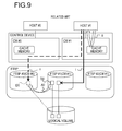
Here, descriptions will be made on a configuration and operations of a storage system in which the AST technology is employed with reference to FIG. 9. A storage system illustrated in FIG. 9 includes two host computers (hereinafter, simply referred to as hosts) #0 and #1, a parent pool FTRP (flexible tier pool) including a plurality of storage devices (SSDs, HDDs, or the like), and a control device.
The control device is provided between the hosts # 0 and #1 and the parent pool FTRP, and includes two control units CMs (Controller Modules) #0 and #1, each of which performs an input/output control for the parent pool FTRP in response to input/output requests from the hosts # 0 and #1. Each of the CMs # 0 and #1 is provided with a cache memory which temporarily holds a data unit stored in the parent pool FTRP. The CMs # 0 and #1 are communicably connected with each other.
In the parent pool FTRP, a plurality of child pools FTSPs (flexible tier sub pools) implemented with different levels of RAIDs (redundant arrays of inexpensive disks), or a plurality of child pools FTSPs implemented with RAIDs constructed of different types of disks are prepared using the plurality of storage devices to form storage tiers.
In the parent pool FTRP illustrated in FIG. 9, three child pools FTSP #0, FTSP #1, and FTSP #2 are prepared, the child pool FTSP # 0 is under the control of the CM # 0, and the child pools FTSP #1 and FTSP #2 are under the control of the CM # 1. The child pool FTSP #0 has the highest performance (shortest response time), the child pool FTSP #1 has the second highest performance (second shortest response time), and the child pool FTSP # 2 has the lowest performance (longest response time). For example, the child pool FTSP #0 is an SSD, the child pool FTSP #1 is a RAID1 or an online HDD, and the child pool FTSP # 2 is a RAID5 or a near line HDD.
In the storage system, a volume (logical volume) of the AST is associated with the parent pool FTRP. A finely divided unit TPPE (thin provisioning pool element) is allocated to the volume of the AST from the child pools FTSP # 0, FTSP # 1, and FTSP # 2 in a stage where the volume is written into the parent pool FTRP. The unit is called a chunk, and a plurality of chunks collected into a single group is called an FTRPE, a chunk collection, a chunk group, a data block, a transfer unit, or a data unit.
The performance information is collected for each data unit. The performance information is, for example, an access frequency (number of accesses per unit time) of the data unit. It is determined, based on the collected access frequency, whether each data unit is to be transferred to a child pool residing in a higher tier, to a child pool residing in a lower tier, or is not to be transferred to another child pool. Each data unit is transferred and relocated depending on the determination result. For example, as illustrated in FIG. 9, when the access frequency of data unit D0 placed on the child pool FTSP # 1 becomes greater than a predetermined threshold value, the data unit D0 is transferred from the child pool FTSP # 1 to the child pool FTSP # 0 of the higher tier to be relocated in the child pool FTSP # 0, as illustrated by an arrow A0.
As a related technology, there has been known a cache control device that controls a cache operation of a storage system including a plurality of cache modules connected with each other and storage modules connected to the cache modules. In the cache control device, a page having a high possibility of receiving an access request among the pages managed by a certain cache module is held in a memory of the cache module. In the meantime, a page having a low possibility of receiving the access request is allocated to another cache module.
As another related technology, there has been known a technology that migrates a virtual logical volume to a real logical volume, in a case where a use rate of the virtual logical volume exceeds a threshold value and a physical storage area corresponding to a storage area of the virtual logical volume is managed by another control unit.
Related technologies are disclosed in, for example, Japanese Laid-Open Patent Publication No. 2000-181763 and Japanese Laid-Open Patent Publication No. 2011-13800.
When access frequencies are gathered as the performance information and more frequently accessed data units are simply transferred to the higher tier to be relocated as described above, performance degradation may be caused in the following cases (1) and (2).
(1) A case where a straight access is made to the data unit before the data unit is transferred and a cross access is made to the data unit after the data unit is transferred:
For example, as illustrated in FIG. 9, in a state where the data unit D0 before being transferred is placed on the child pool FTSP # 1 under the control of the CM # 1, the straight access to the data unit D0 is made when an input/output request for the data unit D0 is received from the host #1 (see an arrow i in FIG. 9). It is assumed that this state is changed to a state where the data unit D0 is transferred to the child pool FTSP # 0 of the higher tier under the control of the CM # 0 to be relocated (see the arrow A0 in FIG. 9). When an input/output request for the data unit D0 after having been transferred is received from the host # 1, the cross access including communications between the CM # 1 and CM # 0 is made to the data unit D0 residing on the child pool FTSP #0 (see an arrow ii in FIG. 9). Different from the straight access, the cross access includes communications between the CMs so that a response becomes slower when the cross access occurs, thereby causing a performance degradation.
(2) A case where an access to a disk hardly occurs due to a high cache hit rate of the data unit intended to be transferred.
For example, as illustrated in FIG. 9, in a state where the data unit D0 which is a target data unit to be transferred is held in a cache memory of the CM # 1, the cache hit rate of the target data unit D0 to be transferred is increased when an input/output request for the data unit D0 is received from the host #1 (see an arrow iii). Accordingly, access to the child pool FTSP #1 hardly occurs. When this state is changed to a state where the data unit D0 is transferred to the child pool FTSP # 0 of the higher tier under the control of the CM # 0 to be relocated (see the arrow A0 in FIG. 9), the data unit D0 is not hit in the cache memory of the CM # 1, thereby causing a performance degradation.
SUMMARY
According to an aspect of the present invention, provided is a control device including a processor. The processor is configured to collect plural types of performance information regarding a first data unit. The processor is configured to determine, on basis of the collected plural types of performance information, whether to transfer the first data unit from a first storage device which is under control of a first controller to a second storage device which is positioned as higher than the first storage device. The processor is configured to transfer the first data unit from the first storage device to the second storage device depending on a result of the determination.
The object and advantages of the invention will be realized and attained by means of the elements and combinations particularly pointed out in the claims. It is to be understood that both the foregoing general description and the following detailed description are exemplary and explanatory and are not restrictive of the invention, as claimed.
BRIEF DESCRIPTION OF DRAWINGS
FIG. 1 is a block diagram illustrating a hardware configuration of a storage system including a control device according to a first embodiment;
FIG. 2 is a block diagram illustrating a functional configuration of the control device illustrated in FIG. 1;
FIG. 3 is a flowchart illustrating operations of a collection part in the control device illustrated in FIG. 2;
FIG. 4 is a diagram illustrating an example of a first table;
FIG. 5 is a diagram illustrating an example of a second table;
FIG. 6 is a flowchart illustrating operations of a transfer determination part, a transfer control part, a switching determination part, and a switching control part in the control device illustrated in FIG. 2;
FIG. 7 is a flowchart illustrating a first process of FIG. 6;
FIG. 8 is a flowchart illustrating a second process of FIG. 6; and
FIG. 9 is a diagram illustrating a configuration and operations of the storage system in which an AST technology is employed.
DESCRIPTION OF EMBODIMENTS
Hereinafter descriptions will be made in detail on a control device and a storage system according to embodiments with reference to accompanying drawings. However, the embodiments are illustrative only and do not intend to exclude various modifications and application of technologies not explicitly described in the embodiment. That is, the embodiments may be practiced in various modifications without departing from a gist of the present disclosure. Further, each drawing does not intend to include solely the constitutional elements illustrated in the drawing, and may include other functions. Also, embodiments may be suitably combined within a range in which processing contents are not inconsistent with each other.
First Embodiment
As described above with reference to FIG. 9, in the case of (1) or (2) described above, simply transferring more frequently accessed data unit to the higher tier to be relocated is likely to cause degradation in performance.
Accordingly, a control device according to a first embodiment controls a placement state of data of a predetermined access unit in storage devices residing in a plurality of tiers for each data unit and collects plural types of performance information for each data unit (collection part). The control device determines whether each data unit is to be transferred from a storage device storing each data unit to a storage device of a higher tier on the basis of the plurality of types of collected performance information (transfer determination part), and transfers each data unit between the storage devices of the plurality of tiers depending on the determination result (transfer control part).
For example, an access frequency used for both a transfer determination whether to transfer the data unit to a higher tier and a transfer determination whether to transfer the data unit to a lower tier as will be described below is contained in the plural types of performance information collected for each data unit. For example, at least one of a straight access rate and a cache hit rate used for the transfer determination whether to transfer the data unit to a higher tier as will be described below is contained in the plural types of performance information. In the present embodiment, descriptions will be made on a case where both of the straight access rate and the cache hit rate are collected as the plural types of performance information.
The access frequency which is the minimum required performance information is collected for each data unit and registered in a first table T1 (see FIG. 4), as will be described below. The straight access rate and the cache hit rate that correspond to detailed performance information are collected for a data unit having a relatively high access frequency and a high possibility of transferring to a higher tier, and registered in a second table T2 (see FIG. 5), as will be described below.
In this case, when the data unit having a relatively high access frequency exists, the control device according to the present embodiment does not immediately determine that the data unit is to be transferred to a higher tier and performs a transfer determination whether to transfer the data unit to a higher tier after securing a memory area (see a second table information storage area 122 b of FIG. 2) which stores the second table T2 and collecting the detailed performance information described above. When the access frequency of the data unit is reduced, the control device according to the present embodiment releases the memory area secured for the second table T2. In this way, the control device according to the present embodiment may collect the straight access rate and the cache hit rate that correspond to the detailed performance information, while suppressing an increase of the memory capacity required for securing the second table T2 to the minimum.
A case where the straight access rate collected for the data unit is high even though the access frequency collected for the data unit is high is considered as corresponding to the case (1) described above. In this case, the control device according to the present embodiment determines that the degradation in performance may be caused when the data unit is transferred to a higher tier, and determines that the data unit is not to be transferred to a higher tier.
A case where the cache hit rate collected for the data unit is high even though the access frequency collected for the data unit is high is considered as corresponding to the case (2) described above. In this case, the control device according to the present embodiment determines that the degradation in performance may be caused when the data unit is transferred to a higher tier, and determines that the data unit is not to be transferred to a higher tier.
Descriptions will be made on a hardware configuration of a storage system 1 including a control device 10 according to the first embodiment with reference to the block diagram illustrated in FIG. 1.
The AST technology is employed in the storage system 1 illustrated in FIG. 1, and the storage system 1 includes two hosts 2 (host # 0 and host #1), a parent pool 3 (FTRP; disk enclosure) including, for example, a plurality of storage devices (SSDs, HDDs, or the like), and a control device 10 including two CMs 12 (CM # 0 and CM #1).
In the parent pool 3 (FTRP), a plurality of child pools 30, 31, and 32 (FTSPs) implemented with different levels of RAIDs, or a plurality of child pools 30, 31, and 32 (FTSPs) implemented with RAIDs constructed of different types of disks are prepared using, for example, a plurality of storage devices (SSDs, HDDs, or the like) to form storage tiers.
In the parent pool 3 illustrated in FIG. 1, three child pools 30, 31, and 32 (plural types of storage devices; FTSPs # 0, #1, #2) are prepared and, for example, the child pool 30 is under the control of the CM # 0 and the child pools 31 and 32 are under the control of the CM # 1. The child pool 30 has the highest performance (shortest response time), the child pool 31 has the second highest performance (second shortest response time), and the child pool 32 has the lowest performance (longest response time). For example, the child pool 30 is an SSD, the child pool 31 is a RAID1 or an online HDD, and the child pool 32 is a RAID5 or a near line HDD.
Similarly to an example illustrated in FIG. 9, also in the storage system 1 according to the present embodiment, a volume (logical volume) of the AST is associated with the parent pool 3. A finely divided unit TPPE is allocated to the volume of the AST from the child pools 30, 31, and 32 in a stage where the volume is written into the parent pool 3. The unit is called a chunk. A plurality of chunks collected into a single group correspond to data of a predetermined access unit, and is called an FTRPE, a chunk collection, a chunk group, a data block, a transfer unit, or a data unit. Hereinafter, the data of a predetermined access unit is referred to as a data unit in the present embodiment.
The control device 10 according to the present embodiment is provided between the hosts # 0 and #1 and the parent pool 3. The control device 10 includes two channel adapters (CAs) 11 and two control units 12 (CM # 0 and CM #1).
The CAs 11 are interfaces connected to the hosts 2 to control communications with the hosts 2. The CAs 11 are provided to the hosts # 0 and #1, respectively.
The CMs 12 (computers) perform an input/output control to the parent pool 3 in accordance with input/output requests (I/O commands) from the hosts # 0 and #1, respectively. Each of the CMs 12 includes a central processing unit (CPU) 121, a memory 122, a device adapter (DA) 123, and a front-end router (FRT) 124.
The memory 122 may include, for example, a random access memory (RAM), an HDD, and an SSD. The memory 122 serves as a cache memory temporarily holding a data unit stored in the parent pool 3 when an access to the parent pool 3 (child pools 30, 31, and 32) is made. Further, the memory 122 serves as a main memory at the time when the CPU 121 executes an arithmetic processing. In the memory 122, a first table information storage area 122 a (see FIG. 2) for storing information for a first table T1 (see FIG. 4) is secured and the second table information storage area 122 b (see FIG. 2) for storing information for the second table T2 (see FIG. 5) is secured as necessary. A cache area 122 c serving as the cache memory is also secured in the memory 122.
Further, a first, second, third, fourth, and fifth threshold values to be described below may be set and stored in the memory 122 in advance. In the memory 122, a control program executed by the CPU 121 may be stored in order for the CPU 121 to serve as a collection part 121 a, a transfer determination part 121 b, a transfer control part 121 c, a switching determination part 121 d, and a switching control part 121 e to be described below with reference to FIG. 2. The first to the fifth threshold values may be set in a form of being incorporated in the control program.
The control program is provided in a form of being recorded in a computer-readable recording medium such as a flexible disk, a compact disc (CD) such as CD-ROM, CD-R, and CD-RW, a digital versatile disc (DVD) such as DVD-ROM, DVD-RAM, DVD-R, DVD-RW, DVD+R, and DVD+RW, and a Blu-ray disk. In this case, the CPU 121 uses the program in such a way that the program is read from the recording medium and the read program is transmitted to an internal storage device (for example, memory 122) or an external storage device to be stored therein.
The DA 123 is an interface connected with the parent pool 3 to control an access to the parent pool 3 (child pools 30, 31, and 32).
The FRT 124 is an interface connected with an FRT 124 of another CM 12 through a communication path to control communications between the CMs 12. The CM # 0 and CM # 1 are communicably connected with each other through the FRT 124.
Next, descriptions will be made on a functional configuration of the CM 12 of the control device 10 illustrated in FIG. 1 with reference to the block diagram illustrated in FIG. 2. The functional configuration illustrated in FIG. 2 is provided in at least one of the two CMs 12. As illustrated in FIG. 2, the CPU 121 in the CM 12 executes the control program to function as the collection part 121 a, the transfer determination part 121 b, the transfer control part 121 c, the switching determination part 121 d, and the switching control part 121 e. At this time, the first table T1 is spread on the memory 122 on the basis of information contained in the first table information storage area 122 a, and the second table T2 is also spread on the memory 122 on the basis of information contained in the second table information storage area 122 b. The first to the fifth threshold values on the memory 122 are referenced as well as the first table T1 and the second table T2 spread on the memory 122.
Descriptions will be made on the first table T1, the second table T2, and the first to the fifth threshold values on the memory 122.
The first table T1 is a performance information management table (see FIG. 4) that stores the minimum required performance information such as the access frequency collected by the collection part 121 a for each data unit. The access frequency is the number of accesses to each data unit per unit time. The performance information (access frequency) stored in the first table T1 is updated by the collection part 121 a at the time when processing according to an I/O command from the host 2 is completed.
The second table T2 is a performance information management table (see FIG. 5) that stores detailed performance information such as the straight access rate and the cache hit rate collected by the collection part 121 a for each data unit. The straight access rate is a ratio of the number of memory accesses (see the arrow i in FIG. 9) directly made to each data unit without using communications between the CMs to the total number of accesses to each data unit. The cache hit rate is a ratio of the number of cache hits (the accessed data unit exists on the cache memory 122 c; see the arrow iii in FIG. 9) to the total number of accesses to each data unit. The performance information (straight access rate and cache hit rate) stored in the second table T2 is also updated by the collection part 121 a at the time when processing according to the I/O command from the host 2 is completed.
The first threshold value is a predetermined threshold value for switching determination to be compared with the access frequency by the switching determination part 121 d to be described below. The first threshold value is used for determining whether to perform a determination by the transfer determination part 121 b using either only the first table T1 or both of the first table T1 and the second table T2.
The second threshold value is a predetermined threshold value for higher tier transfer determination to be compared with the access frequency by the transfer determination part 121 b to be described below when determining whether to transfer each data unit to a higher tier.
The third threshold value is a predetermined threshold value for lower tier transfer determination to be compared with the access frequency by the transfer determination part 121 b when determining whether to transfer each data unit to a lower tier.
The magnitude relation between the first threshold value, the second threshold value, and the third threshold value to be compared with the access frequency as described above is as follows;
second threshold value>first threshold value>third threshold value
The fourth threshold value is a predetermined threshold value of cache hit rate to be compared with the cache hit rate by the transfer determination part 121 b when determining whether to transfer each data unit to a higher tier.
The fifth threshold value is a predetermined threshold value of straight access rate to be compared with the straight access rate by the transfer determination part 121 b when determining whether to transfer each data unit to a higher tier.
Next, descriptions will be made on functions as the collection part 121 a, the transfer determination part 121 b, the transfer control part 121 c, the switching determination part 121 d, and the switching control part 121 e implemented by the CPU 121.
The collection part 121 a collects, as the plural types of performance information regarding a data unit accessed by the host 2, the access frequency of the data unit, the straight access rate to the data unit, and the cache hit rate of the data unit.
When the determination is made using only the first table T1 for the data unit, the collection part 121 a collects only the access frequency and stores the access frequency in the first table T1. When the determination is made using both of the first table T1 and the second table T2 for the data unit, the collection part 121 a collects and stores the access frequency in the first table T1, and collects and stores the straight access rate and the cache hit rate in the second table T2.
The transfer determination part 121 b refers to both of the first table T1 and the second table T2 when determining whether to transfer the data unit to a higher tier. The transfer determination part 121 b determines that a data unit is to be transferred to a higher tier when the access frequency exceeds the second threshold value (threshold value for higher tier transfer determination), the straight access rate is less than the fifth threshold value (threshold value of straight access rate), and the cache hit rate is less than the fourth threshold value (threshold value of cache hit rate). Even though the access frequency exceeds the second threshold value, the transfer determination part 121 b determines that the data unit is not to be transferred to a higher tier when either the straight access rate is equal to or greater than the fifth threshold value or the cache hit rate is equal to or greater than the fourth threshold value.
The transfer determination part 121 b refers to the first table T1 when performing a determination whether to transfer the data unit to a lower tier. The transfer determination part 121 b determines the data unit is to be transferred to a lower tier when the access frequency is less than the third threshold value (threshold value for lower tier transfer determination) which is smaller than the second threshold value (threshold value for higher tier transfer determination).
The transfer control part 121 c transfers the data unit, which is determined to be transferred, between the child pools 30, 31, and 32 of the plurality of tiers depending on the result of determination by the transfer determination part 121 b.
The switching determination part 121 d determines whether the access frequency is larger than the first threshold value (threshold value for switching determination) which is smaller than the second threshold value (threshold value for higher tier transfer determination) and larger than the third threshold value (threshold value for lower tier transfer determination).
When it is determined by the switching determination part 121 d that the access frequency is greater than the first threshold value, the switching control part 121 e switches to a state where the transfer determination part 121 b performs the determination whether to transfer the data unit to a higher tier using both of the first table T1 and the second table T2. When it is determined by the switching determination part 121 d that the access frequency is equal to or less than the first threshold value, the switching control part 121 e switches to a state where the transfer determination part 121 b performs the determination whether to transfer the data unit to a lower tier using only the first table T1.
The switching control part 121 e secures, in the second table T2, an area for storing the straight access rate and the cache hit rate regarding the data unit when switching from the state where the lower tier transfer determination is performed to the state where the higher tier transfer determination is performed. The switching control part 121 e releases, in the second table T2, the area for storing the straight access rate and the cache hit rate regarding the data unit when switching from the state where the higher tier transfer determination is performed to the state where the lower tier transfer determination is performed.
Next, descriptions will be made on the operations of the control device 10 according to the present embodiment, which has the configuration and functions as described above, with reference to FIG. 3 to FIG. 8.
First, descriptions will be made on the operations of the collection part 121 a, the first table T1, and the second table T2 with reference to FIG. 3 to FIG. 5. FIG. 3 is a flowchart illustrating the operations (table update process) of the collection part 121 a in the CM 12 illustrated in FIG. 2. FIG. 4 and FIG. 5 are diagrams illustrating examples of the first table T1 and second table T2, respectively.
When the host 2 issues an I/O command and the CM 12 receives the I/O command from the host 2 (S11), the command is analyzed in the CM 12 (S12). In this case, what portion of which volume residing in the parent pool 3, to which the I/O command is issued, may be determined based on information such as an host logical unit (OLU) number or a host logical block address (OLBA) included in the I/O command.
Accordingly, the collection part 121 a may determine whether an access to a data unit targeted by the I/O command is a straight access. The collection part 121 a may calculate the straight access rate described above for the data unit on the basis of the determination result. Since the collection part 121 a may recognize the data unit targeted by the I/O command, the collection part 121 a may also calculate the access frequency with respect to the data unit. The calculation of the straight access rate on the basis of the analysis result obtained at S12 is executed in a case where the determination is performed for the data unit by using both of the first table T1 and the second table T2.
Processing corresponding to the I/O command is executed in accordance with the analysis result at S12 (S13). In this case, since it is determined whether the data unit targeted by the I/O command exists on the cache memory (cache area 122 c of the memory 122), that is, whether a cache hit has occurred, the collection part 121 a may calculate the cache hit rate for the data unit. The calculation of the cache hit rate on the basis of the processing performed at S13 is executed in a case where the determination is performed for the data unit by using both of the first table T1 and the second table T2.
When the processing corresponding to the I/O command is completed, the collection part 121 a updates the first table T1 and the second table T2 on the basis of the performance information collected for the data unit targeted by I/O command at the time of completion of the processing (S14). Information about at which location (offset) of the first table T1 or the second table T2 the performance information of the data unit is stored and registered is held in a table (not illustrated) for managing the chunk (TPPE) described above. When the performance information is updated, the collection part 121 a refers to the table to determine an area for storing the performance information of the data unit.
As illustrated in FIG. 4, the first table T1 holds only an I/O count corresponding to the access frequency for each data unit (FTRPE). As illustrated in FIG. 5, the second table T2 holds the cache hit rate and the straight access rate for each data unit (FTRPE) which is subjected to the higher tier transfer determination.
Next, descriptions will be made on the operations of the transfer determination part 121 b, the transfer control part 121 c, the switching determination part 121 d, and the switching control part 121 e in the CM 12 illustrated in FIG. 2 with reference to the flowcharts illustrated in FIG. 6 to FIG. 8. FIG. 6 is a flowchart illustrating the operations. FIG. 7 and FIG. 8 are flowcharts illustrating a first process (processing at S23) and a second process (processing at S25) of FIG. 6, respectively.
The CPU 121 of the CM 12 regularly executes the control program such that the processes illustrated in FIG. 6 to FIG. 8 are performed. As illustrated in FIG. 6, the CPU 121 selects and refers to a single data unit not yet processed (S21), and determines whether the data unit is managed only by the first table T1 (S22). When it is determined that the data unit is managed only by the first table T1 (“YES” at S22), the CPU 121 executes the first process to be described below with reference to FIG. 7 (S23). Thereafter, the CPU 121 determines whether all of the data units have been processed (S24).
When it is determined that the data unit is not managed only by the first table T1, that is, when the data unit is managed by both of the first table T1 and the second table T2 (“NO” at S22), the CPU 121 executes the second process to be described below with reference to FIG. 8 (S25). Thereafter, the CPU 121 determines whether all of the data units have been processed (S24).
When it is determined that some of the data units have not been processed (“NO” at S24), the process returns to S21. When it is determined that all of the data units have been processed (“YES” at S24), the transfer control part 121 c transfers and relocates the data unit, which is determined to be transferred in the first process or the second process, between the child pools 30, 31, and 32 in the plurality of tiers (S26). Thereafter, the CPU 121 ends the process.
Subsequently, descriptions will be made on the first process performed at S23 of FIG. 6 with reference to the flowchart illustrated in FIG. 7. As described above, the first process is performed when the target data unit is managed only by the first table T1. A data unit which is processed for the first time is handled as being managed only by the first table T1.
In the first process, the switching determination part 121 d refers to the first table T1 and determines whether the access frequency of the data unit is greater than the first threshold value (threshold value for switching determination) (S31). When it is determined that the access frequency is greater than the first threshold value (“YES” at S31), the switching control part 121 e determines whether a free space available for an area storing the straight access rate and the cache hit rate of the data unit remains in the second table T2 (second table information storage area 122 b) (S32).
When it is determined that a free space available for the area does not remain in the second table T2 (“NO” at S32), the process returns to S24 of FIG. 6. When it is determined that a free space remains in the second table T2 (“YES” at S32), the switching control part 121 e switches to a state where the transfer determination part 121 b determines whether to transfer the data unit to a higher tier using both of the first table T1 and the second table T2 (S33). Thereafter, the process returns to S24 of FIG. 6.
As described above, according to the present embodiment, the data unit of which the access frequency exceeds the first threshold value for the first time becomes a data unit to be subjected to the second process without being determined as the data unit to be transferred to a higher tier immediately, even though the access frequency exceeds the second threshold value (threshold value for higher tier transfer determination). That is, the data unit becomes a target data unit to be managed and determined by both of the first table T1 and the second table T2.
When it is determined that the access frequency of the data unit is equal to or less than the first threshold value (threshold value for switching determination) (“NO” at S31), the transfer determination part 121 b performs the determination whether the data unit is to be transferred to a lower tier (S34). In this case, the transfer determination part 121 b refers to the first table T1 and determines whether the access frequency of the data unit is less than the third threshold value (threshold value for lower tier transfer determination).
When it is determined that the access frequency of the data unit is less than the third threshold value (“YES” at S34), the transfer determination part 121 b determines that the data unit is to be transferred to a lower tier (S35) and then, the process returns to S24 of FIG. 6. When it is determined that the access frequency of the data unit is equal to or greater than the third threshold value (“NO” at S34), the process returns to S24 immediately.
Next, descriptions will be made on the second process performed at S25 of FIG. 6 with reference to the flowchart illustrated in FIG. 8. As described above, the second process is performed when the target data unit is managed by both of the first table T1 and the second table T2.
In the second process, the transfer determination part 121 b refers to the first table T1 and determines whether the access frequency of the data unit is greater than the second threshold value (threshold value for higher tier transfer determination) (S41). When it is determined that the access frequency is greater than the second threshold value (“YES” at S41), the transfer determination part 121 b refers to the second table T2 and determines whether the cache hit rate of the data unit is less than the fourth threshold value (threshold value of cache hit rate) (S42).
When it is determined that the cache hit rate of the data unit is equal to or greater than the fourth threshold value (“NO” at S42), it is considered as a situation that corresponds to the case (2) described above even though the access frequency of the data unit exceeds the second threshold value. Accordingly, the transfer determination part 121 b determines the data unit is not to be transferred to a higher tier, and the process returns to S24 of FIG. 6.
When it is determined that the cache hit rate of the data unit is less than the fourth threshold value (“YES” at S42), the transfer determination part 121 b refers to the second table T2, and determines whether the cache hit rate of the data unit is less than the fifth threshold value (threshold value of straight access rate) (S43).
When it is determined that the cache hit rate of the data unit is equal to or greater than the fifth threshold value (“NO” at S43), it is considered as a situation that corresponds to the case (1) described above even though the access frequency of the data unit exceeds the second threshold value. Accordingly, the transfer determination part 121 b determines the data unit is not to be transferred to a higher tier, and the process returns to S24 of FIG. 6.
When it is determined that the straight access rate of the data unit is less than the fifth threshold value (“YES” at S43), it does not correspond to any of the case (1) and case (2). Accordingly, the transfer determination part 121 b determines that the data unit is to be transferred to a higher tier (S44), and the process returns to S24 of FIG. 6.
When it is determined that the access frequency of the data unit is equal to or less than the second threshold value (“NO” at S41), the transfer determination part 121 b determines whether the access frequency of the data unit is greater than the first threshold value (threshold value for switching determination) (S45). When it is determined that the access frequency is greater than the first threshold value (“YES” at S45), the process returns to S24 of FIG. 6 immediately.
When it is determined that the access frequency is equal to or less than the first threshold value (“NO” at S45), the switching control part 121 e switches to a state where the transfer determination part 121 b determines whether to transfer the data unit to a higher tier using only the first table T1 (S46). In this case, the switching control part 121 e releases, in the second table T2, the area storing the straight access rate and the cache hit rate of the data unit. Thereafter, the process returns to S24 of FIG. 6.
As described above, according to the present embodiment, when the access frequency of the data unit managed by both the first table T1 and the second table T2 exceeds the second threshold value, it is further determined whether the cache hit rate of the data unit is lower than the fourth threshold value, and the straight access rate of the data unit is lower than the fifth threshold value. Only when the cache hit rate and the straight access rate of the data unit are determined to be lower than the respective threshold values, the data unit is determined to be transferred to a higher tier.
When the cache hit rate is high, the access frequency of the disk is low so that a problem of access path hardly occurs. Therefore, in FIG. 8, the cache hit rate is checked first and only when the cache hit rate is less than the fourth threshold value (that is, when the cache hit rate is low), the straight access rate is checked.
As described above, the following effect may be obtained by the control device 10 or the storage system 1 according to the present embodiment. That is, when a data unit of which the access frequency is relatively high exists, the data unit is not immediately determined to be transferred, and the determination whether to transfer the data unit to a higher tier is performed after collecting the cache hit rate and the straight access rate in the area secured in the second table T2. When the access frequency of the data unit is reduced, the area secured in the second table T2 is released. Accordingly, the straight access rate and the cache hit rate may be collected while suppressing the increase of the memory capacity required for securing the second table T2 to the minimum.
A case where the straight access rate collected for the data unit is high even though the access frequency collected for the data unit is high is considered as corresponding to the case (1) described above. In this case, it is determined that the performance degradation may be caused when the data unit is transferred to a higher tier, and thus, the data unit is not determined to be transferred to a higher tier.
A case where the cache hit rate collected for the data unit is high even though the access frequency collected for the data unit is high is considered as corresponding to the case (2) described above. In this case, it is determined that the performance degradation may be caused when the data unit is transferred to a higher tier, and thus, the data unit is not determined to be transferred to a higher tier.
Therefore, by the control device 10 or the storage system 1 according to the present embodiment, the data may be relocated between the tiers without causing the performance degradation of the storage system 1.
Although the first embodiment has been described in detail, the present disclosure is not limited to the specific embodiment, and may be embodied in various modifications and/or through any changes that may be made thereto without departing from a gist of the present disclosure.
For example, although descriptions have been made on a case where the number of storage devices (child pools) is three in the first embodiment, the present disclosure is not limited thereto, and the number of storage devices (child pools) may be two, or four or more. Although descriptions have been made on a case where the number of CMs is two in the first embodiment, the present disclosure is not limited thereto, and the number of CMs may be one, or three or more.
Although descriptions have been made on a case where three types of the access frequency, the cache hit rate, and the straight access rate are collected and used as the plural types of performance information in the first embodiment, the present disclosure is not limited thereto. For example, as the plural types of performance information, either two types of the access frequency and the cache hit rate or two types of the access frequency and the straight access rate may be collected and used, and otherwise, four or more types of performance information may be collected and used. In both cases, a similar effect to the first embodiment may be obtained.
When the two types of the access frequency and the cache hit rate are used as the plural types of performance information, S43 of the flowchart illustrated in FIG. 8 may be omitted. When the two types of the access frequency and the straight access rate are used as the plural types of performance information, S42 of the flowchart illustrated in FIG. 8 may be omitted.
Although descriptions have been made on a case where the straight access rate is included as one of the plural types of performance information in the first embodiment, the same effect as the first embodiment may be obtained when a cross access ratio is used instead of the straight access rate. Here, the cross access ratio (see the arrow ii in FIG. 9) refers to a ratio of the number of accesses that are indirectly made to each data unit through communications between the CMs to the total number of accesses to each data unit.
All examples and conditional language recited herein are intended for pedagogical purposes to aid the reader in understanding the invention and the concepts contributed by the inventor to furthering the art, and are to be construed as being without limitation to such specifically recited examples and conditions, nor does the organization of such examples in the specification relate to an illustrating of the superiority and inferiority of the invention. Although the embodiments of the present invention have been described in detail, it should be understood that the various changes, substitutions, and alterations could be made hereto without departing from the spirit and scope of the invention.

Claims (20)

What is claimed is:
1. A control device for transferring data units between storage devices, the control device comprising:
a memory; and
a processor coupled to the memory, the processor configured to
collect plural types of performance information including an access frequency of a first data unit, a straight access rate of the first data unit, and a cache hit rate of the first data unit, the access frequency being a number of accesses to the first data unit per unit time, the straight access rate being a ratio of a number of straight accesses to a total number of accesses, and the cache hit rate being a ratio of a number of cache hit accesses to a total number of accesses,
compare the access frequency with a first threshold value,
when it is determined that the access frequency exceeds the first threshold value, determine, on a basis of a relationship between the straight access rate and the cache hit rate, whether to transfer the first data unit from a first storage device which is under control of a first controller to a second storage device which is positioned as a higher tier storage device than the first storage device, and
transfer the first data unit from the first storage device to the second storage device depending on a result of the determination, such that the first data unit is relocated to the higher tier storage device based on the relationship between the access frequency, the straight access rate, and the cache hit rate.
2. The control device according to claim 1, wherein
the straight accesses are accesses performed without involving a second controller different from the first controller, and
the processor is configured to
determine that the first data unit is to be transferred to the second storage device when the access frequency exceeds the first threshold value and the straight access rate is less than a second threshold value, and
determine that the first data unit is not to be transferred to the second storage device when the straight access rate is equal to or greater than the second threshold value even though the access frequency exceeds the first threshold value.
3. The control device according to claim 1, wherein
the cache hit accesses are accesses to the first data unit performed without accessing the first storage device, and
the processor is configured to
determine that the first data unit is to be transferred to the second storage device when the access frequency exceeds the first threshold value and the cache hit rate is less than a second threshold value, and
determine that the first data unit is not to be transferred to the second storage device when the cache hit rate is equal to or greater than the second threshold value even though the access frequency exceeds the first threshold value.
4. The control device according to claim 1, wherein
the straight accesses are accesses performed without involving a second controller different from the first controller, and the cache hit accesses are accesses to the first data unit performed without accessing the first storage device, and
the processor is configured to
determine that the first data unit is to be transferred to the second storage device when the access frequency exceeds the first threshold value, the straight access rate is less than a second threshold value, and the cache hit rate is less than a third threshold value, and
determine that the first data unit is not to be transferred to the second storage device when either the straight access rate is equal to or greater than the second threshold value or the cache hit rate is equal to or greater than the third threshold value even though the access frequency exceeds the first threshold value.
5. The control device according to claim 4, wherein the processor is configured to
determine that the first data unit is to be transferred to a third storage device which is positioned as a lower tier storage device than the first storage device when the access frequency is less than a fourth threshold value which is smaller than the first threshold value.
6. The control device according to claim 5, wherein the processor is configured to
store the access frequency in a first table,
store the straight access rate and the cache hit rate in a second table,
determine whether the access frequency is larger than a fifth threshold value which is smaller than the first threshold value and larger than the fourth threshold value,
switch, when it is determined that the access frequency is larger than the fifth threshold value, to a first state where whether to transfer the first data unit to the second storage device is determined on basis of both the first table and the second table, and
switch, when it is determined that the access frequency is equal to or less than the fifth threshold value, to a second state where whether to transfer the first data unit to the third storage device is determined on basis of only the first table.
7. The control device according to claim 6, wherein the processor is configured to
secure, in the second table, an area for storing the straight access rate and the cache hit rate when switching from the second state to the first state.
8. The control device according to claim 7, wherein the processor is configured to
release the area when switching from the first state to the second state.
9. A storage system, comprising:
a first storage device which is under control of a first controller;
a second storage device which is positioned as a higher tier storage device than the first storage device; and
a control device for transferring data units between the first and second storage devices, the control device including:
a memory; and
a processor coupled to the memory, the processor configured to
collect plural types of performance information including an access frequency of a first data unit, a straight access rate of the first data unit, and a cache hit rate of the first data unit, the access frequency being a number of accesses to the first data unit per unit time, the straight access rate being a ratio of a number of straight accesses to a total number of accesses, and the cache hit rate being a ratio of a number of cache hit accesses to a total number of accesses,
compare the access frequency with a first threshold value,
when it is determined that the access frequency exceeds the first threshold value, determine, on a basis of a relationship between the straight access rate and the cache hit rate, whether to transfer the first data unit from the first storage device to the second storage device, and
transfer the first data unit from the first storage device to the second storage device depending on a result of the determination, such that the first data unit is relocated to the higher tier storage device based on the relationship between the access frequency, the straight access rate, and the cache hit rate.
10. The storage system according to claim 9, wherein
the straight accesses are accesses performed without involving a second controller different from the first controller, and
the processor is configured to
determine that the first data unit is to be transferred to the second storage device when the access frequency exceeds the first threshold value and the straight access rate is less than a second threshold value, and
determine that the first data unit is not to be transferred to the second storage device when the straight access rate is equal to or greater than the second threshold value even though the access frequency exceeds the first threshold value.
11. The storage system according to claim 9, wherein
the cache hit accesses are accesses to the first data unit performed without accessing the first storage device, and
the processor is configured to
determine that the first data unit is to be transferred to the second storage device when the access frequency exceeds the first threshold value and the cache hit rate is less than a second threshold value, and
determine that the first data unit is not to be transferred to the second storage device when the cache hit rate is equal to or greater than the second threshold value even though the access frequency exceeds the first threshold value.
12. The storage system according to claim 9, wherein
the straight accesses are accesses performed without involving a second controller different from the first controller, the cache hit accesses are accesses to the first data unit performed without accessing the first storage device, and
the processor is configured to
determine that the first data unit is to be transferred to the second storage device when the access frequency exceeds the first threshold value, the straight access rate is less than a second threshold value, and the cache hit rate is less than a third threshold value, and
determine that the first data unit is not to be transferred to the second storage device when either the straight access rate is equal to or greater than the second threshold value or the cache hit rate is equal to or greater than the third threshold value even though the access frequency exceeds the first threshold value.
13. The storage system according to claim 12, further comprising:
a third storage device which is positioned as a lower tier storage device than the first storage device,
wherein the processor is configured to determine that the first data unit is to be transferred to the third storage device when the access frequency is less than a fourth threshold value which is smaller than the first threshold value.
14. The storage system according to claim 13, wherein the processor is configured to
store the access frequency in a first table,
store the straight access rate and the cache hit rate in a second table,
determine whether the access frequency is larger than a fifth threshold value which is smaller than the first threshold value and larger than the fourth threshold value,
switch, when it is determined that the access frequency is larger than the fifth threshold value, to a first state where whether to transfer the first data unit to the second storage device is determined on basis of both the first table and the second table, and
switch, when it is determined that the access frequency is equal to or less than the fifth threshold value, to a second state where whether to transfer the first data unit to the third storage device is determined on basis of only the first table.
15. The storage system according to claim 14, wherein
the processor is configured to
secure, in the second table, an area for storing the straight access rate and the cache hit rate when switching from the second state to the first state.
16. The storage system according to claim 15, wherein
the processor is configured to
release the area when switching from the first state to the second state.
17. A non-transitory computer-readable recording medium having stored therein a program that causes a computer to execute a process for transferring data units between storage devices, the process comprising:
collecting plural types of performance information including an access frequency of a first data unit, a straight access rate of the first data unit, and a cache hit rate of the first data unit, the access frequency being a number of accesses to the first data unit per unit time, the straight access rate being a ratio of a number of straight accesses to a total number of accesses, and the cache hit rate being a ratio of a number of cache hit accesses to a total number of accesses;
comparing the access frequency with a first threshold value;
when it is determined at the comparing that the access frequency exceeds the first threshold value, determining, on a basis of a relationship between the straight access rate and the cache hit rate, whether to transfer the first data unit from a first storage device which is under control of a first controller to a second storage device which is positioned as a higher tier storage device than the first storage device; and
transferring the first data unit from the first storage device to the second storage device depending on a result of the determination, such that the first data unit is relocated to the higher tier storage device based on the relationship between the access frequency, the straight access rate, and the cache hit rate.
18. The non-transitory computer-readable recording medium according to claim 17, wherein
the straight accesses are accesses performed without involving a second controller different from the first controller, and the cache hit accesses are accesses performed without accessing the first storage device, and
the process comprises:
determining that the first data unit is to be transferred to the second storage device when the access frequency exceeds the first threshold value, the straight access rate is less than a second threshold value, and the cache hit rate is less than a third threshold value; and
determining that the first data unit is not to be transferred to the second storage device when either the straight access rate is equal to or greater than the second threshold value or the cache hit rate is equal to or greater than the third threshold value even though the access frequency exceeds the first threshold value.
19. The non-transitory computer-readable recording medium according to claim 18, the process further comprising:
determining that the first data unit is to be transferred to a third storage device which is positioned as a lower tier storage device than the first storage device when the access frequency is less than a fourth threshold value which is smaller than the first threshold value.
20. The non-transitory computer-readable recording medium according to claim 19, the process further comprising:
storing the access frequency in a first table;
storing the straight access rate and the cache hit rate in a second table;
determining whether the access frequency is larger than a fifth threshold value which is smaller than the first threshold value and larger than the fourth threshold value;
switching, when it is determined that the access frequency is larger than the fifth threshold value, to a first state where whether to transfer the first data unit to the second storage device is determined on a basis of both the first table and the second table; and
switching, when it is determined that the access frequency is equal to or less than the fifth threshold value, to a second state where whether to transfer the first data unit to the third storage device is determined on a basis of only the first table.
US14/822,171 2014-09-18 2015-08-10 Control device and storage system Active 2036-06-09 US9904474B2 (en)

Applications Claiming Priority (2)

Application Number Priority Date Filing Date Title
JP2014-189928 2014-09-18
JP2014189928A JP6350162B2 (en) 2014-09-18 2014-09-18 Control device

Publications (2)

Publication Number Publication Date
US20160085446A1 US20160085446A1 (en) 2016-03-24
US9904474B2 true US9904474B2 (en) 2018-02-27

Family

ID=55525753

Family Applications (1)

Application Number Title Priority Date Filing Date
US14/822,171 Active 2036-06-09 US9904474B2 (en) 2014-09-18 2015-08-10 Control device and storage system

Country Status (2)

Country Link
US (1) US9904474B2 (en)
JP (1) JP6350162B2 (en)

Cited By (2)

* Cited by examiner, † Cited by third party
Publication number Priority date Publication date Assignee Title
WO2019245612A1 (en) * 2018-06-19 2019-12-26 Western Digital Technologies, Inc. Balanced caching
CN113553195A (en) * 2021-09-22 2021-10-26 苏州浪潮智能科技有限公司 A method, apparatus, device and readable medium for sharing memory pool resources

Families Citing this family (6)

* Cited by examiner, † Cited by third party
Publication number Priority date Publication date Assignee Title
US10496511B2 (en) * 2016-09-26 2019-12-03 Oracle International Corporation Frequent items detection in data sets
US10474588B1 (en) * 2017-04-05 2019-11-12 EMC IP Holding Company LLC Method and system for memory-based data caching
US11372760B2 (en) 2018-07-26 2022-06-28 Sony Semiconductor Solutions Corporation Storage control device for controlling cache memory based on access frequencies
CN111857544B (en) * 2019-04-26 2024-05-17 富联精密电子(天津)有限公司 Storage resource management device and management method
CN115079933B (en) * 2021-03-12 2024-05-24 戴尔产品有限公司 Fast caching system based on data relations
JP2023069701A (en) * 2021-11-08 2023-05-18 株式会社日立製作所 Data control device, storage system, and data control device

Citations (7)

* Cited by examiner, † Cited by third party
Publication number Priority date Publication date Assignee Title
JP2000181763A (en) 1998-12-17 2000-06-30 Fujitsu Ltd Cache control apparatus and method for dynamically managing data between cache modules
US20100332778A1 (en) 2009-06-30 2010-12-30 Fujitsu Limited Control unit for storage device and method for controlling storage device
US20120303929A1 (en) * 2011-05-27 2012-11-29 International Business Machines Corporation Systems, methods, and physical computer storage media to optimize data placement in multi-tiered storage systems
US20120317355A1 (en) * 2011-06-07 2012-12-13 Hitachi, Ltd. Storage apparatus and data management method
US20130024650A1 (en) * 2011-07-18 2013-01-24 Lsi Corporation Dynamic storage tiering
US20150039825A1 (en) * 2013-08-02 2015-02-05 Seagate Technology Llc Federated Tiering Management
US20150121024A1 (en) * 2013-10-28 2015-04-30 Lenovo Enterprise Solutions (Singapore) Ptw. Ltd. Operating A Memory Management Controller

Family Cites Families (4)

* Cited by examiner, † Cited by third party
Publication number Priority date Publication date Assignee Title
JPH04165541A (en) * 1990-10-30 1992-06-11 Hitachi Ltd File rearranging method
JP2006301820A (en) * 2005-04-19 2006-11-02 Hitachi Ltd Storage system and storage system data migration method
JP5000234B2 (en) * 2006-08-24 2012-08-15 株式会社日立製作所 Control device
US9626110B2 (en) * 2013-02-22 2017-04-18 Hitachi, Ltd. Method for selecting a page for migration based on access path information and response performance information

Patent Citations (9)

* Cited by examiner, † Cited by third party
Publication number Priority date Publication date Assignee Title
JP2000181763A (en) 1998-12-17 2000-06-30 Fujitsu Ltd Cache control apparatus and method for dynamically managing data between cache modules
US20020108020A1 (en) 1998-12-17 2002-08-08 Riichiro Take Cache controlling apparatus for dynamically managing data between cache modules and method thereof
US20100332778A1 (en) 2009-06-30 2010-12-30 Fujitsu Limited Control unit for storage device and method for controlling storage device
JP2011013800A (en) 2009-06-30 2011-01-20 Fujitsu Ltd Control part and control method for storage device
US20120303929A1 (en) * 2011-05-27 2012-11-29 International Business Machines Corporation Systems, methods, and physical computer storage media to optimize data placement in multi-tiered storage systems
US20120317355A1 (en) * 2011-06-07 2012-12-13 Hitachi, Ltd. Storage apparatus and data management method
US20130024650A1 (en) * 2011-07-18 2013-01-24 Lsi Corporation Dynamic storage tiering
US20150039825A1 (en) * 2013-08-02 2015-02-05 Seagate Technology Llc Federated Tiering Management
US20150121024A1 (en) * 2013-10-28 2015-04-30 Lenovo Enterprise Solutions (Singapore) Ptw. Ltd. Operating A Memory Management Controller

Cited By (3)

* Cited by examiner, † Cited by third party
Publication number Priority date Publication date Assignee Title
WO2019245612A1 (en) * 2018-06-19 2019-12-26 Western Digital Technologies, Inc. Balanced caching
US11188474B2 (en) 2018-06-19 2021-11-30 Western Digital Technologies, Inc. Balanced caching between a cache and a non-volatile memory based on rates corresponding to the cache and the non-volatile memory
CN113553195A (en) * 2021-09-22 2021-10-26 苏州浪潮智能科技有限公司 A method, apparatus, device and readable medium for sharing memory pool resources

Also Published As

Publication number Publication date
JP2016062315A (en) 2016-04-25
US20160085446A1 (en) 2016-03-24
JP6350162B2 (en) 2018-07-04

Similar Documents

Publication Publication Date Title
US9904474B2 (en) Control device and storage system
US8850152B2 (en) Method of data migration and information storage system
US9229653B2 (en) Write spike performance enhancement in hybrid storage systems
JP6409613B2 (en) Information processing apparatus, multipath control method, and multipath control program
US9128855B1 (en) Flash cache partitioning
US9658796B2 (en) Storage control device and storage system
EP2711841A1 (en) Data processing method, device and system based on block storage
US8775766B2 (en) Extent size optimization
US20170123699A1 (en) Storage control device
US20160224274A1 (en) Storage device and storage system
US8904119B2 (en) Method and structures for performing a migration of a logical volume with a serial attached SCSI expander
US9547460B2 (en) Method and system for improving cache performance of a redundant disk array controller
US20170060774A1 (en) Storage control device
CN104951243A (en) Storage expansion method and device in virtualized storage system
US8713257B2 (en) Method and system for shared high speed cache in SAS switches
US9547443B2 (en) Method and apparatus to pin page based on server state
US9253276B2 (en) Multi-protocol bridge with integrated performance accelerating cache
US10481805B1 (en) Preventing I/O request timeouts for cloud-based storage systems
US20130031320A1 (en) Control device, control method and storage apparatus
KR101569049B1 (en) Pass through storage devices
US11016692B2 (en) Dynamically switching between memory copy and memory mapping to optimize I/O performance
US10942857B1 (en) Dynamically adjusting a number of memory copy and memory mapping windows to optimize I/O performance
US9977624B2 (en) Storage control apparatus and storage control method
US20130151808A1 (en) Allocation device, allocation method and storage device
JP2012003567A (en) Storage management device

Legal Events

Date Code Title Description
AS Assignment

Owner name: FUJITSU LIMITED, JAPAN

Free format text: ASSIGNMENT OF ASSIGNORS INTEREST;ASSIGNORS:KUMABE, TAKURO;KOBAYASHI, AKIHITO;SAKAI, MOTOHIRO;AND OTHERS;SIGNING DATES FROM 20150727 TO 20150730;REEL/FRAME:036321/0215

STCF Information on status: patent grant

Free format text: PATENTED CASE

MAFP Maintenance fee payment

Free format text: PAYMENT OF MAINTENANCE FEE, 4TH YEAR, LARGE ENTITY (ORIGINAL EVENT CODE: M1551); ENTITY STATUS OF PATENT OWNER: LARGE ENTITY

Year of fee payment: 4

FEPP Fee payment procedure

Free format text: MAINTENANCE FEE REMINDER MAILED (ORIGINAL EVENT CODE: REM.); ENTITY STATUS OF PATENT OWNER: LARGE ENTITY