US9904221B2 - Preheating device, fixing system, and image forming apparatus - Google Patents
Preheating device, fixing system, and image forming apparatus Download PDFInfo
- Publication number
- US9904221B2 US9904221B2 US15/590,611 US201715590611A US9904221B2 US 9904221 B2 US9904221 B2 US 9904221B2 US 201715590611 A US201715590611 A US 201715590611A US 9904221 B2 US9904221 B2 US 9904221B2
- Authority
- US
- United States
- Prior art keywords
- continuous paper
- recording medium
- inverting
- fixing
- roller
- Prior art date
- Legal status (The legal status is an assumption and is not a legal conclusion. Google has not performed a legal analysis and makes no representation as to the accuracy of the status listed.)
- Expired - Fee Related
Links
Images


Classifications
-
- G—PHYSICS
- G03—PHOTOGRAPHY; CINEMATOGRAPHY; ANALOGOUS TECHNIQUES USING WAVES OTHER THAN OPTICAL WAVES; ELECTROGRAPHY; HOLOGRAPHY
- G03G—ELECTROGRAPHY; ELECTROPHOTOGRAPHY; MAGNETOGRAPHY
- G03G15/00—Apparatus for electrographic processes using a charge pattern
- G03G15/20—Apparatus for electrographic processes using a charge pattern for fixing, e.g. by using heat
- G03G15/2003—Apparatus for electrographic processes using a charge pattern for fixing, e.g. by using heat using heat
- G03G15/2014—Apparatus for electrographic processes using a charge pattern for fixing, e.g. by using heat using heat using contact heat
- G03G15/2017—Structural details of the fixing unit in general, e.g. cooling means, heat shielding means
- G03G15/2021—Plurality of separate fixing and/or cooling areas or units, two step fixing
-
- G—PHYSICS
- G03—PHOTOGRAPHY; CINEMATOGRAPHY; ANALOGOUS TECHNIQUES USING WAVES OTHER THAN OPTICAL WAVES; ELECTROGRAPHY; HOLOGRAPHY
- G03G—ELECTROGRAPHY; ELECTROPHOTOGRAPHY; MAGNETOGRAPHY
- G03G15/00—Apparatus for electrographic processes using a charge pattern
- G03G15/20—Apparatus for electrographic processes using a charge pattern for fixing, e.g. by using heat
- G03G15/2003—Apparatus for electrographic processes using a charge pattern for fixing, e.g. by using heat using heat
- G03G15/2014—Apparatus for electrographic processes using a charge pattern for fixing, e.g. by using heat using heat using contact heat
- G03G15/2064—Apparatus for electrographic processes using a charge pattern for fixing, e.g. by using heat using heat using contact heat combined with pressure
-
- G—PHYSICS
- G03—PHOTOGRAPHY; CINEMATOGRAPHY; ANALOGOUS TECHNIQUES USING WAVES OTHER THAN OPTICAL WAVES; ELECTROGRAPHY; HOLOGRAPHY
- G03G—ELECTROGRAPHY; ELECTROPHOTOGRAPHY; MAGNETOGRAPHY
- G03G15/00—Apparatus for electrographic processes using a charge pattern
- G03G15/20—Apparatus for electrographic processes using a charge pattern for fixing, e.g. by using heat
- G03G15/2003—Apparatus for electrographic processes using a charge pattern for fixing, e.g. by using heat using heat
- G03G15/2014—Apparatus for electrographic processes using a charge pattern for fixing, e.g. by using heat using heat using contact heat
- G03G15/2039—Apparatus for electrographic processes using a charge pattern for fixing, e.g. by using heat using heat using contact heat with means for controlling the fixing temperature
- G03G15/205—Apparatus for electrographic processes using a charge pattern for fixing, e.g. by using heat using heat using contact heat with means for controlling the fixing temperature specially for the mode of operation, e.g. standby, warming-up, error
-
- G—PHYSICS
- G03—PHOTOGRAPHY; CINEMATOGRAPHY; ANALOGOUS TECHNIQUES USING WAVES OTHER THAN OPTICAL WAVES; ELECTROGRAPHY; HOLOGRAPHY
- G03G—ELECTROGRAPHY; ELECTROPHOTOGRAPHY; MAGNETOGRAPHY
- G03G15/00—Apparatus for electrographic processes using a charge pattern
- G03G15/22—Apparatus for electrographic processes using a charge pattern involving the combination of more than one step according to groups G03G13/02 - G03G13/20
- G03G15/23—Apparatus for electrographic processes using a charge pattern involving the combination of more than one step according to groups G03G13/02 - G03G13/20 specially adapted for copying both sides of an original or for copying on both sides of a recording or image-receiving material
- G03G15/231—Arrangements for copying on both sides of a recording or image-receiving material
- G03G15/232—Arrangements for copying on both sides of a recording or image-receiving material using a single reusable electrographic recording member
- G03G15/234—Arrangements for copying on both sides of a recording or image-receiving material using a single reusable electrographic recording member by inverting and refeeding the image receiving material with an image on one face to the recording member to transfer a second image on its second face, e.g. by using a duplex tray; Details of duplex trays or inverters
- G03G15/237—Arrangements for copying on both sides of a recording or image-receiving material using a single reusable electrographic recording member by inverting and refeeding the image receiving material with an image on one face to the recording member to transfer a second image on its second face, e.g. by using a duplex tray; Details of duplex trays or inverters the image receiving member being in form of a continuous web
-
- G—PHYSICS
- G03—PHOTOGRAPHY; CINEMATOGRAPHY; ANALOGOUS TECHNIQUES USING WAVES OTHER THAN OPTICAL WAVES; ELECTROGRAPHY; HOLOGRAPHY
- G03G—ELECTROGRAPHY; ELECTROPHOTOGRAPHY; MAGNETOGRAPHY
- G03G15/00—Apparatus for electrographic processes using a charge pattern
- G03G15/65—Apparatus which relate to the handling of copy material
- G03G15/6517—Apparatus for continuous web copy material of plain paper, e.g. supply rolls; Roll holders therefor
- G03G15/652—Feeding a copy material originating from a continuous web roll
-
- F—MECHANICAL ENGINEERING; LIGHTING; HEATING; WEAPONS; BLASTING
- F28—HEAT EXCHANGE IN GENERAL
- F28F—DETAILS OF HEAT-EXCHANGE AND HEAT-TRANSFER APPARATUS, OF GENERAL APPLICATION
- F28F5/00—Elements specially adapted for movement
- F28F5/02—Rotary drums or rollers
-
- G—PHYSICS
- G03—PHOTOGRAPHY; CINEMATOGRAPHY; ANALOGOUS TECHNIQUES USING WAVES OTHER THAN OPTICAL WAVES; ELECTROGRAPHY; HOLOGRAPHY
- G03G—ELECTROGRAPHY; ELECTROPHOTOGRAPHY; MAGNETOGRAPHY
- G03G15/00—Apparatus for electrographic processes using a charge pattern
- G03G15/01—Apparatus for electrographic processes using a charge pattern for producing multicoloured copies
- G03G15/0105—Details of unit
-
- G—PHYSICS
- G03—PHOTOGRAPHY; CINEMATOGRAPHY; ANALOGOUS TECHNIQUES USING WAVES OTHER THAN OPTICAL WAVES; ELECTROGRAPHY; HOLOGRAPHY
- G03G—ELECTROGRAPHY; ELECTROPHOTOGRAPHY; MAGNETOGRAPHY
- G03G15/00—Apparatus for electrographic processes using a charge pattern
- G03G15/01—Apparatus for electrographic processes using a charge pattern for producing multicoloured copies
- G03G15/0142—Structure of complete machines
- G03G15/0178—Structure of complete machines using more than one reusable electrographic recording member, e.g. one for every monocolour image
- G03G15/0189—Structure of complete machines using more than one reusable electrographic recording member, e.g. one for every monocolour image primary transfer to an intermediate transfer belt
-
- G—PHYSICS
- G03—PHOTOGRAPHY; CINEMATOGRAPHY; ANALOGOUS TECHNIQUES USING WAVES OTHER THAN OPTICAL WAVES; ELECTROGRAPHY; HOLOGRAPHY
- G03G—ELECTROGRAPHY; ELECTROPHOTOGRAPHY; MAGNETOGRAPHY
- G03G15/00—Apparatus for electrographic processes using a charge pattern
- G03G15/06—Apparatus for electrographic processes using a charge pattern for developing
- G03G15/08—Apparatus for electrographic processes using a charge pattern for developing using a solid developer, e.g. powder developer
-
- G—PHYSICS
- G03—PHOTOGRAPHY; CINEMATOGRAPHY; ANALOGOUS TECHNIQUES USING WAVES OTHER THAN OPTICAL WAVES; ELECTROGRAPHY; HOLOGRAPHY
- G03G—ELECTROGRAPHY; ELECTROPHOTOGRAPHY; MAGNETOGRAPHY
- G03G15/00—Apparatus for electrographic processes using a charge pattern
- G03G15/14—Apparatus for electrographic processes using a charge pattern for transferring a pattern to a second base
- G03G15/16—Apparatus for electrographic processes using a charge pattern for transferring a pattern to a second base of a toner pattern, e.g. a powder pattern, e.g. magnetic transfer
- G03G15/1605—Apparatus for electrographic processes using a charge pattern for transferring a pattern to a second base of a toner pattern, e.g. a powder pattern, e.g. magnetic transfer using at least one intermediate support
- G03G15/161—Apparatus for electrographic processes using a charge pattern for transferring a pattern to a second base of a toner pattern, e.g. a powder pattern, e.g. magnetic transfer using at least one intermediate support with means for handling the intermediate support, e.g. heating, cleaning, coating with a transfer agent
-
- G—PHYSICS
- G03—PHOTOGRAPHY; CINEMATOGRAPHY; ANALOGOUS TECHNIQUES USING WAVES OTHER THAN OPTICAL WAVES; ELECTROGRAPHY; HOLOGRAPHY
- G03G—ELECTROGRAPHY; ELECTROPHOTOGRAPHY; MAGNETOGRAPHY
- G03G15/00—Apparatus for electrographic processes using a charge pattern
- G03G15/20—Apparatus for electrographic processes using a charge pattern for fixing, e.g. by using heat
- G03G15/2003—Apparatus for electrographic processes using a charge pattern for fixing, e.g. by using heat using heat
- G03G15/2014—Apparatus for electrographic processes using a charge pattern for fixing, e.g. by using heat using heat using contact heat
- G03G15/2053—Structural details of heat elements, e.g. structure of roller or belt, eddy current, induction heating
-
- G—PHYSICS
- G03—PHOTOGRAPHY; CINEMATOGRAPHY; ANALOGOUS TECHNIQUES USING WAVES OTHER THAN OPTICAL WAVES; ELECTROGRAPHY; HOLOGRAPHY
- G03G—ELECTROGRAPHY; ELECTROPHOTOGRAPHY; MAGNETOGRAPHY
- G03G15/00—Apparatus for electrographic processes using a charge pattern
- G03G15/22—Apparatus for electrographic processes using a charge pattern involving the combination of more than one step according to groups G03G13/02 - G03G13/20
- G03G15/23—Apparatus for electrographic processes using a charge pattern involving the combination of more than one step according to groups G03G13/02 - G03G13/20 specially adapted for copying both sides of an original or for copying on both sides of a recording or image-receiving material
- G03G15/231—Arrangements for copying on both sides of a recording or image-receiving material
-
- G—PHYSICS
- G03—PHOTOGRAPHY; CINEMATOGRAPHY; ANALOGOUS TECHNIQUES USING WAVES OTHER THAN OPTICAL WAVES; ELECTROGRAPHY; HOLOGRAPHY
- G03G—ELECTROGRAPHY; ELECTROPHOTOGRAPHY; MAGNETOGRAPHY
- G03G2215/00—Apparatus for electrophotographic processes
- G03G2215/00362—Apparatus for electrophotographic processes relating to the copy medium handling
- G03G2215/00535—Stable handling of copy medium
- G03G2215/00687—Handling details
- G03G2215/007—Inverter not for refeeding purposes
Definitions
- the present invention relates to a preheating device, a fixing system, and an image forming apparatus.
- a preheating device before a continuous recording medium on which an unfixed image, such as a toner image, is formed is introduced into a fixing device, a back surface of the recording medium on which the unfixed image is not formed is preheated.
- a transport state of the web is changed and adjusted by outputting the web in a state in which the web is wound around a turning bar disposed in a transport path.
- a preheating device including two first inverting members disposed at different positions while obliquely intersecting a feeding direction of a continuous recording medium on which an unfixed image is formed, the first inverting members inverting the recording medium by passing a back surface of the recording medium, on which the unfixed image is not formed, therealong before a fixing operation, and at least one heating rotating body disposed at a position further on an outside than a side edge portion of the recording medium in the feeding direction to preheat the recording medium before the fixing operation by passing a portion of the back surface of the recording medium present between the two first inverting members so that the portion of the back surface is wound around the heating rotating body.
- FIG. 1 is a schematic explanatory view illustrating a configuration of an image forming apparatus according to a first exemplary embodiment
- FIG. 2 is a schematic explanatory view illustrating a structure of a fixing system in the image forming apparatus illustrated in FIG. 1 ;
- FIG. 3 is a schematic perspective view illustrating a structure of a preheating device in the fixing system illustrated in FIG. 2 ;
- FIG. 4 is a schematic perspective view illustrating a structure of an inverting device in the fixing system illustrated in FIG. 2 ;
- FIG. 5 is a schematic explanatory view illustrating a state of the fixing system of FIG. 2 when viewed from above;
- FIG. 6 is a schematic explanatory view illustrating a configuration of an image forming apparatus according to a second exemplary embodiment
- FIG. 7 is a schematic explanatory view illustrating a structure of a fixing system in the image forming apparatus illustrated in FIG. 6 ;
- FIG. 8 is a schematic perspective view illustrating a structure of a preheating device in the fixing system illustrated in FIG. 7 ;
- FIG. 9 is a schematic explanatory view illustrating a state of the fixing system of FIG. 7 when viewed from above;
- FIG. 10 is a schematic explanatory view illustrating a structure of a fixing system according to a third exemplary embodiment
- FIG. 11 is a schematic explanatory view illustrating a state of the fixing system of FIG. 10 when viewed from above;
- FIG. 12 is a schematic explanatory view illustrating a configuration of an image forming apparatus according to a fourth exemplary embodiment
- FIG. 13 is a schematic explanatory view illustrating a structure of a fixing system in the fourth exemplary embodiment
- FIG. 14 is a schematic explanatory view illustrating a state of the fixing system of FIG. 13 when viewed from above;
- FIG. 15 is a schematic explanatory view illustrating a structure of a fixing system according to a fifth exemplary embodiment
- FIG. 16 is a schematic explanatory view illustrating a state of the fixing system of FIG. 15 when viewed from obliquely above;
- FIG. 17 is a schematic explanatory view illustrating a state of the fixing system of FIG. 15 when viewed from above;
- FIG. 18 is a schematic explanatory view illustrating another structure example of the preheating device in the fixing system illustrated in, for example, FIG. 2 .
- FIGS. 1 to 3 illustrate an image forming apparatus according to a first exemplary embodiment.
- FIG. 1 illustrates a general outline of the image forming apparatus
- FIG. 2 illustrates a fixing system provided in the image forming apparatus
- FIG. 3 illustrates a preheating device provided in the image forming apparatus or the fixing system.
- arrows with signs X, Y, and Z denote (the directions of) orthogonal coordinate axes representing the directions of width, height, and depth, respectively, of a three-dimensional space assumed in the figures.
- An image forming apparatus 1 forms an image made with toner of developer on continuous paper 9 serving as an example of a continuous recording medium wound in a roll form.
- the image forming apparatus 1 includes a supply device 11 that supplies continuous paper 9 , an image forming device 2 that forms a toner image serving as an example of an unfixed image on the continuous paper 9 supplied from the supply device 11 , a fixing system 4 that performs a fixing operation of fixing the toner image formed on the continuous paper 9 in the image forming device 2 after preheating, before the fixing operation, a back surface 9 b of the continuous paper 9 on which the toner image is not formed, and a storage device 16 that stores the continuous paper 9 after an image is formed thereon by the fixing operation in the fixing system 4 .
- the supply device 11 includes a pay-out roller 12 that pays out the continuous paper 9 wound in a roll form, an adjusting mechanism 13 that adjust a pay-out operation of the pay-out roller 12 , and an introduction transport roller pair 14 that transports the continuous paper 9 paid out through the adjusting mechanism 13 and supplies the continuous paper 9 to the image forming device 2 .
- the pay-out roller 12 is rotated in a pay-out direction by driving force received from an unillustrated driving device.
- the adjusting mechanism 13 includes two transport rollers 13 a and 13 b arranged in parallel and spaced from each other in a transport direction (feeding direction) A of the continuous paper 9 , an elevating roller 13 c that moves up and down almost along the gravitational direction between the two transport rollers 13 a and 13 b , and an unillustrated position sensor that detects that the elevating roller 13 c reaches specified positions in the up-down direction.
- the continuous paper 9 is supported while being laid between the two transport rollers 13 a and 13 b , and is transported in such a manner that the continuous paper 9 is pulled downward almost along the gravitational direction by the elevating roller 13 c between the transport rollers 13 a and 13 b and then turns back.
- the transport roller pair 14 is constituted of a rotating roller and a driven roller arranged in pressure contact with each other.
- the rotating roller is rotated in a direction corresponding to the transport direction A by driving force received from an unillustrated driving device, and the continuous paper 9 is thereby transported while passing through a pressure contact portion between these rollers.
- the transport roller pair 14 is disposed in the image forming device 2 .
- the continuous paper 9 is transported by the transport roller pair 14 when the pay-out roller 12 is stopped and the elevating roller 13 c of the adjusting mechanism 13 is moved to the lower specified position.
- the elevating roller 13 c starts moving up, and moves up to finally reach the upper specified position.
- the pay-out roller 12 rotates to pay out the continuous paper 9 .
- the elevating roller 13 c starts moving down, and moves down to finally reach the lower specified position.
- the pay-out roller 12 is stopped to discontinue paying-out of the continuous paper 9 .
- the amount of continuous paper 9 supplied to the image forming device 2 corresponds to the rotation amount of the transport roller pair 14 .
- the continuous paper 9 for example, a belt-shaped long continuous material made of paper such as high-quality paper or glassine paper, or synthetic resin, such as polypropylene, is used.
- label paper having a structure in which a surface base material (image forming surface) is provided on release paper with an adhesive layer interposed between is also used as the continuous paper 9 .
- the storage device 16 includes a take-up roller 17 that takes up the continuous paper 9 on which an image is formed, an adjusting mechanism 18 that adjusts a take-up operation of the take-up roller 17 , and an output transport roller pair 19 that transports the continuous paper 9 to the adjusting mechanism 18 after the image is formed on the continuous paper 9 .
- the take-up roller 17 is rotated in a take-up direction by driving force received from an unillustrated driving device.
- the adjusting mechanism 18 is constituted of two transport rollers 18 a and 18 b , an elevating roller 18 c , and a detector that detects upper and lower specified positions of the elevating roller 18 c , almost similarly to the adjusting mechanism 13 in the supply device 11 .
- the transport roller pair 19 has a structure almost similar to the transport roller pair 14 in the supply device 11 . In practice, the transport roller pair 19 is also disposed in the image forming device 2 , similarly to the transport roller pair 14 .
- the image forming device 2 forms toner images by using some or all of toners of four colors of yellow (Y), magenta (M), cyan (C), and black (K) on the basis of image information input from the outside through various units, and transfers the toner images on the continuous paper 9 .
- the image forming device 2 includes four image forming units 20 Y, 20 M, 20 C, and 20 K each of which forms a toner image of any one of the above four colors (Y, M, C, and K), and an intermediate transfer device 30 that holds color toner images formed by the image forming units 20 (Y, M, C, and K) and transports the color toner images to a second transfer position P 2 where the color toner images are finally transferred onto the continuous paper 9 .
- Each of the image forming units 20 includes a photoconductor drum 21 to be rotated in a predetermined direction (a direction shown by arrow B). Also, in each of the image forming units 20 (Y, M, C, and K), a charging device 22 , an exposure device 23 , a developing device 24 , and a cleaning device 26 are arranged around the photoconductor drum 21 .
- the charging device 22 charges a peripheral surface of the photoconductor drum 21 .
- the exposure device 23 forms an electrostatic latent image by exposing the charged peripheral surface of the photoconductor drum 21 to light based on the image information.
- the developing device 24 develops the electrostatic latent image formed on the peripheral surface of the photoconductor drum 21 with toner of developer to form a toner image.
- the cleaning device 26 removes and cleans off unwanted matter, such as toner, remaining on the peripheral surface of the photoconductor drum 21 .
- the developing device 24 is provided as four developing devices 24 Y, 24 M, 24 C, and 24 K.
- Each of the developing devices 24 Y, 24 M, 24 C, and 24 K stores toner of any one of the above four colors (Y, M, C, and K), and develops an electrostatic latent image of the corresponding color with the toner.
- the intermediate transfer device 30 is disposed below the four image forming units 20 (Y, M, C, and K).
- the intermediate transfer device 30 includes an intermediate transfer belt 31 that rotates in a direction of arrow C while passing through first transfer positions at photoconductor drums 21 in the image forming units 20 (Y, M, C, and K), plural support rollers 32 A to 32 E that support the intermediate transfer belt 31 rotatably, and first transfer devices 33 that first-transfer toner images on the photoconductor drums 21 onto an outer surface of the intermediate transfer belt 31 by, for example, an electrostatic action by pressing the outer surface of the intermediate transfer belt 31 against the first transfer positions on the photoconductor drums 21 in the image forming units 20 (Y, M, C, and K).
- the first transfer devices 33 are each shaped like a roller.
- the intermediate transfer device 30 further includes a second transfer device 35 shaped like, for example, a roller to second-transfer the toner images on the intermediate transfer belt 31 onto continuous paper 9 by, for example, an electrostatic action, and a cleaning device 36 that removes and cleans off unwanted matter, such as toner, remaining on the outer surface of the intermediate transfer belt 31 .
- a second transfer device 35 shaped like, for example, a roller to second-transfer the toner images on the intermediate transfer belt 31 onto continuous paper 9 by, for example, an electrostatic action
- a cleaning device 36 that removes and cleans off unwanted matter, such as toner, remaining on the outer surface of the intermediate transfer belt 31 .
- the support roller 32 A, the support roller 32 D, and the support roller 32 E are respectively structured as a driving roller, a tensioning roller, and a second-transfer backup roller.
- the second transfer device 35 is displaceable to move into contact with and apart from the intermediate transfer belt 31 supported by the second-transfer backup roller 32 E.
- the second transfer device 35 moves to a position in contact with the intermediate transfer belt 31 only during a period in which a second transfer operation is performed, and moves to a position separate from the intermediate transfer belt 31 during other necessary periods.
- the first transfer positions are positions where the photoconductor drums 21 are opposed to the first transfer devices 33 in the image forming units 20 (strictly, positions where the photoconductor drums 21 are in contact with the intermediate transfer belt 31 ).
- the second transfer position P 2 is a position where the intermediate transfer belt 31 is in opposed contact with the second transfer device 35 in the intermediate transfer device 30 .
- the fixing system 4 includes a fixing device 40 that performs a fixing operation of fixing a toner image formed as an unfixed image on continuous paper 9 by passing the continuous paper 9 therethrough, and a preheating device 5 disposed at a position upstream of the fixing device 40 in the feeding direction A of the continuous paper 9 to preheat, before the fixing operation, a back surface 9 b of the continuous paper 9 on which the toner image is not formed.
- the fixing system 4 is disposed between (the second transfer position P 2 in) the image forming device 2 and the storage device 16 .
- the fixing device 40 in the fixing system 4 includes at least a heating rotating body 41 and a pressurizing rotating body 42 , as illustrated in FIG. 1 .
- a two-dot chain line VL 1 in FIG. 2 is an imaginary straight line that connects the second transfer position P 2 in the image forming device 2 and a fixing nip FN (to be described later) serving as a fixing portion in the fixing device 40 in the shortest distance.
- the fixing device 40 of the first exemplary embodiment adopts a belt-shaped heating rotating body 41 and a roller-shaped pressurizing rotating body (pressurizing roller) 42 .
- the belt-shaped heating rotating body 41 is constituted of an endless heating belt 43 serving as a heating member, a fixing roller 44 serving as a pressing member, a first support roller 45 , an inner heating roller 46 , and a second support roller 47 , which are disposed to support the heating belt 43 while being in contact with an inner peripheral surface of the heating belt 43 , and an outer heating roller 48 in contact with a portion of an outer peripheral surface of the heating belt 43 between the first support roller 45 and the inner heating roller 46 to press the portion toward the inner peripheral surface of the heating belt 43 .
- the heating belt 43 of the heating rotating body 41 is in pressure contact with the pressurizing roller 42 at a portion of the heating belt 43 wound on an outer peripheral surface of the fixing roller 44 .
- the pressure contact portion between the heating belt 43 and the pressurizing roller 42 serves as a fixing nip FN for fixing the unfixed toner image formed on the continuous paper 9 by heating and pressurization.
- the heating belt 43 is composed of a belt base made of, for example, polyimide resin or polyamide resin, an elastic layer stacked on an outer peripheral surface of the belt base and made of, for example, silicone rubber, and a release layer stacked on a surface of the elastic layer and made of, for example, a tetrafluoroethylene perfluoroalkyl vinylether copolymer (PFA).
- a belt base made of, for example, polyimide resin or polyamide resin
- an elastic layer stacked on an outer peripheral surface of the belt base and made of, for example, silicone rubber
- a release layer stacked on a surface of the elastic layer and made of, for example, a tetrafluoroethylene perfluoroalkyl vinylether copolymer (PFA).
- PFA tetrafluoroethylene perfluoroalkyl vinylether copolymer
- the fixing roller 44 is constituted by a cylindrical member made of metal such as aluminum or stainless steel, and is rotated in a direction of arrow in FIG. 2 by an unillustrated driving unit.
- a heat source 49 A such as a halogen lamp, is disposed inside the fixing roller 44 , and heats the fixing roller 44 so that the surface temperature of the fixing roller 44 reaches a required temperature.
- the inner heating roller 46 is constituted by a cylindrical member made of metal such as aluminum or stainless steel.
- a heat source 49 B such as a halogen lamp, is disposed inside the inner heating roller 46 , and heats the inner heating roller 46 so that the surface temperature of the inner heating roller 46 reaches a required temperature.
- force is applied from an unillustrated elastic member, such as a spring, to the inner heating roller 46 so that the inner heating roller 46 is elastically displaceable from the inner side toward the outer side of the heating belt 43 , and this applies a required tension to the heating belt 43 .
- the outer heating roller 48 is constituted by a cylindrical member made of metal such as aluminum or stainless steel.
- a heat source 49 C such as a halogen lamp, is disposed inside the outer heating roller 48 , and heats the outer heating roller 48 so that the surface temperature of the outer heating roller 48 reaches a required temperature.
- the heating belt 43 stretched between the plural rollers is heated from the inner peripheral surface side and the outer peripheral surface side by the fixing roller 44 , the outer heating roller 48 , and the inner heating roller 46 while circularly rotating.
- the heating belt 43 is thereby heated so that the temperature of the outer peripheral surface thereof reaches a required temperature.
- the pressurizing roller 42 is constituted of a cylindrical roller base made of metal such as aluminum or stainless steel, an elastic layer stacked on an outer surface of the roller base and made of, for example, silicone rubber, and a release layer stacked on a surface of the elastic layer and made of, for example, PFA.
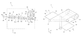
- the preheating device 5 includes two first inverting members 51 and 52 and a heating roller 53 serving as an example of a heating rotating body.
- the two first inverting members 51 and 52 are disposed at different positions to obliquely intersect the feeding direction A of the continuous paper 9 on which the toner image is formed, and invert the continuous paper 9 by passing a back surface 9 b of the continuous paper 9 , on which the toner image is not formed, therealong before the fixing operation.
- the heating roller 53 is disposed at a position further on an outside than side edge portions 9 c and 9 d of the continuous paper 9 in the feeding direction A, and preheats a portion of the back surface 9 b of the continuous paper 9 located between the first inverting members 51 and 52 before the fixing operation by passing the portion of the back surface 9 b along the heating roller 53 so that the portion of the back surface 9 b is wound around the heating roller 53 .
- the two first inverting members 51 and 52 are cylindrical members made of metal.
- the upstream-side first inverting member 51 disposed on the upstream side in the feeding direction A of the continuous paper 9 inverts the continuous paper 9 transported to the first inverting member 51 so that the continuous paper 9 is transported with the back surface 9 b being in contact with the outer peripheral surface of the heating roller 53 .
- the downstream-side first inverting member 52 disposed on the downstream side in the feeding direction A of the continuous paper 9 inverts the continuous paper 9 transported from the heating roller 53 to the first inverting member 52 so that the continuous paper 9 is transported with a front surface 9 a being opposed to the heating rotating body 41 (heating belt 43 ) in the fixing device 40 .
- the first inverting members 51 and 52 in the first exemplary embodiment are fixedly arranged to intersect the feeding direction A of the continuous paper 9 at an angle of 45 degrees.
- the upstream-side first inverting member 51 is disposed at a position on a relatively upper side of the downstream-side first inverting member 52 while intersecting the downstream-side first inverting member 52 .
- the upstream-side first inverting member 51 is used to introduce the continuous paper 9 sent in the preheating device 5 from the lower side thereof and to pass the continuous paper 9 on the upper side thereof.
- the downstream-side first inverting member 52 is disposed at a position on a relatively lower side of the upstream-side first inverting member 51 to substantially orthogonally intersect the upstream-side first inverting member 51 .
- the downstream-side first inverting member 52 is used to introduce the continuous paper 9 sent from the heating roller 53 from the lower side thereof and to pass the continuous paper 9 on the upper side thereof.
- the first inverting members 51 and 52 may be shaped like a barrel as a whole and be curved with an arc-shaped cross section only in a portion to be in contact with the continuous paper 9 .
- the shapes of other inverting members to be described later are similar to the shape of the first inverting members 51 and 52 .
- the heating roller 53 is disposed at a position spaced outward by a predetermined distance S 1 from one of the side edge portions 9 c and 9 d of the continuous paper 9 in the feeding direction A (the side edge portion 9 d in the first exemplary embodiment) in a state in which the axial direction of the heating roller 53 is substantially parallel to the feeding direction A of the continuous paper 9 .
- the heating roller 53 is constituted of a cylindrical roller base made of, for example, metal, and a heat source 54 , such as a halogen lamp, disposed in an internal space of the roller base.
- the roller base of the heating roller 53 is rotatably provided, and is driven to rotate along with the motion (transport movement) of the continuous paper 9 that passes while being wound around the heating roller 53 .
- the winding angle of the back surface 9 b of the continuous paper 9 around the heating roller 53 is set to be 180 degrees or more, for example, from the viewpoint of reliably heating the back surface 9 b of the continuous paper 9 .
- the winding angle of the back surface 9 b of the continuous paper 9 around the heating roller 53 is 90 degrees or more, this winding angle is more effective than when the winding angle is less than 90 degrees. That is, the winding angle less than 90 degrees is disadvantageous, for example, from the viewpoints of ensuring the heating length and restricting the installation space of the preheating device 5 from being increased by the difficulty in arranging the first inverting members 51 and 52 in a state in which the winding angle of the continuous paper 9 increases to an obtuse angle before and after winding around the heating roller 53 .
- This condition concerning the winding angle also applies to a heating rotating body such as a heating roller 57 to be described later.
- a one-dot chain line E in, for example, FIG. 5 shows almost the center position (center line) in the width direction of the continuous paper 9 that is being transported in the feeding direction A.
- an inverting device 6 is disposed upstream of the preheating device 5 in the feeding direction A of the continuous paper 9 .
- the inverting device 6 includes two second inverting members 61 and 62 and a relay roller 63 serving as an example of a relay rotating body.
- the second inverting members 61 and 62 are disposed at different positions further on the front side serving as the upstream side than the upstream-side first inverting member 51 of the preheating device 5 in the feeding direction A of the continuous paper 9 while obliquely intersecting the feeding direction A of the continuous paper 9 .
- the second inverting members 61 and 62 invert the continuous paper 9 by passing the back surface 9 b of the continuous paper 9 therealong.
- the relay roller 63 is disposed at a position further on the outside than the side edge portions 9 c and 9 d of the continuous paper 9 in the feeding direction A, and passes a portion of the back surface 9 b of the continuous paper 9 located between the second inverting members 61 and 62 so that the portion of the back surface 9 b is wound around the relay roller 63 .
- the two second inverting members 61 and 62 are cylindrical members made of metal.
- the upstream-side second inverting member 61 disposed on the upstream side in the feeding direction A of the continuous paper 9 inverts the continuous paper 9 transported to the second inverting member 61 to transport the continuous paper 9 in a state in which the back surface 9 b of the continuous paper 9 is in contact with an outer peripheral surface of the relay roller 63 .
- the downstream-side second inverting member 62 disposed on the downstream side in the feeding direction A of the continuous paper 9 inverts the continuous paper 9 transported from the relay roller 63 to the second inverting member 62 to transport the continuous paper 9 so that the front and back surfaces of the continuous paper 9 face in directions opposite from the directions when the continuous paper 9 is transported to the upstream-side second inverting member 61 .
- the second inverting member 62 inverts the continuous paper 9 so that the back surface 9 b of the continuous paper 9 faces up.
- the second inverting members 61 and 62 are fixedly arranged to intersect the feeding direction A of the continuous paper 9 at an angle of 45 degrees.
- the upstream-side second inverting member 61 is disposed at a position on a relatively lower side of the downstream-side second inverting member 62 while intersecting the downstream-side second inverting member 62 .
- the upstream-side second inverting member 61 is used to introduce the continuous paper 9 transported through the second transfer position P 2 in the image forming device 2 from the upper side of the second inverting member 61 and to pass the continuous paper 9 on the lower side thereof.
- the downstream-side second inverting member 62 is disposed at a position on a relatively upper side of the upstream-side second inverting member 61 while substantially orthogonally intersecting the upstream-side second inverting member 61 .
- the downstream-side second inverting member 62 is used to introduce the continuous paper 9 sent from the relay roller 63 from the upper side of the second inverting member 62 and to pass the continuous paper 9 on the lower side thereof.
- the relay roller 63 is disposed at a position spaced outward by a predetermined distance from one of the side edge portions 9 c and 9 d of the continuous paper 9 in the feeding direction A in a state in which the axial direction of the relay roller 63 is substantially parallel to the feeding direction A of the continuous paper 9 .
- the relay roller 63 is constituted by a cylindrical roller base made of, for example, metal.
- the relay roller 63 is rotatable, and is driven to rotate along with the motion (transport movement) of the continuous paper 9 that passes while being wound around the relay roller 63 .
- a toner image is formed as an unfixed image and is transferred onto continuous paper 9 in the image forming device 2 .
- each of the image forming units 20 (Y, M, C, and K)
- the peripheral surface of the rotating photoconductor drum 21 is charged to a required polarity and a required potential by the charging device 22
- the charged peripheral surface is exposed by the exposure device 23 on the basis of a color component obtained from (multicolor) image information, so that an electrostatic latent image of the color component is formed.
- the electrostatic latent image is developed with charged toner of the corresponding color by the developing device 24 (Y, M, C, or K), and is thereby visualized as a color toner image.
- color toner images formed on the photoconductor drums 21 in the respective image forming units 20 are first-transferred in order onto the rotating intermediate transfer belt 31 of the intermediate transfer device 30 by the transfer action of the first transfer devices 33 , and are then transported to the second transfer position P 2 .
- the toner images first-transferred on the intermediate transfer belt 31 are collectively second-transferred onto continuous paper 9 transported to the second transfer position P 2 by the transfer action of the second transfer device 35 .
- the continuous paper 9 paid out from the supply device 11 is transported by the transport roller pair 14 toward the second transfer position P 2 in operative association with the toner-image forming operation in the image forming device 2 .
- the elevating roller 13 c in the adjusting mechanism 13 starts moving up from the lower specified position, and moves up to finally reach the upper specified position, as described above.
- the pay-out roller 12 rotates to pay out the continuous paper 9 .
- the continuous paper 9 is continuously transported during the toner-image forming operation.
- the continuous paper 9 on which the toner image has been formed is sent out from the second transfer position P 2 , is transported toward the fixing system 4 , and is subjected to preheating and fixing of the toner image in the fixing system 4 .
- the continuous paper 9 sent out from the second transfer position P 2 is transported to pass through the inverting device 6 , the preheating device 5 , and the fixing device 40 in this order.
- the continuous paper 9 is sent into the inverting device 6 in a state in which the front surface 9 a having the toner image formed thereon faces up. Then, the continuous paper 9 is inverted, and is sent out from the inverting device 6 with the back surface 9 b facing up.
- the continuous paper 9 passes while the back surface 9 b is in contact with the surface of the upstream-side second inverting member 61 to be obliquely wound around the surface.
- the continuous paper 9 is thereby twisted 90 degrees and is inverted.
- the continuous paper 9 is sent out toward the relay roller 63 .
- the continuous paper 9 is transported along with the rotation of the relay roller 63 while the back surface 9 b is in contact with the relay roller 63 to be wound around the relay roller 63 from the lower side. Then, the continuous paper 9 is sent out to return to the downstream-side second inverting member 62 .
- the continuous paper 9 passes while the back surface 9 b is in contact with the surface of the downstream-side second inverting member 62 to be obliquely wound around the surface.
- the continuous paper 9 is thereby twisted 90 degrees, and is inverted.
- the continuous paper 9 is sent out from the inverting device 6 with the back surface 9 b facing up. After that, the continuous paper 9 is transported toward the preheating device 5 provided on the downstream side.
- the continuous paper 9 inverted in the inverting device 6 is sent into the preheating device 5 in the state where the back surface 9 b having no tone image faces up, and is preheated from the back surface 9 b before the fixing operation. Also, the continuous paper 9 is inverted, and is sent out from the preheating device 5 with the front surface 9 a facing up.
- the continuous paper 9 is passed while the back surface 9 b is in contact with the surface of the upstream-side first inverting member 51 to be obliquely wound therearound.
- the continuous paper 9 is thereby twisted 90 degrees and is inverted.
- the continuous paper 9 is sent out toward the heating roller 53 .
- the continuous paper 9 is transported along with the rotation of the heating roller 53 in the direction of arrow in FIG. 3 while the back surface 9 b is in contact with the heating roller 53 to be obliquely wound therearound from the upper side, and is sent out to return toward the downstream-side first inverting member 52 .
- the heated continuous paper 9 is passed while the back surface 9 b is in contact with the surface of the downstream-side first inverting member 52 to be obliquely wound therearound.
- the continuous paper 9 is thereby twisted 90 degrees and is inverted.
- the continuous paper 9 is sent out from the preheating device 5 with the front surface 9 a facing up, and is transported toward the fixing device 40 provided on the downstream side.
- the continuous paper 9 is heated from the back surface 9 b at a required temperature (for example, a temperature set within the range of 90° C. to 180° C.) by the heating roller 53 .
- the continuous paper 9 preheated in the preheating device 5 is sent into (the fixing nip FN of) the fixing device 40 in the state where the front surface 9 a having the toner image formed thereon faces up, is subjected to the fixing operation of the toner image, and is then sent out from the fixing device 40 .
- the continuous paper 9 is introduced into and transported through the fixing nip FN in a state where the front surface 9 a is in contact with the heating belt 43 of the heating rotating body 41 .
- the unfixed toner image on the continuous paper 9 is fixed by the fixing operation using heat and pressure at the fixing nip FN.
- the continuous paper 9 is preheated from the back surface 9 b in the preheating device 5 , the continuous paper 9 is subjected to a formal fixing operation at the fixing nip FN in a state where the toner image is starting to be melted by heating.
- fixing may be more quickly and reliably performed than when preheating is not performed.
- the continuous paper 9 is transported toward the storage device 16 by the transport roller pair 19 .
- the elevating roller 18 c of the adjusting mechanism 18 in the storage device 16 starts moving down from the upper specified position, and moves down to finally reach the lower specified position.
- the take-up roller 17 rotates to take up the continuous paper 9 .
- the continuous paper 9 is stored.
- the heating roller 53 of the preheating device 5 is disposed further on the outside than the side edge portion 9 d of the continuous paper 9 (see, for example, FIG. 5 ).
- FIGS. 6 to 8 illustrate an image forming apparatus according to a second exemplary embodiment.
- FIG. 6 illustrates a general outline of the image forming apparatus
- FIG. 7 illustrates a fixing system provided in the image forming apparatus
- FIG. 8 illustrates a preheating device provided in the image forming apparatus or the fixing system.
- an image forming apparatus 1 B includes a supply device 11 , an image forming device 2 , a fixing system 4 B, and a storage device 16 .
- the fixing system 4 B is partly different in structure from the fixing system 4 of the first exemplary embodiment, but the supply device 11 , the image forming device 2 , and the storage device 16 have the same structures.
- the fixing system 4 B of the second exemplary embodiment includes a fixing device 40 , a preheating device 5 B, and a guide roller 71 .
- the fixing device 40 has the same structure as that of the fixing device 40 in the fixing system 4 of the first exemplary embodiment ( FIG. 2 ).
- the preheating device 5 B includes two first inverting members 55 and 56 and a heating roller 57 serving as an example of a heating rotating body.
- the first inverting members 55 and 56 are disposed at different positions while obliquely intersecting the feeding direction A of continuous paper 9 on which a toner image is formed, and inverts the continuous paper 9 by passing a back surface 9 b of the continuous paper 9 , which does not have the toner image, therealong before a fixing operation.
- the heating roller 57 is disposed at a position further on an outside than side edge portions 9 c and 9 d of the continuous paper 9 in the feeding direction A, and preheats a portion of the back surface 9 b of the continuous paper 9 between the first inverting members 55 and 56 before the fixing operation by passing the portion of the back surface 9 b so that the portion of the back surface 9 b is wound around the heating roller 57 .
- a one-dot chain line VL 2 is an imaginary straight line that connects a second transfer position P 2 in the image forming device 2 and a fixing nip FN in the fixing device 40 in the shortest distance.
- the two first inverting members 55 and 56 have structures substantially similar to those of the first inverting member 51 and 52 in the preheating device 5 of the first exemplary embodiment. However, the first inverting members 55 and 56 are arranged in a slight different manner as follows because the guide roller 71 to be described later is disposed on the upstream side of the preheating device 5 B.
- first inverting members 55 and 56 in the second exemplary embodiment are fixedly arranged to intersect the feeding direction A of the continuous paper 9 at an angle of 45 degrees, the arrangement thereof is slightly different in the following points.
- the upstream-side first inverting member 55 on the upstream side in the feeding direction A of the continuous paper 9 is disposed at a position on a relatively upper side of the downstream-side first inverting member 56 provided on the downstream side, and intersects the feeding direction A.
- the upstream-side first inverting member 55 is used to introduce continuous paper 9 sent into the preheating device 5 B from the lower side of the first inverting member 55 and to pass the continuous paper 9 on the upper side thereof.
- downstream-side first inverting member 56 is disposed at a position on a relatively lower side of the upstream-side first inverting member 55 while being substantially parallel to the upstream-side first inverting member 55 .
- the downstream-side first inverting member 56 is used to introduce the continuous paper 9 sent from the heating roller 57 from the lower side of the first inverting member 56 and to pass the continuous paper 9 on the upper side thereof.
- the continuous paper 9 inverted and sent out by the downstream-side first inverting member 56 is sent out in a feeding direction directly opposite from the feeding direction A of the continuous paper 9 when the continuous paper 9 is sent to the upstream-side first inverting member 55 .
- the heating roller 57 is disposed at a position spaced outward by a predetermined distance S 2 from one of the side edge portions 9 c and 9 d of the continuous paper 9 in the feeding direction A (the side edge portion 9 d in the second exemplary embodiment) in a state in which the axial direction of the heating roller 57 is substantially parallel to the feeding direction A. While the distance S 2 at this time is equal to the distance S 1 of the heating roller 53 in the preheating device 5 of the first exemplary embodiment, it may be set at a different value.
- the heating roller 57 is constituted of a cylindrical roller base made of, for example, metal, and a heat source 58 , such as a halogen lamp, disposed in an internal space of the roller base.
- the roller base of the heating roller 57 is rotatable, and is driven to rotate along with the motion (transport movement) of the continuous paper 9 passing to be wound around the heating roller 57 .
- the winding angle of the back surface 9 b of the continuous paper 9 around the heating roller 57 is also set to be 180 degrees or more from the viewpoint of reliably heating the back surface 9 b of the continuous paper 9 .
- the fixing system 4 B includes a guide roller 71 serving as an example of a guide rotating body on the upstream side of the preheating device 5 B.
- the guide roller 71 guides the continuous paper 9 in a different direction by passing the back surface 9 b of the continuous paper 9 so that the back surface 9 b is wound around the guide roller 71 .
- the guide roller 71 is disposed at a front position upstream of the upstream-side first inverting member 55 , of the two first inverting members 55 and 56 of the preheating device 5 B, in the feeding direction A of the continuous paper 9 in a state in which the axial direction of the guide roller 71 orthogonally intersects the feeding direction A of the continuous paper 9 .
- the guide roller 71 is a cylindrical member made of metal.
- the guide roller 71 is rotatably disposed between the second transfer position P 2 in the image forming device 2 and the fixing device 40 and at a position closer to the fixing device 40 .
- the guide roller 71 in the second exemplary embodiment is used to guide and return the continuous paper 9 sent out from the second transfer position P 2 of the image forming device 2 toward the second transfer position P 2 by turning back and passing the continuous paper 9 while the back surface 9 b is wound in contact with the guide roller 71 .
- the continuous paper 9 is transported to the guide roller 71 in a state where the front surface 9 a on which a toner image is formed faces up, and is passed along the guide roller 71 so that the back surface 9 b is wound around the guide roller 71 .
- the continuous paper 9 is guided in a different direction that is directly opposite from the feeding direction A of the continuous paper 9 when the continuous paper 9 is sent out from the second transfer position P 2 and that returns the continuous paper 9 toward the second transfer position P 2 again (however, this direction is a part of the feeding direction A).
- the continuous paper 9 transported by the guide roller 71 to return toward the second transfer position P 2 is sent into the preheating device 5 B in a state where the back surface 9 b on which the toner image is not formed faces up.
- the continuous paper 9 is preheated from the back surface 9 b before the fixing operation, and is inverted.
- the continuous paper 9 is then sent out from the preheating device 5 B with the front surface 9 a facing up.
- the continuous paper 9 is passed while the back surface 9 b is in contact with the surface of the upstream-side first inverting member 55 to be obliquely wound therearound, is twisted 90 degrees, and is inverted. In this state, the continuous paper 9 is sent out toward the heating roller 57 . After that, the continuous paper 9 is transported along with the rotation of the heating roller 57 in the direction of arrow in FIGS. 7 and 8 while the back surface 9 b is in contact with the heating roller 57 to be wound therearound from the upper side, and is then sent out to return toward the downstream-side first inverting member 56 .
- the heated continuous paper 9 is passed while the back surface 9 b is in contact with the surface of the downstream-side first inverting member 56 to be wound therearound, is twisted 90 degrees, and is inverted.
- the continuous paper 9 is then sent out from the preheating device 5 B with the front surface 9 a facing up, and is transported toward the fixing device 40 provided on the downstream side.
- the continuous paper 9 is heated from the back surface 9 b at a required temperature (for example, a temperature set within the range of 90° C. to 180° C.) by the heating roller 57 .
- the continuous paper 9 preheated by the preheating device 5 B is sent into (the fixing nip FN of) the fixing device 40 in the state where the front surface 9 a having the toner image thereon faces up, is subjected to the fixing operation of the toner image, and is then sent out from the fixing device 40 .
- the fixing system 4 B includes the preheating device 5 B in the image forming apparatus 1 B
- the heating roller 57 in the preheating device 5 B is disposed further on the outside than the side edge portion 9 d of the continuous paper 9 (see, for example, FIG. 9 ).
- FIG. 10 illustrates a fixing system according to a third exemplary embodiment.
- a fixing system 4 C includes a fixing device 40 , a preheating device 5 C, an inverting device 6 B, a first guide roller 75 , and a second guide roller 76 .
- the fixing device 40 has the same structure as that of the fixing device 40 ( FIG. 2 ) in the fixing system 4 of the first exemplary embodiment.
- the preheating device 5 C and the inverting device 6 B have the same structures as those of the preheating device 5 (for example, FIG. 3 ) and the inverting device 6 (for example, FIG. 4 ) in the first exemplary embodiment.
- the first guide roller 75 has the same structure as that of the guide roller 71 (for example, FIG. 7 ) in the second exemplary embodiment.
- a one-dot chain line VL 3 is an imaginary straight line that connects a second transfer position P 2 in an image forming device 2 and a fixing nip FN in the fixing device 40 in the shortest distance.
- the second guide roller 76 is disposed in a state in which the axial direction thereof orthogonally intersects the feeding direction A of continuous paper 9 .
- the second guide roller 76 passes the continuous paper 9 therealong so that the back surface 9 b of the continuous paper 9 is wound around the second guide roller 76 , and finally guides the continuous paper 9 in a direction toward (the fixing nip FN) in the fixing device 40 .
- the second guide roller 76 is disposed in a state in which the direction of a rotation axis thereof is substantially parallel to the direction of a rotation axis of the first guide roller 75 .
- the second guide roller 76 is disposed further on the front side serving as the upstream side than the upstream-side first inverting member 51 , of the first inverting members 51 and 52 in the preheating device 5 C, in the feeding direction A of the continuous paper 9 .
- the second guide roller 76 is a cylindrical member made of metal.
- the second guide roller 76 is rotatably disposed at a position closer to the second transfer position P 2 in the image forming device 2 between the second transfer position P 2 and the fixing device 40 .
- the continuous paper 9 sent out from the second transfer position P 2 in the image forming device 2 is transported to pass through the first guide roller 75 , the inverting device 6 B, the second guide roller 76 , the preheating device 5 C, and the fixing device 40 in this order.
- the inverting device 6 B is not illustrated.
- the continuous paper 9 is first transported to the first guide roller 75 in a state where the front surface 9 a on which the toner image is formed faces up, and is passed while the back surface 9 b is wound around the first guide roller 75 .
- the continuous paper 9 is guided in a different direction that is directly opposite from the feeding direction A of the continuous paper 9 when the continuous paper 9 is sent out from the second transfer position P 2 and that returns the continuous paper 9 toward the second transfer position P 2 again.
- the continuous paper 9 transported by the first guide roller 75 to return toward the second transfer position P 2 is sent into the inverting device 6 B in a state where the back surface 9 b on which the toner image is not formed faces up, is inverted, and is then sent out from the inverting device 6 B with the front surface 9 a facing up.
- the continuous paper 9 is passed while the back surface 9 b is in contact with the surface of an upstream-side second inverting member 61 to be obliquely wound around the surface of the second inverting member 61 .
- the continuous paper 9 is thereby twisted 90 degrees, is inverted, and is sent out toward a relay roller 63 , almost similarly to the inverting device 6 of the first exemplary embodiment.
- the continuous paper 9 is transported along with the rotation of the relay roller 63 while the back surface 9 b is in contact with the relay roller 63 to be wound around the relay roller 63 from the lower side, and is then sent out to return toward a downstream-side second inverting member 62 .
- the continuous paper 9 is passed while the back surface 9 b is in contact with the surface of the downstream-side second inverting member 62 to be obliquely wound around the surface of the second inverting member 62 .
- the continuous paper 9 is thereby twisted 90 degrees and is inverted.
- the continuous paper 9 is sent out from the inverting device 6 B with the back surface 9 b facing up, and is transported toward the second guide roller 76 provided on the downstream side.
- the continuous paper 9 inverted by the inverting device 6 B is transported to the second guide roller 76 downstream of the inverting device 6 B, and is passed while the back surface 9 b is wound around the second guide roller 76 .
- the continuous paper 9 is guided in a different direction (the original feeding direction A) which is directly opposite from the feeding direction of the continuous paper 9 when the continuous paper 9 is sent from the first guide roller 75 through the inverting device 6 B and which is directed toward the fixing nip FN in the fixing device 40 .
- the continuous paper 9 guided by the second guide roller 76 is sent into the preheating device 5 C in a state where the back surface 9 b on which the toner image is not formed faces up, is preheated from the back surface 9 b before the fixing operation, and is inverted. Then, the continuous paper 9 is sent out from the preheating device 5 C with the front surface 9 a facing up.
- the continuous paper 9 is passed while the back surface 9 b is in contact with the surface of the upstream-side first inverting member 51 to be obliquely wound around the surface of the first inverting member 51 from the lower side.
- the continuous paper 9 is thereby twisted 90 degrees, and is inverted.
- the continuous paper 9 is sent out toward the heating roller 53 .
- the continuous paper 9 is transported along with the rotation of the heating roller 53 in the direction of arrow in FIG.
- the heated continuous paper 9 is passed while the back surface 9 b is in contact with the heating roller 53 to be wound around the heating roller 53 from the upper side, and is then sent out to return toward the downstream-side first inverting member 52 .
- the heated continuous paper 9 is passed while the back surface 9 b is in contact with the surface of the downstream-side first inverting member 52 to be obliquely wound around the surface of the downstream-side first inverting member 52 from the lower side.
- the continuous paper 9 is thereby twisted 90 degrees, and is inverted.
- the continuous paper 9 is sent out from the preheating device 5 C with the front surface 9 a facing up, and is transported toward the fixing device 40 provided on the downstream side. In the preheating device 5 C, the continuous paper 9 is heated from the back surface 9 b at a required temperature by the heating roller 53 .
- the continuous paper 9 preheated in the preheating device 5 C is sent into (the fixing nip FN in) the fixing device 40 while the front surface 9 a on which the toner image is formed faces up, is subjected to the fixing operation of the toner image, and is then sent out from the fixing device 40 .
- the heating roller 53 in the preheating device 5 C is also disposed at the position spaced outward by a predetermined distance S 3 from a side edge portion 9 d of the continuous paper 9 (see, for example, FIG. 11 ). While the distance S 3 is set at the same value as the distance S 1 in the first exemplary embodiment, it may be set at a different value.
- FIGS. 12 to 14 illustrate an image forming apparatus according to a fourth exemplary embodiment.
- FIG. 12 illustrates a general outline of the image forming apparatus
- FIG. 13 illustrates a fixing system provided in the image forming apparatus
- FIG. 14 illustrates a preheating device provided in the image forming apparatus or the fixing system.
- an image forming apparatus 1 C includes a supply device 11 , an image forming device 2 , a fixing system 4 D, and a storage device 16 .
- the structure of the fixing system 4 D is partly different from that of the fixing system 4 in the image forming apparatus 1 of the first exemplary embodiment, but the other devices, that is, the supply device 11 , the image forming device 2 , and the storage device 16 have the same structures.
- the fixing system 4 D in the fourth exemplary embodiment includes a fixing device 40 and a preheating device 5 D.
- the fixing device 40 has the same structure as that of the fixing device 40 ( FIG. 2 ) in the fixing system 4 of the first exemplary embodiment.
- the preheating device 5 D includes two first inverting members 510 and 520 and two heating rollers 530 A and 530 B serving as an example of a heating rotating body.
- the first inverting members 510 and 520 are disposed at different positions while obliquely intersecting a feeding direction A of continuous paper 9 on which a toner image is formed, and invert the continuous paper 9 by passing a back surface 9 b of the continuous paper 9 , on which the toner image is not formed, therealong before a fixing operation.
- the heating rollers 530 A and 530 B are disposed at positions further on an outside than a side edge portion 9 d of the continuous paper 9 in the feeding direction A, and preheat the continuous paper 9 before the fixing operation by passing the continuous paper 9 while a portion of the back surface 9 b of the continuous paper 9 between the first inverting members 510 and 520 is wound around the heating rollers 530 A and 530 B.
- a one-dot chain line VL 1 is an imaginary straight line that connects a second transfer position P 2 in the image forming device 2 and a fixing nip FN in the fixing device 40 in the shortest distance.
- the two first inverting members 510 and 520 have structures substantially similar to those of the first inverting members 51 and 52 in the preheating device 5 of the first exemplary embodiment.
- the first inverting members 510 and 520 are fixedly disposed to obliquely intersect the feeding direction A of the continuous paper 9 at an angle of 45 degrees.
- the two first inverting members 510 and 520 are arranged as follows in a manner slightly different from the first inverting members 51 and 52 in the preheating device 5 of the first exemplary embodiment because the two heating rollers 530 A and 530 B are arranged.
- the two first inverting members 510 and 520 are arranged so that upper ends (top portions) thereof are at the same height as the imaginary straight line VL 1 connecting the second transfer position P 2 in the image forming device 2 and the fixing nip FN in the fixing device 40 in the shortest distance, as illustrated in FIG. 13 .
- the first inverting members 51 and 52 in the preheating device 5 of the first exemplary embodiment are arranged so that the upper ends thereof have a height difference from the imaginary straight line VL 1 ( FIG. 2 ).
- the two heating rollers 530 A and 530 B are each constituted of a cylindrical roller base made of, for example, metal, and a heat source 540 , such as a halogen lamp, disposed in an internal space of the roller base.
- a heat source 540 such as a halogen lamp
- the roller bases of the heating rollers 530 A and 530 B are rotatably disposed, and are driven to rotate along with the motion (transport movement) of continuous paper 9 that passes while winding around the heating rollers 530 A and 530 B.
- the two heating rollers 530 A and 530 B are arranged at positions spaced outward by a predetermined distance S 4 from one of side edge portions 9 c and 9 d of the continuous paper 9 in the feeding direction A (side edge portion 9 d in the fourth exemplary embodiment) in a state in which the axial directions of the heating rollers 530 A and 530 B obliquely intersect the feeding direction A of the continuous paper 9 .
- the first heating roller 530 A on the upstream side in the feeding direction of the continuous paper 9 is disposed so that the axial direction thereof obliquely intersects the feeding direction of the continuous paper 9 when the continuous paper 9 is sent out from the upstream-side first inverting member 510 at an angle of about 45 degrees.
- the first heating roller 530 A is disposed in such a relation that the axial direction thereof is parallel to the axial direction of the first inverting member 510 .
- the first heating roller 530 A is used to introduce the continuous paper 9 sent from the first inverting member 510 from the lower side, to wind the continuous paper 9 around the first heating roller 530 A, and to send out the continuous paper 9 from the upper side.
- the winding angle of the back surface 9 b of the continuous paper 9 around the first heating roller 530 A is about 180 degrees.
- the second heating roller 530 B downstream of the first heating roller 530 A in the transport direction of the continuous paper 9 is disposed so that the axial direction thereof obliquely intersects the feeding direction of the continuous paper 9 sent out from the first heating roller 530 A at an angle of about 45 degrees.
- the second heating roller 530 B is disposed in such a relation that the axial direction thereof is parallel to the axial direction of the downstream-side first inverting member 520 .
- the second heating roller 530 B is used to introduce the continuous paper 9 sent from the first heating roller 530 A from the upper side, to wind the continuous paper 9 around the peripheral surface of the second heating roller 530 B, and to send out the continuous paper 9 from the lower side.
- the winding angle of the back surface 9 b of the continuous paper 9 around the second heating roller 530 B is also about 180 degrees.
- the continuous paper 9 is sent into the preheating device 5 D in a state where the front surface 9 a on which a toner image is formed faces up, is preheated from the back surface 9 b before the fixing operation, and is inverted. Then, the continuous paper 9 is sent out from the preheating device 5 D with the front surface 9 a facing up.
- the continuous paper 9 is passed while the front surface 9 a is in contact with the surface of the upstream-side first inverting member 510 to be obliquely wound around the surface from the upper side.
- the continuous paper 9 is thereby twisted 90 degrees, and is inverted.
- the continuous paper 9 is sent out from the lower side of the first inverting member 510 toward the first heating roller 530 A.
- the continuous paper 9 sent out from the first inverting member 510 is transported along the driven rotation of the first heating roller 530 A and heated while the back surface 9 b is in contact with the first heating roller 530 A to be wound around the first heating roller 530 A from the lower side.
- the continuous paper 9 is thereby twisted 90 degrees and is inverted.
- the continuous paper 9 is sent out from the upper side of the first heating roller 530 A toward the second heating roller 530 B.
- the continuous paper 9 sent out from the first heating roller 530 A is transported along with the driven rotation of the second heating roller 530 B and heated while the back surface 9 b is in contact with the second heating roller 530 B to be wound around the second heating roller 530 B from the upper side.
- the continuous paper 9 is thereby twisted 90 degrees and is inverted.
- the continuous paper 9 is sent out from the lower side of the second heating roller 530 B toward the downstream-side first inverting member 520 .
- the continuous paper 9 is passed while the back surface 9 b is in contact with the surface of the downstream-side first inverting member 520 to be obliquely around the surface from the lower side.
- the continuous paper 9 is thereby twisted 90 degrees and is inverted.
- the continuous paper 9 is sent out from the preheating device 5 D with the front surface 9 a facing up, and is transported toward the fixing device 40 provided on the downstream side.
- the continuous paper 9 is heated from the back surface 9 b at a required temperature (for example, a temperature set within the range of 90° C. to 180° C.) by the two heating rollers 530 A and 530 B.
- a required temperature for example, a temperature set within the range of 90° C. to 180° C.
- the continuous paper 9 preheated by the preheating device 5 D is sent into (the fixing nip FN in) the fixing device 40 in a state where the front surface 9 a on which the toner image is formed faces up, is subjected to the fixing operation of the toner image, and is then sent out from the fixing device 40 .
- the two heating rollers 530 A and 530 B in the preheating device 5 D are both disposed further on the outside than the side edge portion 9 d of the continuous paper 9 (see, for example, FIG. 14 ).
- the two heating rollers 530 A and 530 B are arranged between the first inverting members 510 and 520 in the preheating device 5 D of the fixing system 4 D. Hence, preheating is performed by the preheating device 5 D while the back surface 9 b of the continuous paper 9 is wound into contact with the peripheral surfaces of the two heating rollers 530 A and 530 B in order at an angle of about 180 degrees.
- the two first inverting members 510 and 520 and the two heating rollers 530 A and 530 B in the preheating device 5 D of the fixing system 4 D are all disposed almost along the imaginary straight line VL 1 , and are arranged with little height difference from the imaginary straight line VL 1 .
- FIGS. 15 to 17 illustrate a fixing system and so on according to a fifth exemplary embodiment.
- FIG. 15 illustrates a general outline of the fixing system
- FIG. 16 illustrates a state of a preheating device provided in the fixing system, when viewed from obliquely above
- FIG. 17 illustrates the preheating device and so on.
- a fixing system 4 E includes a fixing device 40 and a preheating device 5 E.
- the fixing device 40 has the same structure as that of the fixing device 40 ( FIG. 2 ) in the fixing system 4 of the first exemplary embodiment.
- the preheating device 5 E includes two first inverting members 510 and 520 and four heating rollers 530 C, 530 D, 530 E, and 530 F serving as an example of a heating rotating body.
- the two first inverting members 510 and 520 are disposed at different positions while obliquely intersecting a feeding direction A of continuous paper 9 on which a toner image is formed, and invert the continuous paper 9 by passing a back surface 9 b of the continuous paper 9 , on which the toner image is not formed, therealong before a fixing operation.
- the four heating rollers 530 C, 530 D, 530 E, and 530 F are disposed at positions further on an outside than a side edge portion 9 d of the continuous paper 9 in the feeding direction A, and preheat the continuous paper 9 before the fixing operation by passing and winding a portion of the back surface 9 b of the continuous paper 9 between the first inverting members 510 and 520 around the heating rollers 530 C to 530 F.
- a one-dot chain line VL 1 is an imaginary straight line that connects a second transfer position P 2 in an image forming device 2 and a fixing nip FN in the fixing device 40 in the shortest distance.
- the two first inverting members 510 and 520 have structures substantially similar to those of the first inverting members 510 and 520 in the preheating device 5 D of the fourth exemplary embodiment, and are fixedly arranged to obliquely intersect the feeding direction A of the continuous paper 9 at an angle of 45 degrees.
- Each of the four heating rollers 530 C, 530 D, 530 E, and 530 F is constituted of a cylindrical roller base made of, for example, metal and a heat source 540 , such as a halogen lamp, disposed in an internal space of the roller base, similarly to the two heating rollers 530 A and 530 B in the preheating device 5 D of the fourth exemplary embodiment.
- a heat source 540 such as a halogen lamp
- the roller base is rotatably disposed and is driven to rotate along with the motion (transport movement) of the continuous paper 9 that passes while winding around the heating roller 530 C, 530 D, 530 E, or 530 F, similarly to the above-described two heating rollers 530 A and 530 B.
- the four heating rollers 530 C, 530 D, 530 E, and 530 F are disposed at positions spaced outward by a predetermined distance S 5 from the side edge portion 9 d of the continuous paper 9 in the feeding direction A in a state in which the axial directions thereof are parallel to the feeding direction A of the continuous paper 9 or obliquely intersect the feeding direction A.
- the first heating roller 530 C on the most upstream side in the transport direction of the continuous paper 9 is disposed in a state where the axial direction thereof exists in the same plane passing the axis of the upstream-side first inverting member 510 and the axial direction is substantially parallel to the feeding direction A of the continuous paper 9 .
- the first heating roller 530 C is used to introduce the continuous paper 9 sent from the first inverting member 510 from the lower side, to wind the continuous paper 9 around the peripheral surface of the first heating roller 530 C, and to vertically send out the continuous paper 9 from a rear side surface of the first heating roller 530 C.
- the winding angle of the back surface 9 b of the continuous paper 9 around the first heating roller 530 C is about 90 degrees.
- the second heating roller 530 D downstream of the first heating roller 530 C in the transport direction of the continuous paper 9 is disposed on the vertically upper side of the first heating roller 530 C in a state where the axial direction thereof exists in the same plane passing the rotation axis of the first heating roller 530 C, and is tilted at an angle of, for example, 45 degrees so that one end is located at a higher position than the other end.
- the second heating roller 530 D is used to introduce the continuous paper 9 , which is sent upward in the vertical direction from the first heating roller 530 C, from a rear side surface, to wind the continuous paper 9 around the peripheral surface of the second heating roller 530 D, and to send out the continuous paper 9 from a front side surface in a substantially horizontal direction (a direction along the imaginary straight line VL 1 ).
- the winding angle of the back surface 9 b of the continuous paper 9 around the second heating roller 530 D is about 180 degrees.
- the third heating roller 530 E downstream of the second heating roller 530 D in the transport direction of the continuous paper 9 is disposed in a state where the axial direction thereof exists in the same plane passing the rotation axis of the second heating roller 530 D, and is tilted at an angle of, for example, 45 degrees so that one end thereof is located at a higher position than the other end.
- the second heating roller 530 D and the third heating roller 530 E are arranged in a chevron form, when viewed from the front side.
- the third heating roller 530 E is used to introduce the continuous paper 9 , which is sent in an upright position from the second heating roller 530 D to move in a substantially horizontal direction, from a front side surface, to wind the continuous paper 9 around the peripheral surface of the third heating roller 530 E, and to send out the continuous paper 9 downward in the substantially vertical direction from a rear side surface.
- the winding angle of the back surface 9 b of the continuous paper 9 around the third heating roller 530 E is about 180 degrees.
- the fourth heating roller 530 F downstream of the third heating roller 530 E in the transport direction of the continuous paper 9 is disposed in a state where the axial direction thereof exists in the same plane passing the axis of the downstream-side first inverting member 520 and the axial direction is substantially parallel to the feeding direction A of the continuous paper 9 .
- the fourth heating roller 530 F is used to introduce the continuous paper 9 , which is sent from the third heating roller 530 E, from a rear side surface, to wind the continuous paper 9 around the peripheral surface of the fourth heating roller 530 F, and to send out the continuous paper 9 from the lower side in a substantially horizontal direction.
- the winding angle of the back surface 9 b of the continuous paper 9 around the fourth heating roller 530 F is about 90 degrees.
- the continuous paper 9 is sent into the preheating device 5 E in a state where the front surface 9 a on which the toner image is formed faces up, is preheated from the back surface 9 b before the fixing operation, and is inverted. The continuous paper 9 is then sent out from the preheating device 5 E with the front surface 9 a facing up.
- the continuous paper 9 is passed while the front surface 9 a is in contact with the surface of the upstream-side first inverting member 510 to be obliquely wound around the surface from the upper side.
- the continuous paper 9 is thereby twisted 90 degrees and is inverted.
- the continuous paper 9 is sent out from the lower side of the first inverting member 510 toward the first heating roller 530 C.
- the continuous paper 9 sent out from the first inverting member 510 is transported along with the driven rotation of the first heating roller 530 C and heated while the back surface 9 b is in contact with the first heating roller 530 C to be wound around the first heating roller 530 C from the lower side.
- the feeding direction of the continuous paper 9 is thereby turned 90 degrees, and the continuous paper 9 is sent out upward in the vertical direction from the rear side surface toward the second heating roller 530 D.
- the continuous paper 9 is transported along with the driven rotation of the second heating roller 530 D and heated while the back surface 9 b is in contact with the tilted second heating roller 530 D to be wound around the second heating roller 530 D from the rear side surface.
- the feeding direction of the continuous paper 9 is thereby twisted 90 degrees, and the the continuous paper 9 is inverted.
- the continuous paper 9 is sent out toward the third heating roller 530 E upward in the substantially horizontal direction.
- the continuous paper 9 is transported along the driven rotation of the tilted third heating roller 530 E and heated while the back surface 9 b is in contact with the third heating roller 530 E to be wound around the third heating roller 530 E from a front surface side.
- the feeding direction of the continuous paper 9 is twisted 90 degrees, and the continuous paper 9 is inverted.
- the continuous paper 9 is sent out downward in the vertical direction toward the fourth heating roller 530 F.
- the continuous paper 9 heated by the four heating rollers 530 C, 530 D, 530 E, and 530 F in order is passed while the back surface 9 b is in contact with the surface of the downstream-side first inverting member 520 to be obliquely wound around the surface from the lower side.
- the continuous paper 9 is twisted 90 degrees and is inverted.
- the continuous paper 9 is sent out from the preheating device 5 E with the front surface 9 a facing up, and is then transported toward the fixing device 40 provided on the downstream side.
- the continuous paper 9 is heated from the back surface 9 b at a required temperature (for example, a temperature set within the range of 90° C. to 180° C.) by the four heating rollers 530 C, 530 D, 530 E, and 530 F.
- a required temperature for example, a temperature set within the range of 90° C. to 180° C.
- the continuous paper 9 preheated by the preheating device 5 E is sent into (the fixing nip FN in) the fixing device 40 in a state where the front surface 9 a having the toner image thereon faces up, is subjected to the fixing operation of the toner image, and is then sent out from the fixing device 40 .
- the fixing system 4 E includes the preheating device 5 E in the image forming apparatus 1 C, the four heating rollers 530 C, 530 D, 530 E, and 530 F in the preheating device 5 E are all disposed further on the outside than the side edge portion 9 d of the continuous paper 9 (see, for example, FIG. 17 ).
- downstream-side first inverting member 52 is fixedly disposed to obliquely intersect the feeding direction A of the continuous paper 9 in the preheating device 5 of, for example, the first exemplary embodiment
- the downstream-side first inverting member 52 of the two first inverting members 51 and 52 may be provided to be displaceable in a direction D (D 2 in this exemplary embodiment) which allows the downstream-side first inverting member 52 to conform to a transport reference registration position (for example, center registration (CR)) of continuous paper 9 in the fixing device 40 , as representatively illustrated in FIG. 18 .
- a transport reference registration position for example, center registration (CR)
- this is effective for the image forming apparatus 1 , for example, when the supply device 11 and the image forming device 2 adopt side registration (SR) different from center registration (CR) as the transport reference registration position of the continuous paper 9 , whereas the fixing device 40 adopts center registration (CR). That is, in this case, the transport reference registration position in the supply device 11 and the image forming device 2 does not need to be changed to center registration (CR), but the supply device 11 and the image forming device 2 are combined with the fixing device 40 adopting center registration (CR) only by changing the position of one component (downstream-side first inverting member 52 ) in the preheating device 5 .
- SR side registration
- CR center registration
- the downstream-side first inverting member 52 in the preheating device 5 is displaced from an initial position (a position of a first inverting member 52 A displaced in the direction of arrow D 1 ) to a conforming position (a position of a first inverting member 52 B displaced in the direction of arrow D 2 ).
- a side edge portion 9 c of the continuous paper 9 A transported by side registration (SR) to be regulated is slightly separate from a two-dot chain line representing side registration (SR) in FIG. 18 .
- the continuous paper 9 A is transported in a state in which the side edge portion 9 c extends along (is nearly aligned with) the two-dot chain line representing side registration (SR).
- downstream-side first inverting member 52 in the preheating device 5 is displaceable to conform to the transport reference registration position of the continuous paper 9 in the fixing device 40 is similarly applied to the preheating devices 5 B to 5 E in the second to fifth exemplary embodiments.
- the downstream-side first inverting member 56 is provided displaceably to conform to the transport reference registration position of the continuous paper 9 in the fixing device 40 .
- the downstream-side first inverting member 520 is provided displaceably to conform to the transport reference registration position of the continuous paper 9 in the fixing device 40 .
- the relay roller 63 in the inverting device 6 may be structured as a heating roller (for example, a heat source is disposed in an internal space of the roller base of the relay roller 63 ) as required.
- the guide roller 71 may also be structured as a heating roller as required.
- the fixing system 4 C according to the third exemplary embodiment (for example, FIG. 10 ), one or both of the structure in which the relay roller 63 in the inverting device 6 B serves as a heating roller and the structure in which at least one of the first guide roller 75 and the second guide roller 76 serves as a heating roller may be adopted.
- the other roller is structured as the heating rotating body in addition to the heating rollers 53 or 57 in the preheating device 5 ( 5 B or 5 C), as described above, the back surface of the continuous paper 9 may be more accurately and efficiently preheated.
- the heating temperature of the added heating rotating body is set to be lower than the heating temperature of the heating rotating body, such as the heating roller 53 , in the preheating device 5 .
- the shape of the heating rotating body is not limited to the roller shape, but may be other shapes.
- the heating rotating body may be a belt-shaped heating rotating body provided with plural support rollers on which a heating belt is stretched. This shape also applies to the guide rotating body such as the guide roller 71 .
- the tilted second and third heating rollers 530 D and 530 E in the preheating device 5 E may be used as inverting members as required.
- the upstream-side first inverting member 510 , the first heating roller 530 C, and the inverting member (serving as the second heating roller 530 D) constitute one preheating device ( 5 Ea)
- the other inverting member (serving as the third heating roller 530 E), the fourth heating roller 530 F, and the downstream-side first inverting member 520 constitute one preheating device ( 5 Eb).
- the preheating device having this structure may be treated as a preheating device ( 5 Ea+ 5 Eb) in which two preheating devices ( 5 Ea and 5 Eb) are connected in series.
- the heating rollers ( 530 A to 530 F) arranged between the upstream-side first inverting member 510 and the downstream-side first inverting member 520 the two heating rollers ( 530 A and 530 B) are provided in the fourth exemplary embodiment, and the four heating rollers ( 530 C to 530 F) are provided in the fifth exemplary embodiment.
- three heating rollers or five or more heating rollers may be arranged as required as long as transportation of the continuous paper 9 in the desired state and preheating of the back surface 9 b of the continuous paper 9 are performed.
- the fixing device 40 of the fixing system 4 include the belt-shaped heating rotating body 41 and the roller-shaped pressurizing rotating body 42 , for example, in the first and second exemplary embodiments, a belt-shaped or roller-shaped heating rotating body 41 and a roller-shaped or belt-shaped pressurizing rotating body 42 may be arbitrarily combined as the fixing device 40 .
- the image forming device 2 may form other multicolor images (the types and number of the image forming units 20 are changed), may form a single-color image (for example, a monochrome image) (only the image forming unit 20 K is used), or may form an image without using the intermediate transfer device 30 .
- the supply device 11 and the storage device 16 in the image forming apparatus 1 are not limited to the ones adopting the adjusting mechanisms 13 and 18 used in the first and second exemplary embodiments, and mechanisms using other methods may be adopted.
- the mechanisms using other methods include a mechanism having a structure in which the transport amount of the continuous paper 9 is adjusted by the transport roller pair 14 in the supply device 11 and the tension applied to the continuous paper 9 is adjusted by driving the transport roller pair 19 in the storage device 16 at a fixed torque.
- the image forming apparatus may form an unfixed image made of a material different from the toner.
Landscapes
- Physics & Mathematics (AREA)
- General Physics & Mathematics (AREA)
- Fixing For Electrophotography (AREA)
Abstract
Description
Claims (6)
Applications Claiming Priority (4)
| Application Number | Priority Date | Filing Date | Title |
|---|---|---|---|
| JP2016-115428 | 2016-06-09 | ||
| JP2016115428 | 2016-06-09 | ||
| JP2016-142971 | 2016-07-21 | ||
| JP2016142971A JP6686759B2 (en) | 2016-06-09 | 2016-07-21 | Preheating device, fixing system and image forming device |
Publications (2)
| Publication Number | Publication Date |
|---|---|
| US20170357196A1 US20170357196A1 (en) | 2017-12-14 |
| US9904221B2 true US9904221B2 (en) | 2018-02-27 |
Family
ID=60572585
Family Applications (1)
| Application Number | Title | Priority Date | Filing Date |
|---|---|---|---|
| US15/590,611 Expired - Fee Related US9904221B2 (en) | 2016-06-09 | 2017-05-09 | Preheating device, fixing system, and image forming apparatus |
Country Status (1)
| Country | Link |
|---|---|
| US (1) | US9904221B2 (en) |
Families Citing this family (1)
| Publication number | Priority date | Publication date | Assignee | Title |
|---|---|---|---|---|
| JP7031223B2 (en) | 2017-10-25 | 2022-03-08 | 富士フイルムビジネスイノベーション株式会社 | Image forming device |
Citations (4)
| Publication number | Priority date | Publication date | Assignee | Title |
|---|---|---|---|---|
| US5071504A (en) * | 1986-02-19 | 1991-12-10 | D&K Custom Machine Design, Inc. | Double sided laminating machine |
| JP2006219226A (en) | 2005-02-08 | 2006-08-24 | Fuji Xerox Co Ltd | Turn bar device |
| JP2009053288A (en) | 2007-08-24 | 2009-03-12 | Ricoh Co Ltd | Duplex printing device |
| JP2013167715A (en) | 2012-02-15 | 2013-08-29 | Fuji Xerox Co Ltd | Image forming apparatus and image forming system |
-
2017
- 2017-05-09 US US15/590,611 patent/US9904221B2/en not_active Expired - Fee Related
Patent Citations (4)
| Publication number | Priority date | Publication date | Assignee | Title |
|---|---|---|---|---|
| US5071504A (en) * | 1986-02-19 | 1991-12-10 | D&K Custom Machine Design, Inc. | Double sided laminating machine |
| JP2006219226A (en) | 2005-02-08 | 2006-08-24 | Fuji Xerox Co Ltd | Turn bar device |
| JP2009053288A (en) | 2007-08-24 | 2009-03-12 | Ricoh Co Ltd | Duplex printing device |
| JP2013167715A (en) | 2012-02-15 | 2013-08-29 | Fuji Xerox Co Ltd | Image forming apparatus and image forming system |
Also Published As
| Publication number | Publication date |
|---|---|
| US20170357196A1 (en) | 2017-12-14 |
Similar Documents
| Publication | Publication Date | Title |
|---|---|---|
| US20080112738A1 (en) | Image forming apparatus | |
| US9104149B2 (en) | Fixing device having secured member with radius of curvature at insertion end and image forming apparatus having the same | |
| JP5448644B2 (en) | Belt conveying apparatus and image forming apparatus having the same | |
| JP2015052681A (en) | Fixing apparatus and image forming apparatus | |
| JP2002060085A (en) | Belt driving device and image forming apparatus using the belt driving device | |
| US8897686B2 (en) | Fixing device and image forming apparatus | |
| JP4947020B2 (en) | Fixing device and image forming apparatus using the same | |
| US10747153B2 (en) | Belt-type transport device, fixing device, and image forming apparatus | |
| US9904221B2 (en) | Preheating device, fixing system, and image forming apparatus | |
| US7664452B2 (en) | Fixing device, and image forming apparatus provided with the same | |
| RU2629544C2 (en) | Image forming device | |
| US8874015B2 (en) | Image forming apparatus | |
| US9933742B2 (en) | Image forming apparatus and image forming system configured to control conveyance of a sheet to prevent deformation due to heating | |
| CN110955131B (en) | Transfer device and image forming device | |
| JP2006030744A (en) | Image forming apparatus | |
| JP6686759B2 (en) | Preheating device, fixing system and image forming device | |
| JP5195080B2 (en) | Fixing apparatus and image forming apparatus | |
| JP2007219109A (en) | Fixing device | |
| JP6882640B2 (en) | Fixing device, fixing system and image forming device | |
| JP2016166918A (en) | Fixation device and image formation apparatus | |
| JP2020194009A (en) | Belt conveyance device, fixing device, and image formation device | |
| JP5822679B2 (en) | Image forming apparatus | |
| JP5213753B2 (en) | Image forming apparatus | |
| US20160378023A1 (en) | Transfer device and image forming apparatus | |
| JP6255765B2 (en) | Image forming apparatus |
Legal Events
| Date | Code | Title | Description |
|---|---|---|---|
| AS | Assignment |
Owner name: FUJI XEROX CO., LTD., JAPAN Free format text: ASSIGNMENT OF ASSIGNORS INTEREST;ASSIGNORS:TANAKA, KEI;KIMURA, KOUICHI;SUGINO, MIZUKI;AND OTHERS;REEL/FRAME:042304/0480 Effective date: 20170403 |
|
| STCF | Information on status: patent grant |
Free format text: PATENTED CASE |
|
| MAFP | Maintenance fee payment |
Free format text: PAYMENT OF MAINTENANCE FEE, 4TH YEAR, LARGE ENTITY (ORIGINAL EVENT CODE: M1551); ENTITY STATUS OF PATENT OWNER: LARGE ENTITY Year of fee payment: 4 |
|
| AS | Assignment |
Owner name: FUJIFILM BUSINESS INNOVATION CORP., JAPAN Free format text: CHANGE OF NAME;ASSIGNOR:FUJI XEROX CO., LTD.;REEL/FRAME:058287/0056 Effective date: 20210401 |
|
| FEPP | Fee payment procedure |
Free format text: MAINTENANCE FEE REMINDER MAILED (ORIGINAL EVENT CODE: REM.); ENTITY STATUS OF PATENT OWNER: LARGE ENTITY |
|
| LAPS | Lapse for failure to pay maintenance fees |
Free format text: PATENT EXPIRED FOR FAILURE TO PAY MAINTENANCE FEES (ORIGINAL EVENT CODE: EXP.); ENTITY STATUS OF PATENT OWNER: LARGE ENTITY |
|
| STCH | Information on status: patent discontinuation |
Free format text: PATENT EXPIRED DUE TO NONPAYMENT OF MAINTENANCE FEES UNDER 37 CFR 1.362 |