US990391A - Well-pipe lifter. - Google Patents
Well-pipe lifter. Download PDFInfo
- Publication number
- US990391A US990391A US57512410A US1910575124A US990391A US 990391 A US990391 A US 990391A US 57512410 A US57512410 A US 57512410A US 1910575124 A US1910575124 A US 1910575124A US 990391 A US990391 A US 990391A
- Authority
- US
- United States
- Prior art keywords
- pipe
- bar
- arm
- head
- socket
- Prior art date
- Legal status (The legal status is an assumption and is not a legal conclusion. Google has not performed a legal analysis and makes no representation as to the accuracy of the status listed.)
- Expired - Lifetime
Links
- 230000000630 rising effect Effects 0.000 description 7
- 238000010276 construction Methods 0.000 description 3
- 230000015572 biosynthetic process Effects 0.000 description 1
Images

Classifications
-
- E—FIXED CONSTRUCTIONS
- E21—EARTH OR ROCK DRILLING; MINING
- E21B—EARTH OR ROCK DRILLING; OBTAINING OIL, GAS, WATER, SOLUBLE OR MELTABLE MATERIALS OR A SLURRY OF MINERALS FROM WELLS
- E21B19/00—Handling rods, casings, tubes or the like outside the borehole, e.g. in the derrick; Apparatus for feeding the rods or cables
Definitions
- This invent-ion relates to well-pipe lifters.
- the object of the invention resides in the production of a simple and eflicient portable mechanism for lifting pipes or rods into and out of wells.
- Figure 1 is a side elevation of a pipe lifting mechanism constructed in accordance with the invention
- Fig. 2 a front elevation of same
- Fig. 3 a section on the line 3-3 of Fig. 1
- Fig. 4 a section on the line 44 of Fig. 1
- Fig. 5 a detail perspective view of the supporting base of the mechanism.
- 10 indicates the base of the apparatus which is of circular formation and is provided with a radially disposed recess 11.
- a. vertical bar 12 Secured to and rising from the base 10 adjacent the inner end of the recess 11 is a. vertical bar 12, the upper end of which is forked, and between the arms of said forked end there is pivoted a lever 13.
- the holding clutch of the apparatus is indicated generally by A and comprises a head 14 which is fixedly secured to the bar 12 in proximity to the base 10.
- This head 14 is provided with a socket 15 in vertical alinement with the recess 11 of the base and which is adapted to receive a pipe 16 to be lifted.
- a pipe engaging arm 17 is pivotally connected to the head 14 and has its toothed engaging end 18 disposed within the socket 15 and adapted to engage the pipe 16 as same is elevated to hold it against movement back into the well.
- toothed end 18 of the arm 17 is so shaped and arranged however, that the pipe 16 is always free to move in an upward direction with respect to the interior of the well.
- a sleeve 19 which has projecting laterally therefrom a horizontal arm 20 which terminates in a vertical portion 21, and the free end of said vertical portion is pivotally connected with the end of the arm 17 which is disposed without the socket 15.
- a spring 22 encircles the bar 12 and has its upper end bearing against the sleeve 19 and its lower end against the head 14; said spring constantly tending to elevate the sleeve 19 and thereby raise the end of the arm 17 disposed without the socket 15 in an upward direction, whereby the engaging end 18 of said arm is forced against the pipe 16.
- the lifting clutch of the device is indicated generally by B and comprises a head 23 slidably mounted upon the bar 12 and provided with a pipe receiving socket 24 disposed in opposition to the socket 15 of the holding clutch, but in substantially the same vertical plane therewith. Pivotally connected to the head 23 is a pipe engaging arm 25 provided with a tooth engaging end 26 disposed within the socket 24. Rising from the upper end of the head 23 in parallel spaced relation to the bar 12 is a standard 27. A link 28 has one end pivotally connected to the lever 13 and its other end pivotally connected to the end of the arm 25 which is disposed without the socket 24.
- an arm 29 and a spring 30 encircles the bar 12 and has its upper end in engagement with the arm 29 and its lower end with the head 23.
- the spring 30 constantly tends to move the head 23 and the arm 29 away from each other, such movement causing the arm 25 to be swung on its pivot into position to engage and grip the pipe 16 when the clutch B is elevated through the medium of the lever 13.
- a pipe lifting apparatus comprising a base having a vertical bar rising therefrom, a holding clutch mounted on said bar adjacent the base, and a lifting clutch disposed above the holding clutch; said lifting clutch comprising a head slidably mounted upon the bar and having a vertical. pipe receiving socket therein, a pipe engaging arm pivoted to the head and having its engaging end disposed within the socket, a lever pivoted to the upper end of said bar, and connections between the lever and the engaging arm whereby the movement of said lever in one direction Will simultaneously lift the head and force the engaging end of the arm against a pipe disposed within the socket.
- a pipe lifting apparatus comprising a base having a vertical bar rising therefrom, a holding clutch mounted on said bar adjacent the base, and a lifting clutch disposed above the holding clutch; said lifting clutch comprising a head slidably mounted upon the bar and having a vertical pipe receiving socket therein, a standard rising from said head in parallel spaced relation to the bar, a pipe engaging arm pivoted to the head having its engaging end disposed within the socket, a lever pivoted to the upper end of said bar, a link connecting said lever and the end of the engaging arm disposed without the socket, an arm slidably engaging the upright rising from the head and the bar and having one end fixedly secured to said link, and a spring constantly tending to force said head away from the last named arm.
- a pipe lifting apparatus comprising a base having a vertical bar rising therefrom, a holding clutch mounted on said bar adjacent the base; said holding clutch comprising a head fixed to 'the bar and having a vertical pipe receiving socket therein, a pipe engaging arm pivoted to the head and having its engaging end disposed within the socket, a sleeve slidably mounted upon said bar above the head, a connection between said sleeve and the end of the engaging arm without the socket for moving said arm into engagement with a pipe disposed within the socket when said sleeve is moved toward the upper end of the bar, and spring actuated means constantly tending to move said sleeve toward the upper end of the bar, a lifting.
Landscapes
- Engineering & Computer Science (AREA)
- Life Sciences & Earth Sciences (AREA)
- Geology (AREA)
- Mining & Mineral Resources (AREA)
- Mechanical Engineering (AREA)
- Physics & Mathematics (AREA)
- Environmental & Geological Engineering (AREA)
- Fluid Mechanics (AREA)
- General Life Sciences & Earth Sciences (AREA)
- Geochemistry & Mineralogy (AREA)
- Load-Engaging Elements For Cranes (AREA)
Description
J. 0. RONDBBUSH. WELL PIPE LIFTER.
APPLICATION FILED AUG. 2, 1910.
Patented Apr. 25, 1911.
v 2 SHEETS-SHEET 1.
azaz m li H,
v J. C. RONDBBUSH.
WELL PIPE LIFTER. APPLICATION FILED AUG. 2, 1910.
Patented Apr. 25, 1911.
2 SHEETSSHEET 2.
* 'rns JACOB C. RONDEIBUSH, OF OSI-IKOSH, NEBRASKA.
WELL-PIPE LIFTER.
Specification of Letters Patent.
Application filed August 2, 1910.
Patented Apr. 25, 1911.
Serial No. 575,124.
To all whom it may concern:
Be it known that I, JAooB- C. RoNnnBUsn, a citizen of the United States, residing at Oshkosh, State of Nebraska, have invented certain new and useful Improvements in lVelLPipe Lifters; and I do hereby declare the following to be a full, clear, and exact description of the invention, such as will enable others skilled in the art to which it appertains to make and use the same.
This invent-ion relates to well-pipe lifters.
The object of the invention resides in the production of a simple and eflicient portable mechanism for lifting pipes or rods into and out of wells.
With this object in view the invention consists in the details of construction and in the arrangement and combination of parts as will be hereinafter more fully described and particularly pointed out in the appended claims.
In describing the invention in detail reference will be had to the accompanying drawings wherein like characters of reference denote corresponding parts in the several views; and in which,
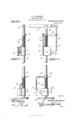
Figure 1 is a side elevation of a pipe lifting mechanism constructed in accordance with the invention; Fig. 2, a front elevation of same; Fig. 3, a section on the line 3-3 of Fig. 1; Fig. 4, a section on the line 44 of Fig. 1; and, Fig. 5, a detail perspective view of the supporting base of the mechanism.
Referring to the drawings, 10 indicates the base of the apparatus which is of circular formation and is provided with a radially disposed recess 11. Secured to and rising from the base 10 adjacent the inner end of the recess 11 is a. vertical bar 12, the upper end of which is forked, and between the arms of said forked end there is pivoted a lever 13. The holding clutch of the apparatus is indicated generally by A and comprises a head 14 which is fixedly secured to the bar 12 in proximity to the base 10. This head 14 is provided with a socket 15 in vertical alinement with the recess 11 of the base and which is adapted to receive a pipe 16 to be lifted. A pipe engaging arm 17 is pivotally connected to the head 14 and has its toothed engaging end 18 disposed within the socket 15 and adapted to engage the pipe 16 as same is elevated to hold it against movement back into the well. The
toothed end 18 of the arm 17 is so shaped and arranged however, that the pipe 16 is always free to move in an upward direction with respect to the interior of the well. Slidably mounted upon the bar 12 above the head 14 is a sleeve 19 which has projecting laterally therefrom a horizontal arm 20 which terminates in a vertical portion 21, and the free end of said vertical portion is pivotally connected with the end of the arm 17 which is disposed without the socket 15. A spring 22 encircles the bar 12 and has its upper end bearing against the sleeve 19 and its lower end against the head 14; said spring constantly tending to elevate the sleeve 19 and thereby raise the end of the arm 17 disposed without the socket 15 in an upward direction, whereby the engaging end 18 of said arm is forced against the pipe 16. From this construction it will be apparent that the pipe 16 can be elevated through the socket 15 without any hindrance to its movements being offered by the arm 17; however, it will also be apparent that any lowering of the pipe 16 will cause the engaging end of the arm 17 to bite and hold the pipe against movement in a downward direction.
The lifting clutch of the device is indicated generally by B and comprises a head 23 slidably mounted upon the bar 12 and provided with a pipe receiving socket 24 disposed in opposition to the socket 15 of the holding clutch, but in substantially the same vertical plane therewith. Pivotally connected to the head 23 is a pipe engaging arm 25 provided with a tooth engaging end 26 disposed within the socket 24. Rising from the upper end of the head 23 in parallel spaced relation to the bar 12 is a standard 27. A link 28 has one end pivotally connected to the lever 13 and its other end pivotally connected to the end of the arm 25 which is disposed without the socket 24. Slidably mounted upon the bar 12 and the upright 27 and having one end fixedly secured to the link 28 is an arm 29 and a spring 30 encircles the bar 12 and has its upper end in engagement with the arm 29 and its lower end with the head 23. As will be apparent, the spring 30 constantly tends to move the head 23 and the arm 29 away from each other, such movement causing the arm 25 to be swung on its pivot into position to engage and grip the pipe 16 when the clutch B is elevated through the medium of the lever 13.
It will be understood that in practice various changes in the form, proportion, size, and minor details in the construction may be resorted to without departing from the spirit or sacrificing any of the advantages of the invention.
What is claimed is:
1. A pipe lifting apparatus comprising a base having a vertical bar rising therefrom, a holding clutch mounted on said bar adjacent the base, and a lifting clutch disposed above the holding clutch; said lifting clutch comprising a head slidably mounted upon the bar and having a vertical. pipe receiving socket therein, a pipe engaging arm pivoted to the head and having its engaging end disposed within the socket, a lever pivoted to the upper end of said bar, and connections between the lever and the engaging arm whereby the movement of said lever in one direction Will simultaneously lift the head and force the engaging end of the arm against a pipe disposed within the socket.
2. A pipe lifting apparatus comprising a base having a vertical bar rising therefrom, a holding clutch mounted on said bar adjacent the base, and a lifting clutch disposed above the holding clutch; said lifting clutch comprising a head slidably mounted upon the bar and having a vertical pipe receiving socket therein, a standard rising from said head in parallel spaced relation to the bar, a pipe engaging arm pivoted to the head having its engaging end disposed within the socket, a lever pivoted to the upper end of said bar, a link connecting said lever and the end of the engaging arm disposed without the socket, an arm slidably engaging the upright rising from the head and the bar and having one end fixedly secured to said link, and a spring constantly tending to force said head away from the last named arm.
3. A pipe lifting apparatus comprising a base having a vertical bar rising therefrom, a holding clutch mounted on said bar adjacent the base; said holding clutch comprising a head fixed to 'the bar and having a vertical pipe receiving socket therein, a pipe engaging arm pivoted to the head and having its engaging end disposed within the socket, a sleeve slidably mounted upon said bar above the head, a connection between said sleeve and the end of the engaging arm without the socket for moving said arm into engagement with a pipe disposed within the socket when said sleeve is moved toward the upper end of the bar, and spring actuated means constantly tending to move said sleeve toward the upper end of the bar, a lifting.
clutch slidably mounted upon said bar, above the holding clutch, and means for sliding said lifting clutch upon the bar.
In testimony whereof, I affix my signature, in presence of two witnesses.
JACOB C. RONDEBUSH.
Vitnesses Mosns TETI-IERBY, WILLORD P. VANCE.
Copies of this patent may be obtained for five cents each, by addressing the Commissioner of Patents, Washington, D. C.
Priority Applications (1)
| Application Number | Priority Date | Filing Date | Title |
|---|---|---|---|
| US57512410A US990391A (en) | 1910-08-02 | 1910-08-02 | Well-pipe lifter. |
Applications Claiming Priority (1)
| Application Number | Priority Date | Filing Date | Title |
|---|---|---|---|
| US57512410A US990391A (en) | 1910-08-02 | 1910-08-02 | Well-pipe lifter. |
Publications (1)
| Publication Number | Publication Date |
|---|---|
| US990391A true US990391A (en) | 1911-04-25 |
Family
ID=3058728
Family Applications (1)
| Application Number | Title | Priority Date | Filing Date |
|---|---|---|---|
| US57512410A Expired - Lifetime US990391A (en) | 1910-08-02 | 1910-08-02 | Well-pipe lifter. |
Country Status (1)
| Country | Link |
|---|---|
| US (1) | US990391A (en) |
-
1910
- 1910-08-02 US US57512410A patent/US990391A/en not_active Expired - Lifetime
Similar Documents
| Publication | Publication Date | Title |
|---|---|---|
| US990391A (en) | Well-pipe lifter. | |
| US621790A (en) | williams | |
| US1043223A (en) | Pile-puller. | |
| US1018936A (en) | Pipe lifting and lowering jack. | |
| US2584801A (en) | Pipe extractor | |
| US1506581A (en) | Deep-well-casing clamp | |
| US611417A (en) | Sucker-rod lifter | |
| US487770A (en) | Lifting-jack | |
| US788738A (en) | Oil-well tube-clamp. | |
| US697625A (en) | Pipe-lifting mechanism. | |
| US1030084A (en) | Well-tubing safety appliance. | |
| US769943A (en) | Tamper. | |
| US543814A (en) | Carl a | |
| US826278A (en) | Lifting-jack. | |
| US742111A (en) | Pipe-jack. | |
| US1285102A (en) | Sucker-rod elevator. | |
| US1170813A (en) | Check-valve structure. | |
| US1017021A (en) | Windmill and engine coupling. | |
| US794912A (en) | Stump or rock extractor. | |
| US445900A (en) | Lifting-jack | |
| US1148366A (en) | Well-drilling apparatus. | |
| US254255A (en) | Lifting-jack | |
| US1631845A (en) | Sucker-rod elevator | |
| US1026536A (en) | Device for lifting tubes, tiles, and the like. | |
| US1005838A (en) | Supporting-hook. |