US9903742B2 - Displacement detecting device - Google Patents
Displacement detecting device Download PDFInfo
- Publication number
- US9903742B2 US9903742B2 US15/220,487 US201615220487A US9903742B2 US 9903742 B2 US9903742 B2 US 9903742B2 US 201615220487 A US201615220487 A US 201615220487A US 9903742 B2 US9903742 B2 US 9903742B2
- Authority
- US
- United States
- Prior art keywords
- light
- scale
- order
- index
- diffracted
- Prior art date
- Legal status (The legal status is an assumption and is not a legal conclusion. Google has not performed a legal analysis and makes no representation as to the accuracy of the status listed.)
- Active, expires
Links
Images


Classifications
-
- G—PHYSICS
- G01—MEASURING; TESTING
- G01D—MEASURING NOT SPECIALLY ADAPTED FOR A SPECIFIC VARIABLE; ARRANGEMENTS FOR MEASURING TWO OR MORE VARIABLES NOT COVERED IN A SINGLE OTHER SUBCLASS; TARIFF METERING APPARATUS; MEASURING OR TESTING NOT OTHERWISE PROVIDED FOR
- G01D5/00—Mechanical means for transferring the output of a sensing member; Means for converting the output of a sensing member to another variable where the form or nature of the sensing member does not constrain the means for converting; Transducers not specially adapted for a specific variable
- G01D5/26—Mechanical means for transferring the output of a sensing member; Means for converting the output of a sensing member to another variable where the form or nature of the sensing member does not constrain the means for converting; Transducers not specially adapted for a specific variable characterised by optical transfer means, i.e. using infrared, visible, or ultraviolet light
- G01D5/266—Mechanical means for transferring the output of a sensing member; Means for converting the output of a sensing member to another variable where the form or nature of the sensing member does not constrain the means for converting; Transducers not specially adapted for a specific variable characterised by optical transfer means, i.e. using infrared, visible, or ultraviolet light by interferometric means
-
- G—PHYSICS
- G01—MEASURING; TESTING
- G01D—MEASURING NOT SPECIALLY ADAPTED FOR A SPECIFIC VARIABLE; ARRANGEMENTS FOR MEASURING TWO OR MORE VARIABLES NOT COVERED IN A SINGLE OTHER SUBCLASS; TARIFF METERING APPARATUS; MEASURING OR TESTING NOT OTHERWISE PROVIDED FOR
- G01D5/00—Mechanical means for transferring the output of a sensing member; Means for converting the output of a sensing member to another variable where the form or nature of the sensing member does not constrain the means for converting; Transducers not specially adapted for a specific variable
- G01D5/26—Mechanical means for transferring the output of a sensing member; Means for converting the output of a sensing member to another variable where the form or nature of the sensing member does not constrain the means for converting; Transducers not specially adapted for a specific variable characterised by optical transfer means, i.e. using infrared, visible, or ultraviolet light
- G01D5/32—Mechanical means for transferring the output of a sensing member; Means for converting the output of a sensing member to another variable where the form or nature of the sensing member does not constrain the means for converting; Transducers not specially adapted for a specific variable characterised by optical transfer means, i.e. using infrared, visible, or ultraviolet light with attenuation or whole or partial obturation of beams of light
- G01D5/34—Mechanical means for transferring the output of a sensing member; Means for converting the output of a sensing member to another variable where the form or nature of the sensing member does not constrain the means for converting; Transducers not specially adapted for a specific variable characterised by optical transfer means, i.e. using infrared, visible, or ultraviolet light with attenuation or whole or partial obturation of beams of light the beams of light being detected by photocells
- G01D5/36—Forming the light into pulses
- G01D5/38—Forming the light into pulses by diffraction gratings
Definitions
- the present invention relates to a displacement detecting device, and more specifically, to a photoelectric encoder.
- a photoelectric encoder makes two beams diffracted by a scale diffraction grating interfere with each other, and obtains an interference signal. On the basis of this interference signal, the photoelectric encoder detects the relative displacement amount and relative displacement direction between the scale diffraction grating and a detecting head unit.
- the photoelectric encoder makes two diffracted lights interfere with each other. If only two diffracted lights interfere with each other, an ideal interference fringe (an interference signal) is obtained, so theoretical detection accuracy is supposed to be obtained. In many cases, as two diffracted lights which are made interfere with each other, for example, a positive first-order diffracted light and a negative first-order diffracted light are made interfere with each other.
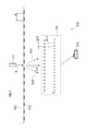
- FIG. 1 shows a displacement measuring device disclosed in Japanese Patent Application Publication No. 6-097171.
- Its optical system is composed mainly of a diffraction grating, and has a very simple structure.
- this displacement measuring device not only positive and negative first-order lights but also a zero-order light enters a photoelectric detector 18 .
- the grating height h of an index scale 14 is adjusted such that the phase difference between the positive or negative first-order light and the zero-order light which are generated by the index scale 14 becomes a predetermined phase (a phase difference ⁇ ).
- FIG. 3 shows a configuration example of an optical encoder proposed by the applicant of the present invention (Japanese Patent No. 4938926).
- a zero-order light is not a noise light, and is used as a signal light.
- two beams of the zero-order light and a first-order diffracted light interfere with each other.
- Patent Document 1 Japanese Patent Application Publication No. 6-097171
- Patent Document 2 Japanese Patent No. 4856844
- Patent Document 3 Japanese Patent No. 4938926
- the wavelength of light of the light source has varied.
- the diffraction angle (reflection angle) of the zero-order light does not vary.
- the diffraction angle of a first-order diffracted light varies. Then, the lengths of left and right light paths (the length of the light path of the zero-order light and the length of the light path of the first-order diffracted light) become asymmetrical, resulting in a difference between the light path lengths, whereby an interference signal (an interference fringe) is changed.
- Exemplary embodiments of the invention provide a high-accuracy photoelectric encoder, which obtains an interference signal by making two beams diffracted by a scale diffraction grating interfere with each other and has robustness to variation in the wavelength of light of a light source and contamination of the scale diffraction grating.
- a displacement detecting device comprising:
- a main scale including a diffraction grating
- a detecting head unit that is disposed so as to be relatively movable with respect to the main scale, and detects the amount of relative displacement to the main scale
- the detecting head unit includes:
- the displacement detecting device satisfies a first condition and a second condition
- N, m1, m2, u1, and u2 may be 2, 1, 2, 1, and 0, respectively.
- FIG. 1 is a view illustrating a displacement measuring device disclosed in Japanese Patent Application Publication No. 6-097171.
- FIG. 2 is a view illustrating a displacement measuring device disclosed in Japanese Patent No. 4856844.
- FIG. 3 is a view illustrating a displacement measuring device disclosed in Japanese Patent No. 4938926.
- FIG. 4 is a view for explaining the present invention.
- FIG. 5 is a view for explaining the present invention.
- FIG. 6 is a view for explaining the present invention.
- FIG. 7 is a view illustrating a first embodiment based on the present invention.
- FIG. 8 is a view illustrating the first embodiment based on the present invention.
- FIGS. 9A and 9B are views illustrating a related technology disclosed in Japanese Patent Application Laid-Open No. 8-219812, as a comparative example.
- FIG. 10 is a view illustrating the comparative example which is the related technology disclosed in Japanese Patent Application Laid-Open No. 8-219812.
- FIG. 6 is an enlarged view of a portion of FIG. 5 .
- a displacement detecting device 100 includes a main scale 110 , and a detecting head unit 130 which can relatively move with respect to the main scale 110 .
- the main scale 110 includes a diffraction grating 112 along the longitudinal direction of the main scale which is the length measurement axis direction.
- the diffraction grating is a transmission type.
- the diffraction grating may be a reflection type.
- the longitudinal direction (length measurement axis direction) of the main scale 110 is taken as an X axis
- the transverse direction of the main scale 110 is taken as a Y axis
- the direction of the normal to the main scale 110 is taken as a Z axis.
- the main scale 110 is, for example, a scale which is configured by depositing a thin metal film on a glass substrate.
- etching is performed, whereby the diffraction grating 112 having a grating pitch “g” is patterned.
- the method of forming the diffraction grating is not particularly limited.
- the diffraction grating 112 may be formed by forming ridges and grooves with a transparent resin on the glass substrate or by cutting some portions out of a non-transmissive member.
- the detecting head unit 130 includes a light source 131 , an index scale group 140 , and a light receiving unit 132 .
- the light source 131 is a light source for emitting a laser beam, and may be, for example, a laser diode (LD).
- the light source 131 emits light L along the Z axis, and the light L enters the main scale 110 at a right angle.
- the type of the light source is not limited.
- the light L is diffracted by the diffraction grating 112 of the main scale 110 .
- diffracted lights having various orders such as positive and negative first orders, positive and negative second orders, and positive and negative s-th orders are produced, and there is a zero-order light L 0 having passed through the diffraction grating without being diffracted.
- the index scale group 140 is composed of a plurality of (two or more) index scales, and the plurality of (two or more) index scales is arranged side by side at predetermined intervals.
- the index scale group 140 is positioned on the opposite side of the main scale 110 to the light source 131 .
- the index scales are given numbers 1, 2, 3, . . . , N ⁇ 1, and N, in order from the side near the main scale 110 .
- the grating pitches of the individual index scales are expressed as follow.
- the grating pitch P 0 of the main scale 110 the grating pitch P 1 of the first index scale, the grating pitch P 2 of the second index scale, the grating pitch P 3 of the third index scale, . . . , the grating pitch PN ⁇ 1 of the (N ⁇ 1)-th index scale, and the grating pitch PN of the N-th index scale are expressed as follow.
- the light receiving unit 132 is a photoelectric conversion element having a light receiving device.
- light paths from the light source 131 to the light receiving unit 132 are as shown in FIG. 5 .
- the light source light L from the light source 131 enters the main scale 110 at a right angle, whereby diffracted lights and a zero-order transmitted light are produced.
- the positive s-th order diffracted light Ls 1 of the diffracted lights from the main scale 110 enters the index scale group 140 . Then, the positive s-th order diffracted light Ls 1 is diffracted a plurality of times while passing through the individual index scales 1 to N.
- the positive s-th order diffracted light Ls 1 may pass through each of some of the index scales 1 to N, as a zero-order transmitted light, without being diffracted.
- an area in which the positive s-th order diffracted light Ls 1 is emitted from the index scale group 140 it is noted a light path along which the positive s-th order diffracted light Ls 1 enters the N-th index scale from the (N ⁇ 1)-th index scale, and is emitted from the N-th index scale, and reaches the light receiving unit 132 .
- an incidence angle at which the positive s-th order diffracted light Ls 1 enters the N-th index scale from the (N ⁇ 1)-th index scale is + ⁇ . Further, the positive s-th order diffracted light Ls 1 is diffracted by the N-th index scale (or passes through the N-th index scale), and is emitted from the N-th index scale.
- an emission angle at which the u1-th order light Lu 1 is emitted from the N-th index scale is + ⁇ 1 .
- the negative s-th order diffracted light Ls 2 is diffracted a plurality of times or passes through each of some index scales, as a zero-order transmitted light, without being diffracted.
- an area in which the negative s-th order diffracted light Ls 2 is emitted from the index scale group 140 it is noted a light path along which the negative s-th order diffracted light Ls 2 enters the N-th index scale from the (N ⁇ 1)-th index scale, and is emitted from the N-th index scale, and reaches the light receiving unit 132 .
- the light path of the positive s-th order diffracted light Ls 1 and the light path of the negative s-th order diffracted light Ls 2 should be symmetrical (that is, have the same light path length). Therefore, if the incidence angle at which the positive s-th order diffracted light Ls 1 enters the N-th index scale is + ⁇ , the incidence angle at which the negative s-th order diffracted light Ls 2 enters the N-th index scale is necessarily ⁇ .
- the negative s-th order diffracted light Ls 2 is diffracted by the N-th index scale (or passes through the N-th index scale), and is emitted from the N-th index scale. It is assumed that the negative s-th order diffracted light Ls 2 is diffracted by (or passing through) the N-th index scale, whereby multiple diffracted lights are produced, and the u2-th order light Lu 2 of those diffracted lights enters the light receiving unit 132 .
- an emission angle at which the u2-th order light Lu 2 is emitted from the N-th index scale is + ⁇ 2 .
- the zero-order light L 0 having passed through the main scale 110 enters the index scale group 140 , and is diffracted a plurality of times by or passes through the index scale group, and is emitted from the index scale group 140 .
- An incidence angle at which the zero-order light L 0 enters the N-th index scale is an alternate angle corresponding to the emission angle + ⁇ , and thus becomes ⁇ .
- the zero-order light L 0 is diffracted by the N-th index scale (or passes through the N-th index scale), and is emitted from the N-th index scale.
- the order of diffraction when the zero-order light L 0 having passed through the main scale 110 is diffracted by the i-th index scale of the index scale group 140 is represented by “ti” (wherein “ti” is an integer).
- the zero-order light LO from the main scale 110 is diffracted by (or passes through) the N-th index scale, thereby being split into a plurality of lights, which will be referred to collectively as the tN-th order light LtN.
- an emission angle at which the tN-th order light LtN is emitted from the N-th index scale is + ⁇ .
- the purpose of the present invention is to prevent the tN-th order light LtN from entering the light receiving unit 132 .
- the inventor of the present invention found that if an optical system is designed so as to satisfy the following two conditions, it is possible to secure high accuracy ad robustness in a photoelectric encoder 100 having the above described configuration.
- ⁇ is the wavelength of the light source light.
- ti represents the order of diffraction when the zero-order light L 0 having passed through the main scale 110 is diffracted by the i-th index scale of the index scale group 140 .
- the first condition is a condition which should be satisfied in order for the positive s-th order diffracted light Ls 1 and the negative s-th order diffracted light Ls 2 of the diffracted lights from the main scale 110 to be superimposed on each other and enter the light receiving unit 132 .
- ⁇ 1 should be equal to ⁇ 2 , that is, sin ⁇ 1 should be equal to sin ⁇ 2 .
- the zero-order light L 0 from the main scale 110 is diffracted by (or passes through) the N-th index scale, thereby being split into a plurality of lights, which will be referred to collectively as the tN-th order light LtN.
- the second condition expression is a condition expression which should be satisfied in order to prevent the tN-th order light LtN from entering the light receiving unit 132 .
- ti represents the order of diffraction when the zero-order light L 0 having passed through the main scale 110 is diffracted by the i-th index scale of the index scale group 140 , as described above.
- ⁇ should be different from ⁇ 1 , that is, sin ⁇ should be different from sin ⁇ 1 .
- condition that ⁇ should be different from ⁇ 1 is satisfied, on the basis of the first condition expression, the condition that ⁇ should be different from ⁇ 2 is automatically satisfied.
- the positive and negative s-th order lights Ls 1 and Ls 2 are used as signal lights, the light paths of the signal lights (the positive and negative s-th order lights Ls 1 and Ls 2 ) necessarily have a symmetrical structure. Therefore, it is possible to secure robustness to variation in the wavelength of light of the light source 131 .
- the beam diameter of the light source light L is set to an appropriate size, it is possible to suppress sensitivity (the rate of change of the amount of light) relative to contamination of the main scale 110 , and secure robustness to contamination of the main scale 110 .
- FIG. 7 shows a first embodiment based on the present embodiment.
- the grating pitch of the diffraction grating 112 of the main scale 110 is “g”.
- the index scale group 140 includes two index scales, that is, a first index scale and a second index scale.
- the grating pitches of the first index scale and the second index scale are “g/2”.
- a parameter “ ⁇ ” represents the wavelength of the light source light and is arbitrary.
- a parameter “g” represents the grating pitch of the main scale 110 , and is arbitrary.
- a parameter “N” represents the number of index scales constituting the index scale group 140 , and is 2.
- a parameter “m1” represents the ratio of the grating pitch of the main scale 110 to the grating pitch of the first index scale, and is 2.
- a parameter “m2” represents the ratio of the grating pitch of the main scale 110 to the grating pitch of the second index scale, and is 2.
- a parameter “s” represents the order of diffraction of each signal light, and is 1.
- a parameter “ ⁇ ” represents an angle at which each signal light enters the second index scale, and is sin ⁇ 1 ( ⁇ /g).
- a parameter “u1” represents the order of diffraction when one signal light (a positive first-order diffracted light Ls 1 ) is diffracted by the second index scale, and is 1.
- a parameter “u2” represents the order of diffraction when another signal light (a negative first-order diffracted light Ls2) is diffracted by the second index scale, and is 0.
- the left-hand side is equal to the right-hand side, and thus the first condition expression is satisfied.
- a portion of the positive first-order diffracted light emitted from the main scale 110 is diffracted by the second index scale, whereby a first-order diffracted light is produced, and this first-order diffracted light is extracted as one signal light.
- a portion of the negative first-order diffracted light from the main scale 110 passes through the second index scale, and this passed light (a zero-order light) is extracted as the other signal light.
- the location where the first-order diffracted light and the transmitted light (the zero-order light) finally reach is the light receiving unit 132 .
- the location of the light receiving unit 132 where the signal lights reach is necessarily different from the location where the zero-order light (transmitted light) from the main scale 110 reaches.
- the zero-order light from the main scale 110 enters the index scale group 140 , and is diffracted by or passes through the first index scale.
- the positive and negative first-order lights and the transmitted light (the zero-order light) from the first index scale are denoted by (0, +1), (0, ⁇ 1), and (0, 0), respectively.
- Each of these lights (0, +1), (0, ⁇ 1), and (0, 0) is diffracted by or passes through the second index scale.
- the light (0, 0) is diffracted by or passes through the second index scale, thereby being split into a plurality of lights such as lights (0, 0, +1), (0, 0, ⁇ 1), and (0, 0, 0); however, all of these lights do not reach the light receiving unit 132 .
- optical system is designed so as to satisfy the first condition expression and the second condition expression as described above, it is possible to separate the signal lights and the zero-order light.
- FIGS. 9A and 9B show a related technology disclosed in Japanese Patent Application Laid-Open No. 8-219812.
- the ratio of the grating pitch of the main scale 110 , the grating pitch of the first index scale, and the grating pitch of the second index scale is 1:1/2:1.
- the parameter “ ⁇ ” represents the wavelength of the light source light and is arbitrary.
- the parameter “g” represents the grating pitch of the main scale 110 , and is arbitrary.
- the parameter “N” represents the number of index scales constituting the index scale group 140 , and is 2.
- the parameter “m1” represents the ratio of the grating pitch of the main scale 110 to the grating pitch of the first index scale, and is 2.
- the parameter “m2” represents the ratio of the grating pitch of the main scale 110 to the grating pitch of the second index scale, and is 1.
- the parameter “s” represents the order of diffraction of each signal light, and is 1.
- the parameter “ ⁇ ” represents an angle at which each signal light enters the second index scale, and is sin ⁇ 1 ( ⁇ /g).
- the parameter “u1” represents the order of diffraction when one signal light (a positive first-order diffracted light Ls 1 ) is diffracted by the second index scale, and is 1.
- the parameter “u2” represents the order of diffraction when another signal light (a negative first-order diffracted light Ls 2 ) is diffracted by the second index scale, and is ⁇ 1.
- the left-hand side is equal to the right-hand side, and thus the first condition expression is satisfied.
- the left-hand side and the right-hand side can be equal to each other, so the zero-order light from the main scale 110 enters the light receiving unit 132 .
- the related technology in which the transmitted light (zero-order light) of the main scale 110 is mixed with the signal lights does not belong to the technical scope of the present invention.
- the present invention is valid.
Landscapes
- Physics & Mathematics (AREA)
- General Physics & Mathematics (AREA)
- Optical Transform (AREA)
- Diffracting Gratings Or Hologram Optical Elements (AREA)
Abstract
Description
-
- a light source that emits light toward the main scale;
- a light receiving unit that receives signal lights diffracted by the main scale, the signal lights being a positive s-th order diffracted light and a negative s-th order diffracted light of diffracted lights from the main scale, and
- an index scale group that is disposed in the middle of a light path from the main scale to the light receiving unit, the index scale group including two or more index scales including diffraction gratings, respectively, and
λ×(u1−u2)×(mN÷g)=2×sin α,
λ×u1×(mN÷g)−sin α≠λ÷g×Σ i=1 N(ti×mi).
λ×(u1−u2)×(mN÷g)=2×sin α (Expression 1)
λ×u1×(mN÷g)−sin α≠λ÷g×Σ i=1 N(ti×mi) (Expression 2)
sin α+sin β1=λ×u1×(mN÷g) (Expression 3)
sin(−α)+sin β2=λ×u2×(mN÷g) (Expression 4)
sin β1=λ×u1×(mN÷g)−sin α (Expression 5)
sin β2=λ×u2×(mN÷g)−sin(−α) (Expression 6)
λ×u1×(mN÷g)−sin α=λ×u2×(mN÷g)−sin(−α)
λ×(u1−u2)×(mN÷g)=2×sin α (Expression 1)
sin(−δ)+sin γ=λ×tN×(mN÷g) (Expression 7)
sin δ=+Σi=1 N-1 {ti×λ×(mi÷g)} (Expression 8)
sin γ=λ×tN×(mN÷g)−sin(−δ) (Expression 9)
sin γ=λ×tN×(mN÷g)+Σi=1 N-1 {ti×λ×(mi÷g)} (Expression 10)
sin γ=(λ÷g)×Σi=1 N(ti×mi) (Expression 11)
λ×u1×(mN÷g)−sin α≠(λ÷g)×Σi=1 N(ti×mi) (Expression 2)
Claims (2)
λ×(u1−u2)×(mN÷g)=2×sin α,
λ×u1×(mN÷g)−sin α≠λ÷g×Σ i=1 N(ti×mi),
Applications Claiming Priority (2)
| Application Number | Priority Date | Filing Date | Title |
|---|---|---|---|
| JP2015-148382 | 2015-07-28 | ||
| JP2015148382A JP6593868B2 (en) | 2015-07-28 | 2015-07-28 | Displacement detector |
Publications (2)
| Publication Number | Publication Date |
|---|---|
| US20170030745A1 US20170030745A1 (en) | 2017-02-02 |
| US9903742B2 true US9903742B2 (en) | 2018-02-27 |
Family
ID=56551307
Family Applications (1)
| Application Number | Title | Priority Date | Filing Date |
|---|---|---|---|
| US15/220,487 Active 2036-10-18 US9903742B2 (en) | 2015-07-28 | 2016-07-27 | Displacement detecting device |
Country Status (3)
| Country | Link |
|---|---|
| US (1) | US9903742B2 (en) |
| EP (1) | EP3124923B1 (en) |
| JP (1) | JP6593868B2 (en) |
Families Citing this family (6)
| Publication number | Priority date | Publication date | Assignee | Title |
|---|---|---|---|---|
| JP6705649B2 (en) * | 2015-12-22 | 2020-06-03 | 株式会社ミツトヨ | Encoder |
| JP6664211B2 (en) * | 2015-12-22 | 2020-03-13 | 株式会社ミツトヨ | Encoder |
| CN109011651B (en) * | 2018-07-25 | 2020-06-09 | 上海葡萄纬度科技有限公司 | Interactive toy |
| JP7319106B2 (en) | 2019-06-28 | 2023-08-01 | 株式会社ミツトヨ | Lattice part and its manufacturing method |
| JP7513510B2 (en) * | 2020-11-24 | 2024-07-09 | 株式会社ミツトヨ | Displacement sensor and shape measuring device |
| CN115437162B (en) * | 2022-08-19 | 2024-12-06 | 嘉兴驭光光电科技有限公司 | Laser projectors, camera assemblies and electronics |
Citations (9)
| Publication number | Priority date | Publication date | Assignee | Title |
|---|---|---|---|---|
| JPH0697171A (en) | 1992-09-11 | 1994-04-08 | Fujitsu Ltd | Method for manufacturing semiconductor device |
| JPH08219812A (en) | 1995-02-15 | 1996-08-30 | Canon Inc | Displacement information detection device, displacement information detection scale, and drive control device using the same |
| DE19716058A1 (en) | 1997-04-17 | 1998-10-22 | Heidenhain Gmbh Dr Johannes | Optical position measuring device |
| US20040090637A1 (en) | 2002-08-07 | 2004-05-13 | Wolfgang Holzapfel | Interferential position measuring arrangement |
| US20050140985A1 (en) | 2003-11-14 | 2005-06-30 | Mitutoyo Corporation | Apparatus for detecting displacement |
| US20070102630A1 (en) * | 2005-08-29 | 2007-05-10 | Canon Kabushiki Kaisha | Method and apparatus for measuring displacement |
| US20070267571A1 (en) | 2006-05-19 | 2007-11-22 | Nikon Corporation | Encoder |
| JP4938926B2 (en) | 2000-10-10 | 2012-05-23 | 株式会社ミツトヨ | Optical encoder |
| KR20130014184A (en) | 2011-07-29 | 2013-02-07 | 주식회사 져스텍 | Optical encoder |
Family Cites Families (5)
| Publication number | Priority date | Publication date | Assignee | Title |
|---|---|---|---|---|
| AT395914B (en) * | 1991-04-18 | 1993-04-26 | Rsf Elektronik Gmbh | PHOTOELECTRIC POSITION MEASURING DEVICE |
| JP3294684B2 (en) * | 1993-08-20 | 2002-06-24 | 株式会社ミツトヨ | Photoelectric encoder |
| JP2005016997A (en) * | 2003-06-24 | 2005-01-20 | Sankyo Seiki Mfg Co Ltd | Optical displacement detection device |
| DE102005029917A1 (en) * | 2005-06-28 | 2007-01-04 | Dr. Johannes Heidenhain Gmbh | Position measuring device |
| DE102005036180B4 (en) * | 2005-08-02 | 2020-08-27 | Dr. Johannes Heidenhain Gmbh | Optical position measuring device |
-
2015
- 2015-07-28 JP JP2015148382A patent/JP6593868B2/en active Active
-
2016
- 2016-07-27 US US15/220,487 patent/US9903742B2/en active Active
- 2016-07-28 EP EP16181609.5A patent/EP3124923B1/en active Active
Patent Citations (10)
| Publication number | Priority date | Publication date | Assignee | Title |
|---|---|---|---|---|
| JPH0697171A (en) | 1992-09-11 | 1994-04-08 | Fujitsu Ltd | Method for manufacturing semiconductor device |
| JPH08219812A (en) | 1995-02-15 | 1996-08-30 | Canon Inc | Displacement information detection device, displacement information detection scale, and drive control device using the same |
| DE19716058A1 (en) | 1997-04-17 | 1998-10-22 | Heidenhain Gmbh Dr Johannes | Optical position measuring device |
| JP4938926B2 (en) | 2000-10-10 | 2012-05-23 | 株式会社ミツトヨ | Optical encoder |
| US20040090637A1 (en) | 2002-08-07 | 2004-05-13 | Wolfgang Holzapfel | Interferential position measuring arrangement |
| JP4856844B2 (en) | 2002-08-07 | 2012-01-18 | ドクトル・ヨハネス・ハイデンハイン・ゲゼルシヤフト・ミツト・ベシユレンクテル・ハフツング | Interferometric position measuring device |
| US20050140985A1 (en) | 2003-11-14 | 2005-06-30 | Mitutoyo Corporation | Apparatus for detecting displacement |
| US20070102630A1 (en) * | 2005-08-29 | 2007-05-10 | Canon Kabushiki Kaisha | Method and apparatus for measuring displacement |
| US20070267571A1 (en) | 2006-05-19 | 2007-11-22 | Nikon Corporation | Encoder |
| KR20130014184A (en) | 2011-07-29 | 2013-02-07 | 주식회사 져스텍 | Optical encoder |
Non-Patent Citations (1)
| Title |
|---|
| European Search Report dated Dec. 7, 2016, 9 pages. |
Also Published As
| Publication number | Publication date |
|---|---|
| EP3124923B1 (en) | 2018-09-12 |
| JP6593868B2 (en) | 2019-10-23 |
| EP3124923A1 (en) | 2017-02-01 |
| JP2017026567A (en) | 2017-02-02 |
| US20170030745A1 (en) | 2017-02-02 |
Similar Documents
| Publication | Publication Date | Title |
|---|---|---|
| US9903742B2 (en) | Displacement detecting device | |
| US9383231B2 (en) | Photoelectric encoder having an interference pattern signal processing unit detects the pseudo-random data of the absolute pattern of an absolute scale | |
| US9395176B2 (en) | Optical position-measuring device | |
| US10082410B2 (en) | Optical position measuring device for generating wavelength-dependent scanning signals | |
| US10119802B2 (en) | Optical position-measuring device having grating fields with different step heights | |
| DE10308016B4 (en) | Displacement gauge with interference grid | |
| US10190892B2 (en) | Encoder | |
| US10831035B2 (en) | Optical encoder | |
| US10393585B2 (en) | Spectral detector and spectral detecting method using the same | |
| US8772706B2 (en) | Multiple wavelength configuration for an optical encoder readhead including dual optical path region with an optical path length difference | |
| US10190893B2 (en) | Encoder | |
| JP4506271B2 (en) | Photoelectric encoder | |
| US11353583B2 (en) | Optical position-measurement device with varying focal length along a transverse direction | |
| US10591321B2 (en) | Optical encoder | |
| JP5154072B2 (en) | Photoelectric encoder | |
| US20240110816A1 (en) | Optical encoder | |
| US11506518B2 (en) | Photoelectric rotary encoder | |
| US10746573B2 (en) | Optical encoder and measurement device including the same | |
| JP2019215170A (en) | Optical unit and displacement measurement device | |
| JPS5939683B2 (en) | Optical displacement detection method | |
| JP5980028B2 (en) | Light receiving element for photoelectric encoder and photoelectric encoder | |
| JP2005083808A (en) | Optical origin detection sensor, its origin detection method, and optical encoder | |
| JP3429961B2 (en) | Optical encoder | |
| JP2006284421A (en) | Encoder | |
| JP2018091769A (en) | Displacement detector |
Legal Events
| Date | Code | Title | Description |
|---|---|---|---|
| AS | Assignment |
Owner name: MITUTOYO CORPORATION, JAPAN Free format text: ASSIGNMENT OF ASSIGNORS INTEREST;ASSIGNOR:KIMURA, AKIHIDE;REEL/FRAME:039274/0276 Effective date: 20160412 |
|
| STCF | Information on status: patent grant |
Free format text: PATENTED CASE |
|
| MAFP | Maintenance fee payment |
Free format text: PAYMENT OF MAINTENANCE FEE, 4TH YEAR, LARGE ENTITY (ORIGINAL EVENT CODE: M1551); ENTITY STATUS OF PATENT OWNER: LARGE ENTITY Year of fee payment: 4 |
|
| MAFP | Maintenance fee payment |
Free format text: PAYMENT OF MAINTENANCE FEE, 8TH YEAR, LARGE ENTITY (ORIGINAL EVENT CODE: M1552); ENTITY STATUS OF PATENT OWNER: LARGE ENTITY Year of fee payment: 8 |