US9897813B2 - Ocular vision system with optical guide that can be positioned in two positions - Google Patents
Ocular vision system with optical guide that can be positioned in two positions Download PDFInfo
- Publication number
- US9897813B2 US9897813B2 US14/894,608 US201414894608A US9897813B2 US 9897813 B2 US9897813 B2 US 9897813B2 US 201414894608 A US201414894608 A US 201414894608A US 9897813 B2 US9897813 B2 US 9897813B2
- Authority
- US
- United States
- Prior art keywords
- optical guide
- vision system
- ocular vision
- user
- eye
- Prior art date
- Legal status (The legal status is an assumption and is not a legal conclusion. Google has not performed a legal analysis and makes no representation as to the accuracy of the status listed.)
- Expired - Fee Related
Links
Images


Classifications
-
- G—PHYSICS
- G02—OPTICS
- G02B—OPTICAL ELEMENTS, SYSTEMS OR APPARATUS
- G02B27/00—Optical systems or apparatus not provided for by any of the groups G02B1/00 - G02B26/00, G02B30/00
- G02B27/01—Head-up displays
- G02B27/0179—Display position adjusting means not related to the information to be displayed
-
- G—PHYSICS
- G02—OPTICS
- G02B—OPTICAL ELEMENTS, SYSTEMS OR APPARATUS
- G02B27/00—Optical systems or apparatus not provided for by any of the groups G02B1/00 - G02B26/00, G02B30/00
- G02B27/01—Head-up displays
- G02B27/017—Head mounted
- G02B27/0172—Head mounted characterised by optical features
-
- G—PHYSICS
- G02—OPTICS
- G02B—OPTICAL ELEMENTS, SYSTEMS OR APPARATUS
- G02B27/00—Optical systems or apparatus not provided for by any of the groups G02B1/00 - G02B26/00, G02B30/00
- G02B27/01—Head-up displays
- G02B27/017—Head mounted
- G02B27/0176—Head mounted characterised by mechanical features
-
- G—PHYSICS
- G02—OPTICS
- G02C—SPECTACLES; SUNGLASSES OR GOGGLES INSOFAR AS THEY HAVE THE SAME FEATURES AS SPECTACLES; CONTACT LENSES
- G02C11/00—Non-optical adjuncts; Attachment thereof
- G02C11/10—Electronic devices other than hearing aids
-
- G—PHYSICS
- G02—OPTICS
- G02C—SPECTACLES; SUNGLASSES OR GOGGLES INSOFAR AS THEY HAVE THE SAME FEATURES AS SPECTACLES; CONTACT LENSES
- G02C5/00—Constructions of non-optical parts
- G02C5/12—Nose pads; Nose-engaging surfaces of bridges or rims
- G02C5/122—Nose pads; Nose-engaging surfaces of bridges or rims with adjustable means
- G02C5/124—Nose pads; Nose-engaging surfaces of bridges or rims with adjustable means for vertically varying the position of the lenses
-
- G—PHYSICS
- G06—COMPUTING OR CALCULATING; COUNTING
- G06F—ELECTRIC DIGITAL DATA PROCESSING
- G06F3/00—Input arrangements for transferring data to be processed into a form capable of being handled by the computer; Output arrangements for transferring data from processing unit to output unit, e.g. interface arrangements
- G06F3/01—Input arrangements or combined input and output arrangements for interaction between user and computer
- G06F3/017—Gesture based interaction, e.g. based on a set of recognized hand gestures
-
- G—PHYSICS
- G06—COMPUTING OR CALCULATING; COUNTING
- G06T—IMAGE DATA PROCESSING OR GENERATION, IN GENERAL
- G06T19/00—Manipulating three-dimensional [3D] models or images for computer graphics
- G06T19/006—Mixed reality
-
- H—ELECTRICITY
- H04—ELECTRIC COMMUNICATION TECHNIQUE
- H04N—PICTORIAL COMMUNICATION, e.g. TELEVISION
- H04N23/00—Cameras or camera modules comprising electronic image sensors; Control thereof
- H04N23/50—Constructional details
- H04N23/54—Mounting of pick-up tubes, electronic image sensors, deviation or focusing coils
-
- H04N5/2253—
-
- G—PHYSICS
- G02—OPTICS
- G02B—OPTICAL ELEMENTS, SYSTEMS OR APPARATUS
- G02B27/00—Optical systems or apparatus not provided for by any of the groups G02B1/00 - G02B26/00, G02B30/00
- G02B27/01—Head-up displays
- G02B27/0101—Head-up displays characterised by optical features
- G02B2027/0138—Head-up displays characterised by optical features comprising image capture systems, e.g. camera
-
- G—PHYSICS
- G02—OPTICS
- G02B—OPTICAL ELEMENTS, SYSTEMS OR APPARATUS
- G02B27/00—Optical systems or apparatus not provided for by any of the groups G02B1/00 - G02B26/00, G02B30/00
- G02B27/01—Head-up displays
- G02B27/0149—Head-up displays characterised by mechanical features
- G02B2027/0154—Head-up displays characterised by mechanical features with movable elements
- G02B2027/0158—Head-up displays characterised by mechanical features with movable elements with adjustable nose pad
-
- G—PHYSICS
- G02—OPTICS
- G02B—OPTICAL ELEMENTS, SYSTEMS OR APPARATUS
- G02B27/00—Optical systems or apparatus not provided for by any of the groups G02B1/00 - G02B26/00, G02B30/00
- G02B27/01—Head-up displays
- G02B27/0149—Head-up displays characterised by mechanical features
- G02B2027/0154—Head-up displays characterised by mechanical features with movable elements
- G02B2027/0159—Head-up displays characterised by mechanical features with movable elements with mechanical means other than scaning means for positioning the whole image
-
- G—PHYSICS
- G02—OPTICS
- G02B—OPTICAL ELEMENTS, SYSTEMS OR APPARATUS
- G02B27/00—Optical systems or apparatus not provided for by any of the groups G02B1/00 - G02B26/00, G02B30/00
- G02B27/01—Head-up displays
- G02B27/017—Head mounted
- G02B2027/0178—Eyeglass type
Definitions
- the present invention relates to the field of ocular vision systems based on optical guides. Such optical guides enable an image to be transported without deformation and thus enable superimposing this transported image on an external scene perceived by the eye of the user of the ocular vision system.
- the present invention also relates to the field of such ocular vision systems further equipped with an image capture device.
- An optical guide generally comprises an injection system, thanks to which the light beam transporting an image is introduced.
- the light beam transporting the image issues from a source that may be a matrix of pixels of the LCD (liquid crystal display) or LCOS (liquid crystal on silicon) type illuminated by a light source, or of the OLED (organic light-emitting diode) type.
- the light beam next passes through an optical system for obtaining a collimated beam, meaning wherein the rays are substantially parallel. It is also said that the image is thus borne to infinity.
- the collimated beam is then introduced into the injection section of the optical guide.
- the optical guide enables the light beam to propagate by total internal reflections, optionally thanks to a specific treatment of the walls of the optical guide.
- the light beam thus propagates are far as an extraction section for the light beam to emerge from the optical guide.
- the extraction section may consist of a reflector terminating the optical guide in an inclined plane.
- the patent FR 2 925 172 B1 describes an optical guide provided with an extraction section consisting of reflective microstructures formed on the surface of the optical guide. These microstructures consist of prisms having an angle enabling the light beam to emerge from the optical guide.
- the microstructures are spaced apart by interstitial spaces formed in line with the surface of the optical guide. These interstitial spaces, meaning not covered with microstructures and fitting between the latter, are transparent and thus enable obtaining the see-through effect. This allows seeing the image transported by the light beam as well as the scenes beyond the optical guide.
- These interstitial spaces do however imply a phenomenon of variation of luminance on the transparency of the optical guide, which causes interferences on the vision of the surrounding scenes through the optical guide.
- Such optical guides are for example used in ocular vision systems.
- the transported image must then be in the nominal axis of sight of the eye of the user.
- Nominal axis of sight of the eye means the axis passing through the centre of the eye and through the centre of the pupil of the eye when the user is looking straight in front of him (meaning the nominal axis of sight of the eye is the horizontal when the user is holding his head straight).
- the ocular vision system may be equipped with an image capture device, such as a video camera or a photographic apparatus.
- an image capture device such as a video camera or a photographic apparatus.
- the invention concerns an ocular vision system intended to be worn by a user, said system comprising a display module, the display module comprising a transparent optical guide adapted for propagating, by total internal reflections, a light beam transporting an image for an extraction section of said optical guide.
- Said system comprises: means for positioning the optical guide in a first position in which the extraction zone is placed along a first axis corresponding to a nominal axis of sight of the eye of the user; means for positioning the optical guide in a second position in which the extraction zone is placed along a second axis offset with respect to the nominal axis of sight of the eye of the user; and means for rotating the optical guide about an axis intended to pass substantially through the centre of rotation of the eye of the user, adapted for enabling the optical guide to pass from the first position to the second position and vice versa.
- the ocular vision system may comprise means for positioning the optical guide in more than two positions by rotation about an axis passing substantially through the centre of the eye, each enabling the user to view the image transported by the optical guide.
- the second axis is offset by 20° with respect to the nominal axis of sight of the eye of the user.
- the nominal axis of sight of the eye of the user can be left clear from the presence of the optical guide while keeping a suitable eye box.
- said system being spectacles
- the display module being fixed to one of the sidepieces of said spectacles
- said system further comprises means for adjusting a nose pad of said spectacles for height.
- said height-adjustment means comprise a knurled wheel and means for converting a rotation movement of the knurled wheel into a translation movement of the nose pad.
- the adjustment for height can be carried out finely.
- said height-adjustment means comprise a rack composed of notches, each of the notches defining a predefined height of the nose pad.
- said system being spectacles
- the display module being fixed to one of the sidepieces of said spectacles
- said system further comprises a battery fixed to the other sidepiece of said spectacles.
- said system in order to rotate the optical guide between the first position and the second position about a rotation axis intended to pass substantially through the centre of rotation of the eye of the user, said system comprises: a stud holder that comprising at least one stud; a fixing and guiding support comprising at least one oblong groove intended to receive said stud, each groove being such that, when said stud is placed at one end of said groove, the optical guide is in the first position and when said stud is placed at the other end of said groove the optical guide is in the second position; and a spring for providing engagement of each stud in a said corresponding oblong groove.
- each oblong groove comprises at each of its ends a blind hole adapted for receiving one said corresponding stud under the action of said spring.
- said system further comprises an operating button fixed to the stud holder and adapted for countering the action of the spring in order to disengage each stud from the corresponding oblong groove.
- said system comprises a housing in which a recess is formed, the recess being intended to receive the stud holder and the fixing and guiding support, the mouth of the opening comprising, at one point, a larger part to enable inserting the stud holder and the spring in said housing.
- an image capture device is mounted securely on the display module so that the axis of sight of said image capture device is parallel to the axis of sight of the user when the user is looking through the optical guide.
- the axis of sight of the image capture device makes a rotation at the same time and of the same magnitude as the optical guide. Then, when the user is facing a person, placing the optical guide in the second position means that the images of the person can no longer be taken, which minimises privacy issues.
- said system comprises at least one position sensor for detecting when the optical guide is in the first position and/or when the optical guide is in the second position.
- said system comprises at least one indicator light associated with said position sensor or sensors, a first state of which represents the optical guide in the first position and a second state of which represents the optical guide in the second position.
- said system comprises communication means adapted for transmitting to a server images captured with said image capture device and information representing the position of the optical guide detected by said sensor or sensors and for receiving from the server the image to be transported by the optical guide.
- the server can apply different processing operations to the received images, depending on the position in which the optical guide is situated (and consequently according to the position in which the image capture device is situated).
- said image capture device being a video camera
- said server is adapted for: applying processing for applying augmented reality to the images received from the ocular vision system, when the optical guide is in the first position; and applying processing for applying gesture recognition to the images received from the ocular vision system, when the optical guide is in the second position.
- said system comprises supplementary rotation means adapted for enabling, when the optical guide is in the first position, adjusting the extraction zone horizontally with respect to the nominal axis of sight of the eye of the user.
- said system can easily adapt to bending tolerances of a spectacle frame on which said system is mounted and/or dimension tolerances of said frame and/or a greater variety of inter-pupil distances.
- FIG. 1 schematically illustrates an optical guide as used in at least one embodiment of the present invention
- FIG. 2A schematically illustrates an ocular vision system in which the optical guide is placed in a first position
- FIG. 2B schematically illustrates the optical vision system in which the optical guide is placed in a second position
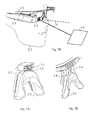
- FIG. 3A schematically illustrates a mechanism for adjusting a spectacle nose pad for height, in a particular embodiment of the ocular vision system
- FIG. 3B schematically illustrates another mechanism for adjusting the spectacle nose pad for height in a particular embodiment of the ocular vision system
- FIG. 4A schematically illustrates a first exploded view of a rotation mechanism of the ocular vision system, enabling the optical guide to pass from the first position to the second position and vice versa, in a particular embodiment of the ocular vision system;
- FIG. 4B schematically illustrates a second exploded view of a rotation mechanism of the ocular vision system, enabling the optical guide to pass from the first position to the second position and vice versa, in a particular embodiment of the ocular vision system;
- FIG. 5A schematically illustrates a first view of a spectacle sidepiece housing, for using the rotation mechanism of the ocular vision system, in a particular embodiment of the ocular vision system;
- FIG. 5B schematically illustrates a second view of a spectacle sidepiece housing, for using the rotation mechanism of the ocular vision system, in a particular embodiment of the ocular vision system;
- FIG. 6 schematically illustrates a fixing and guiding support forming part of the rotation mechanism of the ocular vision system in a particular embodiment of the ocular vision system
- FIG. 7A schematically illustrates a first arrangement of an eye box in the first position
- FIG. 7B schematically illustrates a second arrangement of an eye box in the second position
- FIG. 7C schematically illustrates a third eye box arrangement
- FIG. 8 schematically illustrates another ocular vision system that is equipped with an image capture device
- FIG. 9A schematically illustrates said other ocular vision system in which the optical guide is placed in the first position and the image capture device is placed in a corresponding position;
- FIG. 9B schematically illustrates said other ocular vision system in which the optical guide is placed in the second position and the image capture device is placed in another corresponding position;
- FIG. 10A schematically illustrates a fourth eye box arrangement
- FIG. 10B schematically illustrates a fifth eye box arrangement.
- the present invention consists of an ocular vision system comprising an optical guide for transporting an image without deformation and thus enabling superimposing this transported image on an external scene perceived by the eye of a user of the ocular vision system.
- the ocular vision system is a pair of informative spectacles.
- the invention may however be implemented in another context, such as for example a pilot helmet or any other equipment intended to be worn fixedly with respect to the head of the user.
- the ocular system may be an audio headset on which the optical guide is rotatably mounted.
- FIG. 1 schematically illustrates an optical guide as may be used in the ocular vision system.
- the optical guide is based on the one described in the international patent application WO 2012/136470 A1, and comprises two main parts: a first part 1 . 5 and a second part 1 . 10 .
- the first part 1 . 5 enables a light beam 1 . 6 transporting an image (a video being a succession of images at a predefined rate) to propagate, by successive reflections, over a predefined distance.
- the first part 1 . 5 comprises an extraction section for bringing the light beam out of the optical guide once the beam has reached this predefined distance.
- the second part 1 . 10 consists of a material substantially identical to that of said first part 1 . 5 .
- the second part 1 . 10 is superimposed on the first part 1 . 5 and enables obtaining the see-through effect without any phenomenon of variation in luminance on the transparency of the optical guide.
- a light source 1 . 1 generates the light beam transporting the image intended to pass through the optical guide.
- This source may consist of a matrix of LCD or LCOS pixels having backlighting or a matrix of OLED pixels.
- the light beam is then collimated by an optical system 1 . 2 .
- the various pixels of the image are therefore projected by a beam of parallel light rays 1 . 3 emerging from the optical system 1 . 2 , and the field of vision is defined by the focal length of the lens and by the half-diagonal of the image to be transported.
- the collimated light beam 1 . 3 is then projected into an injection section 1 . 4 to enable the light beam to be propagated by total internal reflections in the optical guide.
- the light beam is then transported in the first part 1 . 5 until it reaches the extraction section, from which the light beam is projected out of the optical guide.
- the first part 1 . 5 consists of a material transparent to light. If the refractive index of the material is higher than the refractive indices of the media that surround it, total internal reflections occur naturally provided that the angle of incidence of the rays of the beam, with respect to the surface on which the light beam strikes, is sufficiently small.
- the extraction section is situated on one of the faces of the first part 1 . 5 .
- the extraction section makes it possible to return the light beam towards the other face of the first part 1 . 5 at a substantially perpendicular angle, which enables the light beam 1 . 8 to leave the optical guide.
- the light beam 1 . 8 is thus projected out of the guidance device towards the eye of the user of the ocular vision system.
- the extraction section is situated in a zone 1 . 7 of the optical guide, in which the first part 1 . 5 comprises at least one microstructure, situated on the surface and comprising a flat surface suitable for enabling the rays of the light beam that come to strike said flat surface to emerge from the optical guide.
- the second part 1 . 10 comprises at least one microstructure with a form complementary to that or those of the first part 1 . 5 .
- the microstructures that are complementary to each other are thus placed facing each other.
- the first 1 . 5 and second 1 . 10 parts are assembled so that any microstructure of the extraction section is separated from its complementary microstructure by a transparent medium of substantially constant thickness.
- the thickness is chosen so as to imply a limited modification of the vision of the external scene.
- the microstructures and their complements being substantially parallel because of the substantially constant thickness of the transparent medium, the vision of the external scene is not substantially modified since the rays undergo only a small translation.
- Eye box means the space in which the collimated image is formed, transported by the optical guide, intended to be seen by the user.
- eye box the length of which is around 9 mm and the height of which is around 5 mm.
- a typical diameter of a pupil of a human eye being around 3 to 4 mm, such an eye box enables various users with various inter-pupil distances to use the ocular vision system without having to make a horizontal adjustment of the positioning of the eye box.
- FIG. 2A schematically illustrates an ocular vision system in which the optical guide is placed in a first position.
- the ocular vision system is constructed on the basis of spectacles 2 . 3 intended to be worn by a user, whose head 2 . 2 is also schematically depicted in FIG. 2A .
- the spectacles 2 . 3 may be equipped with transparent, tinted or photochromic lenses.
- the ocular vision system comprises a display module 2 . 1 .
- the display module 2 . 1 comprises an optical guide 2 . 4 , as previously described in relation to FIG. 1 .
- the display module 2 . 1 and consequently the optical guide 2 . 4 , is thus rotatably mounted on the spectacles 2 . 3 .
- the display module 2 . 1 is for example mounted, as illustrated in FIG. 2A , on the right-hand sidepiece of the spectacles 2 . 3 .
- a symmetrical arrangement would enable installing the display module 2 . 1 on the left-hand sidepiece.
- the display module 2 . 1 is power-supplied thanks to a battery mounted on the other sidepiece of the spectacles 2 . 3 , which allows distributing the weight of the ocular vision system and thus to provide better stability of the spectacles 2 . 3 when used and therefore better comfort for the user.
- the first position of the optical guide 2 . 4 is such that the extraction zone of the optical guide 2 . 4 is substantially centred on the nominal axis of sight of the eye of the user.
- An optical mechanism for adjusting a nose pad 2 . 5 of the spectacles 2 . 3 for height, enabling adjusting the vertical position of the eye box with respect to the nominal axis of sight of the eye of the user, is described below in relation to FIG. 3A .
- An alternative optional mechanism for adjusting the nose pad 2 . 5 for height, enabling adjusting the vertical positioning of the eye box with respect to the nominal axis of sight of the eye of the user, is described below in relation to FIG. 3B .
- An optional mechanism for adjusting horizontally the optical guide 2 . 4 enabling adjusting the horizontal positioning of the eye box with respect to the nominal axis of sight of the eye of the user, is described below in relation to FIGS. 10A and 10B .
- the first position depicted in FIG. 2A enables creating an eye box intended to completely encompass the pupil of the user.
- a representation of this eye box is provided in FIG. 7A , described below.
- the first position depicted in FIG. 2A thus enables the user to see, in a superimposed fashion, the external scene in a see-through manner and an image 2 . 6 transported by the optical guide 2 . 4 .
- This first position is particularly suited to an augmented reality application, by the superimposition of virtual images (transported by the optical guide 2 . 4 ) on the real images (seen through the optical guide 2 . 4 ).
- FIG. 2B schematically illustrates the ocular vision system of FIG. 2A , but in which the optical guide 2 . 4 . is placed in a second position.
- the display module 2 . 1 is rotatably mounted, as in FIG. 2A , on the right-hand sidepiece of the spectacles 2 . 3 .
- the second position of the optical guide 2 . 4 is such that the extraction zone of the optical guide 2 . 4 is offset by a predefined angle ⁇ with respect to the nominal axis of sight of the eye of the user, taking as the rotation axis an axis passing substantially through the centre of rotation of the eye, i.e. the centre of the eye.
- the rotation takes place so that the optical guide 2 . 4 in the first position is aligned vertically with the optical guide 2 . 4 in the second position.
- the aforementioned rotation axis is horizontal and perpendicular to the nominal axis of sight of the eye.
- the rotation takes place so that the optical guide 2 . 4 in the first position is aligned horizontally with the optical guide 2 . 4 in the second position. In other words, the aforementioned rotation is then vertical.
- the angle ⁇ is preferentially 20° so as to leave clear the nominal axis of sight of the eye from the presence of the optical guide 2 . 4 .
- the second position is also preferentially lower than the first position. This is because looking towards the ground is more comfortable for the eye than looking upwards, and the luminosity is there typically more suitable for looking at the image transported by the optical guide 2 . 4 .
- a vertical movement of the optical guide 2 . 4 affords a smaller space requirement than the horizontal movement of the optical guide 2 . 4 .
- the second position depicted in FIG. 2B enables creating an eye box intended to completely encompass the pupil of the user when the user offsets his axis of sight by the angle ⁇ downwards without moving his head.
- a representation of this eye box is provided in FIG. 2B , described below.
- the second position depicted in FIG. 2B thus enables the user to see, by lowering his eyes, the image 2 . 6 transported by the optical guide 2 . 4 .
- This second position is particularly suited to an application of the dashboard type.
- the passage from the first position to the second position of the optical guide 2 . 4 takes place by rotation of the display module 2 . 1 with respect to the spectacles frame. This rotation takes place with respect to a rotation axis passing substantially through the centre of rotation of the eye of the user.
- a preferential mechanism enabling fixing the display module 2 . 1 to the spectacles 2 . 3 and also enabling performing this rotation is described below in relation to FIGS. 4A, 4B, 5A, 5B and 6 .
- FIGS. 2A and 2B focus on the positioning of the optical guide 2 . 4 with respect to the spectacles frame.
- the ocular vision system may further comprise an image capture device, such as a video camera or a photographic apparatus. This aspect is described below in relation to FIGS. 8, 9A and 9B .
- FIG. 3A schematically illustrates a mechanism for adjusting a nose pad 2 . 5 of the spectacles 2 . 3 for height.
- the user can ensure that his/her pupil fits in the eye box created in the first position of the optical guide, and consequently in the second position of the optical guide 2 . 4 .
- the user places the display module 2 . 1 so that the optical guide 2 . 4 is placed in the first position.
- the user then adjusts the height of the nose pad 2 . 5 with respect to the frame of the spectacles 2 . 3 until the image transported by the optical guide 2 . 4 is completely visible to the eye of the user.
- the user makes the vertical adjustment of the eye box.
- this adjustment remains applicable for the second position of the optical guide 2 . 4 .
- This ease of adjustment stems from the fact that the rotation for passing from the first position of the optical guide 2 . 4 to the second position of the optical guide 2 . 4 , and vice versa, takes place around a rotation axis passing substantially through the centre of rotation of the eye of the user.
- a further adjustment of the eye box would be necessary in the second position of the optical guide 2 . 4 if the rotation axis had been different, in particular if the rotation axis passed substantially through the focal centre of the eye.
- the nose pad 2 . 5 is assembled with the frame of the spectacles 2 . 3 thanks to translational adjustment means 3 . 2 to enable the nose pad 2 . 5 to be adjusted for height.
- the translational adjustment means 3 . 2 preferentially comprise a knurled wheel 3 . 1 affording a fine adjustment of the height of the nose pad 2 . 5 .
- the conversion of the rotation movement of the knurled wheel 3 . 1 into a translation movement of the nose pad 2 . 5 is for example achieved thanks to an assembly formed by a threaded rod, rotated by the knurled wheel 3 . 1 , and a tapped hole formed in the nose pad 2 . 5 .
- the fineness of the adjustment of the nose pad 2 is for example achieved thanks to an assembly formed by a threaded rod, rotated by the knurled wheel 3 . 1 , and a tapped hole formed in the nose pad 2 . 5 .
- translational adjustment means 3 . 2 may be supplemented by translational guidance and rotational locking means 3 . 2 thus providing effective translation of the nose pad 2 . 5 by rotation of the knurled wheel 3 . 1 .
- Such guidance means 3 . 2 for example take the form of blades inserted in slots in the nose pad 2 . 5 .
- FIG. 3B Another example embodiment is shown in FIG. 3B .
- FIG. 3B schematically illustrates a mechanism for adjusting the height of the nose pad 2 . 5 .
- the user can ensure that his pupil fits in the eye box created in the first position of the optical guide, and consequently in the second position of the optical guide 2 . 4 .
- the nose pad 2 . 5 is assembled with the spectacle frame 2 . 3 thanks to translational adjustment means 3 . 4 to enable the adjustment of the height of the nose pad 2 . 5 .
- the translational adjustment means 3 . 4 preferentially include a rack 3 . 5 comprising notches, each of these notches enabling placing the nose pad 2 . 5 at a predefined height relative to the frame of the spectacles 2 . 3 .
- the fineness of the adjustment of the nose pad 2 . 5 for height then depends on the size of the notches on the rack 3 . 5 .
- the part of the nose pad 2 . 5 that is intended to be in abutment on the nose of the user is made from a supple material, optionally flexible, to properly match the shape of the nose.
- FIGS. 4A and 4B schematically illustrate a first exploded view, and respectively a second exploded view, of a rotation mechanism of the ocular vision system, enabling the optical guide 2 . 4 to pass from the first position to the second position, and vice versa.
- FIGS. 4A and 4B comprise schematically and partially a sidepiece 4 . 1 of the spectacles 2 . 3 , on which the display module is intended to be fixed, and this in a way that is easily removable without having recourse to tools.
- the sidepiece 4 . 1 is provided with a housing 4 . 2 comprising a recess 4 . 7 in which a stud holder 4 . 4 and a fixing and guiding support 4 . 5 are intended to be housed.
- a perspective view of the fixing and guiding support 4 . 5 is shown in FIG. 6 .
- a perspective view of the housing 4 . 2 is shown in FIG. 5A .
- the recess 4 . 7 emerges on an anterior wall of the housing 4 . 2 as shown in FIG. 5B .
- a wall of the housing 4 . 2 has been disconnected from the rest of the housing 4 . 2 in order to facilitate identification of the parts of the rotation mechanism.
- the stud holder 4 . 4 is secured to the sidepiece 4 . 1 thanks to a spring 4 . 3 .
- the spring 4 . 3 bears for example in a first blind hole formed in the first block 4 . 2 and bears on the stud holder 4 . 4 thanks to a second blind hole formed in the stud holder 4 . 4 or by virtue of a shoulder in a through hole formed in the stud holder 4 . 4 .
- the spring 4 . 3 is such that, at rest, the spring 4 . 3 tends to press the stud holder 4 . 4 on the fixing and guiding support 4 . 5 .
- the fixing and guiding support 4 . 5 is fixed to the display module 2 . 1 , or forms part of the display module 2 . 1 .
- the fixing and guiding support 4 . 5 interacts with the stud holder 4 . 4 to enable the display module 2 . 1 to be rotated with respect to the frame of the spectacles 2 . 3 and thus to enable the optical guide 2 . 4 to pass from the first position to the second position and vice versa.
- the stud holder 4 . 4 comprises at least one stud 4 . 9 .
- the stud holder 4 . 4 comprises, in an illustrative fashion, two studs 4 . 9 . Each stud 4 .
- Each oblong groove 6 . 1 is such that, when the stud 4 . 9 that corresponds thereto is positioned at one end of said oblong groove 6 . 1 , the optical guide is placed in the first position and, when said stud 4 . 9 is positioned at the other end of said oblong groove 6 . 1 , the optical guide is placed in the second position.
- Each oblong groove 6 . 1 is in the form of an arc of a circle so that, when each stud 4 . 9 follows the corresponding oblong groove 6 . 1 from one end to the other, the optical guide 2 . 4 passes from the first position to the second position (or vice versa), by rotation about an axis passing substantially through the centre of the eye.
- a blind hole 6 . 2 is formed at the bottom of each oblong groove 6 . 1 , at each of its ends.
- This blind hole 6 . 2 receives the corresponding stud 4 . 9 .
- said stud 4 . 9 enters the blind hole 6 . 2 under the action of the spring 4 . 3 .
- the action of the spring 4 . 3 is countered and said stud 4 .
- each stud 4 . 9 disengages from the blind hole.
- a bevel on the end of each stud 4 . 9 enables disengaging said stud from said blind hole 6 . 2 more easily.
- the recess 4 . 7 is of the emerging type enables inserting the fixing and guiding support 4 . 5 in the housing 4 . 2 and to withdraw the fixing and guiding support 4 . 5 therefrom.
- This enables easily mounting the display module 2 . 1 on the sidepiece 4 . 1 of the spectacles 2 . 3 and to remove it easily therefrom.
- the mouth of the recess 4 . 7 is, at one point, larger to enable inserting the stud holder 4 . 4 and the spring 4 . 3 inside the housing 4 . 2 .
- a through hole 4 . 8 is preferentially formed in the wall of the housing 4 . 2 to enable fixing an actuating button 4 . 6 to the stud holder 4 . 4 .
- the actuating button 4 . 6 is fixed to the stud holder 4 . 4 thanks to a hole 4 . 10 formed in the stud holder 4 . 4 .
- the actuating button 4 . 6 then comprises a rod force-fitted in the hole 4 . 10 .
- Other means for fixing the actuating button 4 . 6 to the stud holder 4 . 4 may be used, for example thanks to a thread, the actuating button 4 . 6 then being screwed to the stud holder 4 . 4 .
- the actuating button 4 is preferentially formed in the wall of the housing 4 . 2 to enable fixing an actuating button 4 . 6 to the stud holder 4 . 4 .
- the actuating button 4 . 6 is fixed to the stud holder 4 . 4 thanks
- each stud 4 . 9 is disengaged from the corresponding oblong groove 6 . 1 .
- the stud holder 4 . 4 and the fixing and guiding support 4 . 5 are then no longer interlocking in each other, and the fixing and guiding support 4 . 5 can then be brought out of the recess 4 . 7 in order to detach the display module 2 . 1 from the sidepiece 4 . 1 .
- each stud 4 . 9 is engaged in the corresponding oblong groove 6 . 1 in order to attach the display module 2 . 1 to the sidepiece 4 . 1 .
- FIG. 7A schematically illustrates a first eye box arrangement in the first position of the optical guide 2 . 4 .
- the first eye box arrangement corresponds to a positioning of the extraction zone of the optical guide 2 . 4 in the nominal axis of sight 7 . 2 of the eye of the user. It will then be noted that the created eye box 7 . 1 encompasses the pupil 7 . 3 of the eye. The image transported by the optical guide 2 . 4 is then completely visible to the eye of the user.
- FIG. 7B schematically illustrates a second eye box arrangement in the second position of the optical guide 2 . 4 .
- the second eye box arrangement corresponds to an angular offset of the extraction zone of the optical guide 2 . 4 by 20° with respect to the nominal axis of sight 7 . 2 of the eye of the user, taking as the rotation axis a horizontal axis passing through the centre C of rotation of the eye, i.e. the centre C of the eye.
- the eye box 7 . 1 created encompasses the pupil 7 . 3 of the eye.
- the image transported by the optical guide 2 . 4 is there also completely visible to the eye of the user.
- FIG. 7C schematically illustrates a third eye box arrangement in a third (fictitious) position of the optical guide 2 . 4 .
- the third eye box arrangement also corresponds to an angular offset of the extraction zone of the optical guide 2 . 4 by 20° with respect to the nominal axis of sight 7 . 2 of the eye of the user, but taking as the rotation axis a horizontal axis passing through the focal centre F of the eye (in its position when the user is looking straight in front).
- the created eye box 7 . 1 only partially encompasses the pupil 7 . 3 of the eye.
- the image transported by the optical guide 2 . 4 is therefore not completely visible to the eye of the user.
- FIG. 8 schematically illustrates another ocular vision system, which is equipped with an image capture device 8 . 1 .
- This other ocular vision system repeats the arrangements previously described.
- the image capture device 8 . 1 is secured to the display module 2 . 1 and is preferentially integrated in the display module 2 . 1 , as shown in FIG. 8 .
- the axis of sight of the image capture device 8 . 1 is parallel to the axis of sight of the user when the user is looking through the optical guide 2 . 4 .
- Arranging the ocular vision system so that the image capture device 8 . 1 is secured to the display module 2 . 1 enables:
- the corresponding position of the image capture device 8 . 1 enables performing captures of what is seen, through the optical guide 2 . 4 , by the eye of the user at infinity. If the user is situated facing a person, this position of the image capture device 8 . 1 enables performing captures of pictures of the face of this person.
- the corresponding position of the image capture device 8 . 1 allows continuing to perform image captures but without images of the face of the facing person being able to be taken.
- the person facing is capable of determining, in the light of the position of the display module 2 . 1 , whether pictures of his face can be captured by the image capture device 8 . 1 .
- the user is in conversation with said person, it is more comfortable for the user to place the optical guide 2 . 4 in the second position in order to avoid having to look at said person through the optical guide 2 . 4 .
- the image capture device 8 . 1 can be of the same type as those used in current Smartphones without a focusing device, with a predefined depth of field. This allows obtaining a compact display module despite the presence of the image capture device 8 . 1 .
- the display module 2 . 1 comprises at least one position sensor for detecting when the optical guide 2 . 4 is in the first position and/or when the optical guide 2 . 4 is in the second position.
- the stud holder 4 . 4 and the fixing and guiding support 4 . 5 can be adapted to install said position sensor or sensors.
- This or these position sensor(s) can be associated with at least one indicator light, a first state of which represents the optical guide 2 . 4 in the first position and the second state of which represents the optical guide 2 . 4 in the second position.
- This or these indicator light(s) can then be used by the person facing the user wearing the ocular vision system in order to determine whether the image capture device 8 . 1 is in a position enabling capturing pictures of the face of said person.
- the display module 2 . 1 comprises at least one said position sensor and further comprises communication means, preferably wireless, for communicating directly or indirectly with a processing server.
- the communication means are adapted for enabling the ocular vision system to transmit to said server information representing the position in which the optical guide 2 . 4 is situated, as obtained from indications given by said position sensor or sensors.
- the communication means are adapted for enabling the ocular vision system to transmit to said server images captured by the image capture device 8 . 1 and to receive from said server the images to be propagated via the optical guide 2 . 4 .
- the processing server can then apply processing to the captured images, received from the ocular vision system, depending on the position of the optical guide 2 . 4 .
- the image capture device 8 For example the image capture device 8 .
- the processing server is adapted for: applying processing for applying augmented reality to the images received from the ocular vision system when the optical guide 2 . 4 is in the first position; and applying processing for applying gesture recognition to the images received from the ocular vision system when the optical guide 2 . 4 is in the second position.
- the augmented reality application enables for example recognising an environment of the user, thanks to a comparison of the images received from the ocular vision system with data representing an environment that are known and stored in a database accessible to said server.
- the processing server can then transmit to the ocular vision system, for display via the optical guide 2 . 4 , items of information relating to the recognised environment that are contained in the database.
- Applying gesture recognition enables the user to control, by hand gestures, the ocular vision system and/or a device ancillary to the ocular vision system and/or a third-party device connected, directly or indirectly, to the processing server thanks to a comparison of the images received from the ocular vision system with data representing predefined gestures stored in an accessible database of said server. Indeed, it is more comfortable for the user to control the gestures made with the hands by putting the optical guide 2 . 4 in the second position, since the hands are naturally situated below the nominal axis of sight 7 . 2 of the eye of the user.
- the display module 2 . 1 may comprise, connected by a communication bus: a processor or CPU (central processing unit); a random access memory RAM; a read only memory ROM; a storage unit or a storage medium reader, such as an SD (secure digital) card reader; and a communication interface for exchanging data.
- the processor is capable of executing instructions loaded in the RAM from the ROM, from an external memory (not shown), from a storage medium or from a communications network.
- the processor is capable of reading instructions from the RAM and executing them. These instructions form a computer program causing all or some of said processing operations to be implemented by the processor.
- processing operations can be implemented in software form by the execution of a set of instructions by a programmable machine, such as a DSP (digital signal processor) or a microcontroller, or be implemented in hardware form by a machine or a dedicated component such as an FPGA (field-programmable gate array) or an ASIC (application-specific integrated circuit).
- a programmable machine such as a DSP (digital signal processor) or a microcontroller
- FPGA field-programmable gate array
- ASIC application-specific integrated circuit
- FIG. 10A schematically illustrates a fourth eye box arrangement.
- FIG. 10A is a partial schematic plan view, in transparency, of the ocular vision system.
- FIG. 10A shows the arrangement in which the eye box 7 . 1 does not encompass the pupil of the eye. The user then only has a partial view of the image propagated in the optical guide 2 . 4 .
- the display module 2 . 1 comprises supplementary means for rotating the optical guide 2 . 4 in order to allow a horizontal adjustment of the eye box.
- the user can ensure that his pupil fits within the created eye box in the first position of the optical guide 2 . 4 , and consequently in the second position of the optical guide 2 . 4 .
- the user places the display module 2 . 1 so that the optical guide 2 . 4 is placed in the first position.
- the user then adjusts the optical guide 2 . 4 horizontally, by rotation by virtue of said supplementary means, until the image transported by the optical guide 2 . 4 is completely visible to the eye of the user (as shown in FIG. 10B ). Once the horizontal adjustment of the optical guide 2 .
- the optical guide 2 . 4 is rotated about a vertical axis, preferentially passing through the injection section 1 . 4 of the optical guide 2 . 4 .
- this vertical axis passes substantially through the barycentre of the injection section 1 . 4 .
- the supplementary rotation means are arranged to preferentially allow a movement of the optical guide 2 . 4 of ⁇ 10°.
- a refinement of the horizontal position of the optical guide 2 . 4 of around ⁇ 2° may however prove to be sufficient in the majority of cases.
- FIG. 10B therefore schematically illustrates a fifth eye box arrangement.
- FIG. 10B is also a partial schematic plan view, in transparency, of the ocular vision system.
- FIG. 10B shows an arrangement in which the eye box 7 . 1 encompasses the pupil of the eye.
- the optical guide 2 . 4 is offset horizontally therein by an angle of 5° with respect to the positioning of the optical guide 2 . 4 in FIG. 10A .
- the fifth eye box arrangement corresponds to a positioning of the extraction zone of the optical guide 2 . 4 in the nominal axis of sight 7 . 2 of the eye of the user, after horizontal adjustment of the optical guide 2 . 4 with respect to the fourth arrangement in FIG. 4 .
- the image transported by the optical guide 2 . 4 is then completely visible to the eye of the user, in the nominal axis of sight 7 . 2 of the eye of the user.
- the supplementary rotation means are thus adapted to enable adjusting the extraction zone horizontally with respect to the nominal axis of sight 7 . 2 of the eye of the user when the optical guide 2 . 4 is in the first position.
Landscapes
- Physics & Mathematics (AREA)
- General Physics & Mathematics (AREA)
- Engineering & Computer Science (AREA)
- Optics & Photonics (AREA)
- General Engineering & Computer Science (AREA)
- Theoretical Computer Science (AREA)
- Health & Medical Sciences (AREA)
- Ophthalmology & Optometry (AREA)
- Computer Graphics (AREA)
- Computer Hardware Design (AREA)
- Software Systems (AREA)
- Human Computer Interaction (AREA)
- Acoustics & Sound (AREA)
- General Health & Medical Sciences (AREA)
- Otolaryngology (AREA)
- Signal Processing (AREA)
- Multimedia (AREA)
Abstract
Description
-
- when the optical guide 2.4 is in the first position, the axis of sight 9.1 of the image capture device 8.1 to be parallel to the nominal axis of sight 7.2 of the eye of the user (this arrangement is shown in
FIG. 9A ); and - when the optical guide 2.4 is in the second position, the axis of sight 9.1 of the image capture device 8.1 to be turned on a horizontal rotation axis passing through the centre C of rotation of the eye, in the same way as the optical guide 2.4 is in the second position (this arrangement is shown in
FIG. 9B ).
- when the optical guide 2.4 is in the first position, the axis of sight 9.1 of the image capture device 8.1 to be parallel to the nominal axis of sight 7.2 of the eye of the user (this arrangement is shown in
Claims (17)
Applications Claiming Priority (7)
| Application Number | Priority Date | Filing Date | Title |
|---|---|---|---|
| FR1354975 | 2013-05-31 | ||
| FR1354975A FR3006455A1 (en) | 2013-05-31 | 2013-05-31 | OCULAR VISION SYSTEM WITH OPTICAL GUIDE POSITIONABLE IN TWO POSITIONS |
| FR13/54975 | 2013-05-31 | ||
| FR1357294A FR3006456B1 (en) | 2013-05-31 | 2013-07-24 | OCULAR VISION SYSTEM WITH OPTICAL GUIDE POSITIONABLE IN TWO POSITIONS |
| FR1357294 | 2013-07-24 | ||
| FR13/57294 | 2013-07-24 | ||
| PCT/EP2014/061061 WO2014191460A1 (en) | 2013-05-31 | 2014-05-28 | Ocular vision system with an optical waveguide that can be positioned in two positions |
Publications (2)
| Publication Number | Publication Date |
|---|---|
| US20160103325A1 US20160103325A1 (en) | 2016-04-14 |
| US9897813B2 true US9897813B2 (en) | 2018-02-20 |
Family
ID=49054756
Family Applications (1)
| Application Number | Title | Priority Date | Filing Date |
|---|---|---|---|
| US14/894,608 Expired - Fee Related US9897813B2 (en) | 2013-05-31 | 2014-05-28 | Ocular vision system with optical guide that can be positioned in two positions |
Country Status (4)
| Country | Link |
|---|---|
| US (1) | US9897813B2 (en) |
| EP (1) | EP3004963B1 (en) |
| FR (2) | FR3006455A1 (en) |
| WO (1) | WO2014191460A1 (en) |
Cited By (2)
| Publication number | Priority date | Publication date | Assignee | Title |
|---|---|---|---|---|
| US10324295B2 (en) * | 2015-04-07 | 2019-06-18 | Olympus Corporation | Eyeglass-type display apparatus |
| WO2023099675A1 (en) | 2021-12-03 | 2023-06-08 | Almer Technologies Ag | Ar glasses |
Families Citing this family (41)
| Publication number | Priority date | Publication date | Assignee | Title |
|---|---|---|---|---|
| US9158116B1 (en) | 2014-04-25 | 2015-10-13 | Osterhout Group, Inc. | Temple and ear horn assembly for headworn computer |
| US10684687B2 (en) | 2014-12-03 | 2020-06-16 | Mentor Acquisition One, Llc | See-through computer display systems |
| US11892644B2 (en) | 2014-01-21 | 2024-02-06 | Mentor Acquisition One, Llc | See-through computer display systems |
| US9753288B2 (en) | 2014-01-21 | 2017-09-05 | Osterhout Group, Inc. | See-through computer display systems |
| US9746676B2 (en) | 2014-01-21 | 2017-08-29 | Osterhout Group, Inc. | See-through computer display systems |
| US10853589B2 (en) | 2014-04-25 | 2020-12-01 | Mentor Acquisition One, Llc | Language translation with head-worn computing |
| US20150309534A1 (en) | 2014-04-25 | 2015-10-29 | Osterhout Group, Inc. | Ear horn assembly for headworn computer |
| US9423842B2 (en) | 2014-09-18 | 2016-08-23 | Osterhout Group, Inc. | Thermal management for head-worn computer |
| US9651787B2 (en) | 2014-04-25 | 2017-05-16 | Osterhout Group, Inc. | Speaker assembly for headworn computer |
| US9672210B2 (en) | 2014-04-25 | 2017-06-06 | Osterhout Group, Inc. | Language translation with head-worn computing |
| US9684172B2 (en) | 2014-12-03 | 2017-06-20 | Osterhout Group, Inc. | Head worn computer display systems |
| EP3136704A1 (en) | 2015-08-31 | 2017-03-01 | Eayse GmbH | Head unit and system for interactive transmission of video and audio data |
| US11385469B2 (en) | 2016-01-06 | 2022-07-12 | Vuzix Corporation | Head-mounted display with pivoting display |
| US10824253B2 (en) | 2016-05-09 | 2020-11-03 | Mentor Acquisition One, Llc | User interface systems for head-worn computers |
| US10466491B2 (en) | 2016-06-01 | 2019-11-05 | Mentor Acquisition One, Llc | Modular systems for head-worn computers |
| US10684478B2 (en) | 2016-05-09 | 2020-06-16 | Mentor Acquisition One, Llc | User interface systems for head-worn computers |
| US10690936B2 (en) * | 2016-08-29 | 2020-06-23 | Mentor Acquisition One, Llc | Adjustable nose bridge assembly for headworn computer |
| USD840395S1 (en) | 2016-10-17 | 2019-02-12 | Osterhout Group, Inc. | Head-worn computer |
| USD864959S1 (en) | 2017-01-04 | 2019-10-29 | Mentor Acquisition One, Llc | Computer glasses |
| JP2019129484A (en) * | 2018-01-26 | 2019-08-01 | セイコーエプソン株式会社 | Virtual image display device and nose pad therefor |
| SG11202011022VA (en) | 2018-05-10 | 2020-12-30 | Acucela Inc | Method and apparatus for treating refractive error of the eye |
| WO2020014074A1 (en) | 2018-07-07 | 2020-01-16 | Acucela Inc. | Device to prevent retinal hypoxia |
| CN112740099B (en) | 2018-07-30 | 2024-05-14 | 奥克塞拉有限公司 | Optical design of electronic contact lenses for retarding myopia progression |
| US11340462B2 (en) * | 2019-06-13 | 2022-05-24 | Lg Electronics Inc. | Electronic device |
| CN121667930A (en) | 2019-07-31 | 2026-03-17 | 奥克塞拉有限公司 | Device for projecting images onto the retina |
| US11733545B2 (en) | 2019-09-16 | 2023-08-22 | Acucela Inc. | Assembly process for an electronic soft contact lens designed to inhibit progression of myopia |
| EP4075186B1 (en) * | 2019-12-13 | 2024-08-07 | BOE Technology Group Co., Ltd. | Augmented reality glasses |
| CN110967841B (en) * | 2019-12-20 | 2021-03-09 | 歌尔光学科技有限公司 | Adjustable lens module and head-mounted device |
| CN114930212B (en) * | 2020-01-06 | 2024-04-23 | 伊奎蒂公司 | Near-eye display with pivoting waveguide and camera |
| WO2021168481A1 (en) | 2020-02-21 | 2021-08-26 | Acucela Inc. | Charging case for electronic contact lens |
| WO2021231684A1 (en) | 2020-05-13 | 2021-11-18 | Acucela Inc. | Electro-switchable spectacles for myopia treatment |
| AU2021288457A1 (en) | 2020-06-08 | 2023-01-05 | Acucela Inc. | Lens with asymmetric projection to treat astigmatism |
| CA3174148A1 (en) | 2020-06-08 | 2021-12-16 | Acucela Inc. | Projection of defocused images on the peripheral retina to treat refractive error |
| KR20230020391A (en) | 2020-06-08 | 2023-02-10 | 어큐셀라 인코포레이티드 | Stick on device using peripheral defocus to treat progressive refractive error |
| US11281022B2 (en) | 2020-06-10 | 2022-03-22 | Acucela Inc. | Apparatus and methods for the treatment of refractive error using active stimulation |
| US11209672B1 (en) | 2021-04-06 | 2021-12-28 | Acucela Inc. | Supporting pillars for encapsulating a flexible PCB within a soft hydrogel contact lens |
| US11366341B1 (en) | 2021-05-04 | 2022-06-21 | Acucela Inc. | Electronic case for electronic spectacles |
| KR20230065769A (en) * | 2021-11-05 | 2023-05-12 | 삼성전자주식회사 | Display apparatus providing expanded eye box |
| USD1059729S1 (en) | 2022-08-31 | 2025-02-04 | Vuzix Corporation | Headband |
| USD1113084S1 (en) | 2023-10-06 | 2026-02-17 | Vuzix Corporation | Headband support |
| BE1031583B1 (en) | 2024-01-09 | 2024-12-03 | Get Your Way Srl | ASSISTED REALITY GLASSES WITH REMOTE CONTROL KEYBOARD AND ADAPTABLE MOUNTING |
Citations (13)
| Publication number | Priority date | Publication date | Assignee | Title |
|---|---|---|---|---|
| US20060119539A1 (en) * | 2002-12-24 | 2006-06-08 | Nikon Corporation | Head mounted display |
| US20060245175A1 (en) | 2005-04-29 | 2006-11-02 | Heine Optotechnik Gmbh & Co. Kg | Headband apparatus for head-worn optical instruments |
| DE102006001505A1 (en) | 2006-01-11 | 2007-07-12 | Carl Zeiss Ag | Head mounted display device for e.g. stereoscopic representation, has coupling device enabling movement of display unit along preset path selected so that movement of unit corresponds to pivoting of unit around pivoting points of eyes |
| US20090243966A1 (en) * | 2006-07-25 | 2009-10-01 | Nikon Corporation | Outputting apparatus and image display apparatus |
| US20100063997A1 (en) * | 2006-12-07 | 2010-03-11 | Sony Corporation | Image display system, display apparatus, and display method |
| US20100103078A1 (en) * | 2008-10-23 | 2010-04-29 | Sony Corporation | Head-mounted display apparatus |
| FR2925172B1 (en) | 2007-12-13 | 2010-08-20 | Optinvent | OPTICAL GUIDE AND OPTICAL SYSTEM OF OCULAR VISION. |
| US20110043616A1 (en) * | 2006-10-10 | 2011-02-24 | Itt Manufacturing Enterprises, Inc. | System and method for dynamically enhancing depth perception in head borne video systems |
| EP2290427A1 (en) | 2009-08-31 | 2011-03-02 | Sony Corporation | Image display apparatus and head mounted display |
| US20120069448A1 (en) * | 2010-09-16 | 2012-03-22 | Olympus Corporation | Head-mounted display device |
| US20120147317A1 (en) * | 2010-12-08 | 2012-06-14 | Loeb Jr Jack | Translating multifocal eyeglass lenses |
| DE202012003317U1 (en) | 2012-01-19 | 2012-07-09 | Google Inc. | Portable device with input and output structures |
| WO2012136470A1 (en) | 2011-04-05 | 2012-10-11 | Optinvent | Optical guidance device and method of manufacturing such a device |
-
2013
- 2013-05-31 FR FR1354975A patent/FR3006455A1/en active Pending
- 2013-07-24 FR FR1357294A patent/FR3006456B1/en not_active Expired - Fee Related
-
2014
- 2014-05-28 US US14/894,608 patent/US9897813B2/en not_active Expired - Fee Related
- 2014-05-28 WO PCT/EP2014/061061 patent/WO2014191460A1/en not_active Ceased
- 2014-05-28 EP EP14726629.0A patent/EP3004963B1/en not_active Not-in-force
Patent Citations (13)
| Publication number | Priority date | Publication date | Assignee | Title |
|---|---|---|---|---|
| US20060119539A1 (en) * | 2002-12-24 | 2006-06-08 | Nikon Corporation | Head mounted display |
| US20060245175A1 (en) | 2005-04-29 | 2006-11-02 | Heine Optotechnik Gmbh & Co. Kg | Headband apparatus for head-worn optical instruments |
| DE102006001505A1 (en) | 2006-01-11 | 2007-07-12 | Carl Zeiss Ag | Head mounted display device for e.g. stereoscopic representation, has coupling device enabling movement of display unit along preset path selected so that movement of unit corresponds to pivoting of unit around pivoting points of eyes |
| US20090243966A1 (en) * | 2006-07-25 | 2009-10-01 | Nikon Corporation | Outputting apparatus and image display apparatus |
| US20110043616A1 (en) * | 2006-10-10 | 2011-02-24 | Itt Manufacturing Enterprises, Inc. | System and method for dynamically enhancing depth perception in head borne video systems |
| US20100063997A1 (en) * | 2006-12-07 | 2010-03-11 | Sony Corporation | Image display system, display apparatus, and display method |
| FR2925172B1 (en) | 2007-12-13 | 2010-08-20 | Optinvent | OPTICAL GUIDE AND OPTICAL SYSTEM OF OCULAR VISION. |
| US20100103078A1 (en) * | 2008-10-23 | 2010-04-29 | Sony Corporation | Head-mounted display apparatus |
| EP2290427A1 (en) | 2009-08-31 | 2011-03-02 | Sony Corporation | Image display apparatus and head mounted display |
| US20120069448A1 (en) * | 2010-09-16 | 2012-03-22 | Olympus Corporation | Head-mounted display device |
| US20120147317A1 (en) * | 2010-12-08 | 2012-06-14 | Loeb Jr Jack | Translating multifocal eyeglass lenses |
| WO2012136470A1 (en) | 2011-04-05 | 2012-10-11 | Optinvent | Optical guidance device and method of manufacturing such a device |
| DE202012003317U1 (en) | 2012-01-19 | 2012-07-09 | Google Inc. | Portable device with input and output structures |
Non-Patent Citations (1)
| Title |
|---|
| Jul. 31, 2014 Search Report issued in International Patent Application No. PCT/EP2014/061061. |
Cited By (2)
| Publication number | Priority date | Publication date | Assignee | Title |
|---|---|---|---|---|
| US10324295B2 (en) * | 2015-04-07 | 2019-06-18 | Olympus Corporation | Eyeglass-type display apparatus |
| WO2023099675A1 (en) | 2021-12-03 | 2023-06-08 | Almer Technologies Ag | Ar glasses |
Also Published As
| Publication number | Publication date |
|---|---|
| EP3004963A1 (en) | 2016-04-13 |
| US20160103325A1 (en) | 2016-04-14 |
| WO2014191460A1 (en) | 2014-12-04 |
| EP3004963B1 (en) | 2018-11-21 |
| FR3006456A1 (en) | 2014-12-05 |
| FR3006455A1 (en) | 2014-12-05 |
| FR3006456B1 (en) | 2016-12-09 |
Similar Documents
| Publication | Publication Date | Title |
|---|---|---|
| US9897813B2 (en) | Ocular vision system with optical guide that can be positioned in two positions | |
| EP3805842B1 (en) | Head-mounted ar device | |
| JP6539654B2 (en) | Gaze detection device | |
| US20210271116A1 (en) | Electronic eyewear and display | |
| US10534184B2 (en) | Auxiliary device for head-mounted displays | |
| JP6083880B2 (en) | Wearable device with input / output mechanism | |
| US7992996B2 (en) | Spectacles-type image display device | |
| KR20170055908A (en) | Cap type virtual reality display image system | |
| JP6089705B2 (en) | Display device and control method of display device | |
| JP6461425B2 (en) | Glasses with video projection function | |
| JP5420793B1 (en) | Head-mounted display with adjustable image viewing distance | |
| JP7493494B2 (en) | Smartphone-assisted portable augmented reality (AR) device and clip-on unit for adjustable attachment to a user's eyeglasses - Patents.com | |
| JP2016536635A (en) | System and method for reconfigurable projection augmented reality / virtual reality appliance | |
| KR101650706B1 (en) | Device for wearable display | |
| EP3371644B1 (en) | Mounting apparatus for head-mounted display device | |
| CN115552295B (en) | Eyebox steering and field of view expansion using beam steering elements | |
| TW201805689A (en) | External near-eye display device | |
| KR20170116809A (en) | Virtual reality head mounted display | |
| US10534191B2 (en) | Light transmissive regions to pass light to cameras | |
| WO2009098527A1 (en) | Binocular image-display device | |
| CN111435195B (en) | Near-Eye Display Structure | |
| JP2024120139A (en) | Position adjustment mechanism for visual device and visual device having the same | |
| KR20190019245A (en) | Image realization apparatus using potable projector | |
| JPWO2005026819A1 (en) | Image display device |
Legal Events
| Date | Code | Title | Description |
|---|---|---|---|
| AS | Assignment |
Owner name: OPTINVENT, FRANCE Free format text: ASSIGNMENT OF ASSIGNORS INTEREST;ASSIGNOR:MIRZA, KAYVAN;REEL/FRAME:039946/0539 Effective date: 20160125 |
|
| AS | Assignment |
Owner name: OPTINVENT, FRANCE Free format text: ASSIGNMENT OF ASSIGNORS INTEREST;ASSIGNORS:SALLEN, PIERO;BENOIT, PASCAL;SIGNING DATES FROM 20151130 TO 20171204;REEL/FRAME:044388/0038 |
|
| STCF | Information on status: patent grant |
Free format text: PATENTED CASE |
|
| FEPP | Fee payment procedure |
Free format text: SURCHARGE FOR LATE PAYMENT, SMALL ENTITY (ORIGINAL EVENT CODE: M2554); ENTITY STATUS OF PATENT OWNER: SMALL ENTITY |
|
| MAFP | Maintenance fee payment |
Free format text: PAYMENT OF MAINTENANCE FEE, 4TH YR, SMALL ENTITY (ORIGINAL EVENT CODE: M2551); ENTITY STATUS OF PATENT OWNER: SMALL ENTITY Year of fee payment: 4 |
|
| FEPP | Fee payment procedure |
Free format text: MAINTENANCE FEE REMINDER MAILED (ORIGINAL EVENT CODE: REM.); ENTITY STATUS OF PATENT OWNER: SMALL ENTITY |
|
| LAPS | Lapse for failure to pay maintenance fees |
Free format text: PATENT EXPIRED FOR FAILURE TO PAY MAINTENANCE FEES (ORIGINAL EVENT CODE: EXP.); ENTITY STATUS OF PATENT OWNER: SMALL ENTITY |
|
| STCH | Information on status: patent discontinuation |
Free format text: PATENT EXPIRED DUE TO NONPAYMENT OF MAINTENANCE FEES UNDER 37 CFR 1.362 |
|
| FP | Lapsed due to failure to pay maintenance fee |
Effective date: 20260220 |