US989679A - Detachable heel. - Google Patents
Detachable heel. Download PDFInfo
- Publication number
- US989679A US989679A US57776510A US1910577765A US989679A US 989679 A US989679 A US 989679A US 57776510 A US57776510 A US 57776510A US 1910577765 A US1910577765 A US 1910577765A US 989679 A US989679 A US 989679A
- Authority
- US
- United States
- Prior art keywords
- heel
- disk
- plate
- detachable heel
- rounded angles
- Prior art date
- Legal status (The legal status is an assumption and is not a legal conclusion. Google has not performed a legal analysis and makes no representation as to the accuracy of the status listed.)
- Expired - Lifetime
Links
- 239000010985 leather Substances 0.000 description 1
- 239000000463 material Substances 0.000 description 1
- 239000002184 metal Substances 0.000 description 1
- 238000000034 method Methods 0.000 description 1
- 238000004080 punching Methods 0.000 description 1
Images
Classifications
-
- A—HUMAN NECESSITIES
- A43—FOOTWEAR
- A43B—CHARACTERISTIC FEATURES OF FOOTWEAR; PARTS OF FOOTWEAR
- A43B21/00—Heels; Top-pieces or top-lifts
- A43B21/36—Heels; Top-pieces or top-lifts characterised by their attachment; Securing devices for the attaching means
- A43B21/39—Heels; Top-pieces or top-lifts characterised by their attachment; Securing devices for the attaching means by rib groove
Definitions
- the present invention contemplates a de tachable heel in which a disk, used as a heel-piece, is adjustably attached below the heel-body. When worn away at one part of its under surface, such disk is moved by turning or displacing it with another part to that side of the heel, which is more particularly subjected to wear and tear.
- the essential feature of the invention lies in the fact, that the disk and the heel have at their lower part the form of an equilateral triangle having curved sides and rounded angles; thus the heel-piece or the disk, after being turned through 120 in one or the other direction, always coincides with the heel. So the arrangement allows of displacing two times or of using the disk-or the heel-tap in three positions, without it being necessary that both parts differ remarkably from the form of the heel generally in use.
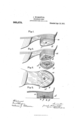
- FIG. 1 is illustrative of the heel in elevation.
- the Fig. 2 shows the heel likewies in elevation, but with disk removed and placed aside.
- Fig. 3 is an upper plan view and Fig. 1 a longitudinal section through the heel.
- the heel a is shaped, at least at its lower part, in the form of an equilateral triangle having curved sides and rounded angles.
- the bottom of the heel has fastened thereto a triangular plate 6, made preferably of metal. This is fitted with a tapped aperture 0.
- the disk or the heel-piece d to be fastened to the heel has exactly the form and size of the lower heel-parts. It carries at top a recess 6 corresponding in size and shape to the plate 6 and arranged in such a way that the disk (Z when pushed therewith over the plate 7) perfectly coincides with the heel. By this arrangement the disk (Z is kept from turning without further trouble.
- the disk can be fixed, as shown, by means of a screw f to be screwed into the tapped opening 0 of the plate Z) which with its head bears against a thin metallic plate 5/ adapted at or in the disk (Z.
- This plate g may carry, as shown, upwardly directed lugs preferably formed by the punching process, with which it engages the recess 6 and embraces the sidewalls of plate Z).
- l/Vhen disk (Z is worn along one of its sides, screw f is slackened, the disk is lifted off plate Z), and after being turned through an angle of 120 is re-attached. This operation may be repeated when the second side of the disk has become worn, so that all three sides of the disk may be consecutively utilized for standing the maximum wear.
- the disk (Z may be made of one or several layers of leather or of rubber or of any other suitable material.
- a device of the character described comprising a heel, the lower portion of which is of equilateral triangular shape with rounded angles, a disk of like shape and size, and means for adjustably securing the disk to said lower heel portion.
- a device of the character described comprising an equilateral triangular heel having curved sides and rounded angles, a disk of like shape, and means for adjustably securing the disk to the heel.
- a device of the character described comprising a heel, a triangular bottom plate secured thereto, an equilateral triangular disk having curved sides and rounded angles, and recessed to receive the bottom plate, and means for adjustably securing the disk to the heel.
Landscapes
- Motorcycle And Bicycle Frame (AREA)
- Footwear And Its Accessory, Manufacturing Method And Apparatuses (AREA)
Description
- XWJf J. WILMSHUFER. DETAGHABLB HEEL." APPLIOATION FILED AUG. 18, 1910.
989,679, Patented Apri18,19-1I.
ELM,
1H2 NORRIS PETERS 5a., wgsumamn, n. c.
JOSEPH WILMSI-IE'FER, OF DUSSELDORF, GERMANY.
DETAGHABLE HEEL.
Specification of Letters Patent.
Patented Apr. 18, 1911.
Application filed August 18, 1910. Serial No. 577,765.
To all whom it may concern:
Be it known that I, J osnrn l/Vrnnsnbrnn, a citizen of Germany, residing at Herzegstrasse 102, Dusseldorf, in the Province of Rhineland and Kingdom of Prussia, Germany, have .invented new and useful Improvements in Detachable Heels, of which the following is a specification.
The present invention contemplates a de tachable heel in which a disk, used as a heel-piece, is adjustably attached below the heel-body. When worn away at one part of its under surface, such disk is moved by turning or displacing it with another part to that side of the heel, which is more particularly subjected to wear and tear.
The essential feature of the invention lies in the fact, that the disk and the heel have at their lower part the form of an equilateral triangle having curved sides and rounded angles; thus the heel-piece or the disk, after being turned through 120 in one or the other direction, always coincides with the heel. So the arrangement allows of displacing two times or of using the disk-or the heel-tap in three positions, without it being necessary that both parts differ remarkably from the form of the heel generally in use.
The accompanying drawing, in which similar letters referto similar parts throughout the several views, shows the new arrangement in one form of embodiment.
The Figure 1 is illustrative of the heel in elevation. The Fig. 2 shows the heel likewies in elevation, but with disk removed and placed aside. Fig. 3 is an upper plan view and Fig. 1 a longitudinal section through the heel.
The heel a is shaped, at least at its lower part, in the form of an equilateral triangle having curved sides and rounded angles. The bottom of the heel has fastened thereto a triangular plate 6, made preferably of metal. This is fitted with a tapped aperture 0. The disk or the heel-piece d to be fastened to the heel has exactly the form and size of the lower heel-parts. It carries at top a recess 6 corresponding in size and shape to the plate 6 and arranged in such a way that the disk (Z when pushed therewith over the plate 7) perfectly coincides with the heel. By this arrangement the disk (Z is kept from turning without further trouble. The disk can be fixed, as shown, by means of a screw f to be screwed into the tapped opening 0 of the plate Z) which with its head bears against a thin metallic plate 5/ adapted at or in the disk (Z. This plate g may carry, as shown, upwardly directed lugs preferably formed by the punching process, with which it engages the recess 6 and embraces the sidewalls of plate Z). l/Vhen disk (Z is worn along one of its sides, screw f is slackened, the disk is lifted off plate Z), and after being turned through an angle of 120 is re-attached. This operation may be repeated when the second side of the disk has become worn, so that all three sides of the disk may be consecutively utilized for standing the maximum wear.
The disk (Z may be made of one or several layers of leather or of rubber or of any other suitable material.
I claim 1. A device of the character described, comprising a heel, the lower portion of which is of equilateral triangular shape with rounded angles, a disk of like shape and size, and means for adjustably securing the disk to said lower heel portion.
2. A device of the character described, comprising an equilateral triangular heel having curved sides and rounded angles, a disk of like shape, and means for adjustably securing the disk to the heel.
3. A device of the character described, comprising a heel, a triangular bottom plate secured thereto, an equilateral triangular disk having curved sides and rounded angles, and recessed to receive the bottom plate, and means for adjustably securing the disk to the heel.
JOSEPH WILMSHOFER. [L. s]
Witnesses:
WALTER VoNNneUr, ALFRED HnNKEL.
Copies of this patent may be obtained for five cents each, by addressing the Commissioner of Patents,
Washington, D. G.
Priority Applications (1)
| Application Number | Priority Date | Filing Date | Title |
|---|---|---|---|
| US57776510A US989679A (en) | 1910-08-18 | 1910-08-18 | Detachable heel. |
Applications Claiming Priority (1)
| Application Number | Priority Date | Filing Date | Title |
|---|---|---|---|
| US57776510A US989679A (en) | 1910-08-18 | 1910-08-18 | Detachable heel. |
Publications (1)
| Publication Number | Publication Date |
|---|---|
| US989679A true US989679A (en) | 1911-04-18 |
Family
ID=3058017
Family Applications (1)
| Application Number | Title | Priority Date | Filing Date |
|---|---|---|---|
| US57776510A Expired - Lifetime US989679A (en) | 1910-08-18 | 1910-08-18 | Detachable heel. |
Country Status (1)
| Country | Link |
|---|---|
| US (1) | US989679A (en) |
-
1910
- 1910-08-18 US US57776510A patent/US989679A/en not_active Expired - Lifetime
Similar Documents
| Publication | Publication Date | Title |
|---|---|---|
| US989679A (en) | Detachable heel. | |
| US1025571A (en) | Foot-support. | |
| USD893136S1 (en) | Cap | |
| US483931A (en) | Henry lanergan | |
| US56190A (en) | Improvement in button-holes | |
| US1101980A (en) | Game apparatus. | |
| US800680A (en) | Removable calk for horseshoes. | |
| US1359260A (en) | Universal soldering-cup | |
| US508677A (en) | Henry a | |
| US925354A (en) | Pneumatic heel for boots and shoes. | |
| US278179A (en) | Oil-can | |
| US1138234A (en) | Quoit. | |
| US92471A (en) | Improvement in picker-cushions for looms | |
| US49776A (en) | Improvement in oil-cans | |
| US146075A (en) | Improvement in joiners gages | |
| US726904A (en) | Horseshoe. | |
| US1036129A (en) | Insole-smoothing implement for shoes. | |
| US1289671A (en) | Foot-arch support. | |
| US259116A (en) | Truss | |
| US532204A (en) | Die foe | |
| USD25617S (en) | Design for a jar | |
| USD48041S (en) | Design for an india-rubber sole-pad por boots and shoes | |
| US1053731A (en) | Removable heel. | |
| US1298011A (en) | Heel. | |
| US417916A (en) | Thirds to edmund converse and ambrose t |