US989568A - Electric furnace. - Google Patents
Electric furnace. Download PDFInfo
- Publication number
- US989568A US989568A US56674110A US1910566741A US989568A US 989568 A US989568 A US 989568A US 56674110 A US56674110 A US 56674110A US 1910566741 A US1910566741 A US 1910566741A US 989568 A US989568 A US 989568A
- Authority
- US
- United States
- Prior art keywords
- furnace
- melting
- chamber
- body portion
- electric
- Prior art date
- Legal status (The legal status is an assumption and is not a legal conclusion. Google has not performed a legal analysis and makes no representation as to the accuracy of the status listed.)
- Expired - Lifetime
Links
- 230000008018 melting Effects 0.000 description 23
- 238000002844 melting Methods 0.000 description 23
- 239000000463 material Substances 0.000 description 9
- OKTJSMMVPCPJKN-UHFFFAOYSA-N Carbon Chemical compound [C] OKTJSMMVPCPJKN-UHFFFAOYSA-N 0.000 description 7
- 229910052799 carbon Inorganic materials 0.000 description 7
- 238000010438 heat treatment Methods 0.000 description 5
- 239000004927 clay Substances 0.000 description 3
- 238000010276 construction Methods 0.000 description 2
- 239000000203 mixture Substances 0.000 description 2
- 101800000535 3C-like proteinase Proteins 0.000 description 1
- 101800002396 3C-like proteinase nsp5 Proteins 0.000 description 1
- 239000004568 cement Substances 0.000 description 1
- 230000003247 decreasing effect Effects 0.000 description 1
- 239000004615 ingredient Substances 0.000 description 1
- 239000002184 metal Substances 0.000 description 1
- 235000013379 molasses Nutrition 0.000 description 1
- 238000000465 moulding Methods 0.000 description 1
Images
Classifications
-
- H—ELECTRICITY
- H05—ELECTRIC TECHNIQUES NOT OTHERWISE PROVIDED FOR
- H05B—ELECTRIC HEATING; ELECTRIC LIGHT SOURCES NOT OTHERWISE PROVIDED FOR; CIRCUIT ARRANGEMENTS FOR ELECTRIC LIGHT SOURCES, IN GENERAL
- H05B3/00—Ohmic-resistance heating
- H05B3/0014—Devices wherein the heating current flows through particular resistances
Definitions
- My invention relates to improvements in electric furnaces, and more especially to electric furnaces of the resistance type in which the heat for melting is generated by the resistance to the electric current as it passes through the wall of'the melting chamber.
- the object of my invention is to prodice a furnace having the highest resistance to the current in that part of the furnace which forms the inner wall of the melting chamber and is next to the charge to be melted.
- I can do this very nicely by making the furnace of a composition which is a mixture of carbon and a resisting material such as fire-clay.
- a composition which is a mixture of carbon and a resisting material such as fire-clay.
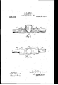
- Figure '1 is a transverse vertical section of the furnace embodying my invention
- Fig. 2 is a top View of the furnace.
- the furnace can be made of any desired size or shape, In the drawings I have illustrated one having a body portion 10 and a melting chamber 11, the melting chamber 11 being shown in the form of a crucible which can be covered if desired.
- the body portion 10 of the furnace is made of matewhich is next to the material to be melted being of a material offering a higher resistance to an electric current than the rest of the furnace. As a result it will be evident that the heat is very much higher at the point where the melting takes place than in other parts of the furnace, and in this way the furnace is not only rendeled more etficient but far more durable.
- the body portion 10 has arms 12 and 13 on opposite sides, but of course the body of the furnace may be thick enough to dispense with the arms if desired, but the arms are preferred as they simplify the construction and save material. These arms 12 and 13 are bored. out, and the carbon terminals 1/1 and 15 of relatively large size so as to be of low resistance, are fittedsnugly into the bores. When. this is done some good conducting cement should be used, and I have found ordinary molasses mixed with carbon, very suitable for the purpose. Proper electric connections are provided for the carbon terminals 14 and 15, but these are not shown in the drawings as they form no part of my present invention.
- the heating chamber "11 and the body portion 10 are formed under pressure in a mold at one and the same time. In this way when the furnace is dried, the heating chamber 11 and the body portion 10 form one continuous body, and in this way all difiiculty of forming a good electrical connection between the body portion and the heating chamber is avoided, and all possibility of arcing in the passage of an electric current from the body portion to the meltingehamber is eliminated.
- the current is turned on through the terminal 14 and passes through the arm 12, and because of its low resistance, the body portion of the furnace 'will remain comparatively cool while the melt- ,ing chamber through which the current pafles being ol nmt crial oll'ering high re sistance to the currenh will become white 'hot and will melt: materials readily.
- a the body portion 10 does not entirely surround the SltltS ol the melting chamher 11 at; 16, and as it (loos not exlentl across the bottom of it at. 17, the electric current in passing from -lhe terminals 1 1- out through the terminals 15, must pass at first. through the bottom of the heating; clunnher as it is apparent that that path will.
- I clailnz- 1 An electric resistance furnace comprising a melting chamber the walls of Which are of high reeistance, anti. a lady portion formet l on opposite sides of the melting chamber near the hotton'r, the melting ehanr her being wider and deeper than the said body portion and being also smaller at its the sitlee; tl'iereol', eaitl hotly portion being compoertl oil material of hotter conductivity than that: of the melting chamber.
- A. one-piece electric resistance furnace having a melting rhan'iher coni 'ioseil of material ol relatively high. resistance, and a hotly portion fOIIDCtl in the shape of integral arms extending froin the SltlQS oi. the melting; chamber, the Stlltl hotly portion heinncomposed of material'of better conductivity than that of the melting chamber.
- .irneleetrie furnace havii'ig a melting chamber of relatively high resistance and a hotly portion of relatively low resistance integral therewith, the lower portion of the melting chamber intersecting the body portion antl heing'of greater height than the hotly portion, whereby a current first traverses; the lower Walls of the melting chamber.
Landscapes
- Vertical, Hearth, Or Arc Furnaces (AREA)
- Furnace Details (AREA)
Description
M. R. GQNLEY.
ELECTRIC FURNACE. APPIliOATION FILED JUNE 14,1910.
- Patented A r.1s,1911,
UNITED STATES rATEN'roFFioE.
MICHAEL R. CONLEY, OF NEW YORK, N. Y., ASSIGNOR TO J. ESDAILE FLORENCE, TRUSTEE, OF NEW YORK, N. Y.
ELECTRIC FURNACE.
Application filed June 14, 1910.
Specification of Letters Patent.
Patented Apr. 18, 1911.
Serial No. 568,741.
To all whom it may concern:
Be it, known that l, .l\/lI.(,'HAEL R. (.ONLEY, of the city of New York. county of Kings, and State of New York, have invented a new and useful -.[mpro\-ement in Electric Furnaces, of which the following is a full, clear, and exact description.
My invention relates to improvements in electric furnaces, and more especially to electric furnaces of the resistance type in which the heat for melting is generated by the resistance to the electric current as it passes through the wall of'the melting chamber.
The object of my invention is to prodice a furnace having the highest resistance to the current in that part of the furnace which forms the inner wall of the melting chamber and is next to the charge to be melted. I can do this very nicely by making the furnace of a composition which is a mixture of carbon and a resisting material such as fire-clay. By molding the material so that the ingredients in that portion which constitutes the melting chamber are composed of a relatively high percentage of clay, say sixty per cent., and forty per cent. of carbon, and having the remainder of the furnace high in carbon, say eightl-y per cent. of carbon and twenty per cent. of tire-clay, itwill be seen that the body portion will be of low resistance while the part where the melting takes place will. be of high resistance, and this latter part will consequently become much hotter under the influence of a suitable current.
Reference is to be had to the accompanying drawings forming a part of this specification, inwhich similar reference characters indicate corresponding parts in all the views.
Figure '1 is a transverse vertical section of the furnace embodying my invention, and Fig. 2 is a top View of the furnace.
- The furnace can be made of any desired size or shape, In the drawings I have illustrated one having a body portion 10 and a melting chamber 11, the melting chamber 11 being shown in the form of a crucible which can be covered if desired. The body portion 10 of the furnace is made of matewhich is next to the material to be melted being of a material offering a higher resistance to an electric current than the rest of the furnace. As a result it will be evident that the heat is very much higher at the point where the melting takes place than in other parts of the furnace, and in this way the furnace is not only rendeled more etficient but far more durable.
The body portion 10 has arms 12 and 13 on opposite sides, but of course the body of the furnace may be thick enough to dispense with the arms if desired, but the arms are preferred as they simplify the construction and save material. These arms 12 and 13 are bored. out, and the carbon terminals 1/1 and 15 of relatively large size so as to be of low resistance, are fittedsnugly into the bores. When. this is done some good conducting cement should be used, and I have found ordinary molasses mixed with carbon, very suitable for the purpose. Proper electric connections are provided for the carbon terminals 14 and 15, but these are not shown in the drawings as they form no part of my present invention.
In making the furnace, the heating chamber "11 and the body portion 10 are formed under pressure in a mold at one and the same time. In this way when the furnace is dried, the heating chamber 11 and the body portion 10 form one continuous body, and in this way all difiiculty of forming a good electrical connection between the body portion and the heating chamber is avoided, and all possibility of arcing in the passage of an electric current from the body portion to the meltingehamber is eliminated.
' In practice the current is turned on through the terminal 14 and passes through the arm 12, and because of its low resistance, the body portion of the furnace 'will remain comparatively cool while the melt- ,ing chamber through which the current pafles being ol nmt crial oll'ering high re sistance to the currenh will become white 'hot and will melt: materials readily. A the body portion 10 does not entirely surround the SltltS ol the melting chamher 11 at; 16, and as it (loos not exlentl across the bottom of it at. 17, the electric current in passing from -lhe terminals 1 1- out through the terminals 15, must pass at first. through the bottom of the heating; clunnher as it is apparent that that path will. offer less resistance than through the sides. ,As a result the melting Cllill'fllJBI Will first heeoine heale l. in the bottom part, then as the SitltS are warmetl the reeistanec therein will be decreased 5,0 that part of the current will pass through the sitlee, and the entire heating chamber in a short time will he uniformly. heated to such a degree that a charge of metal or other n'iatcrial will he quickly melted.
It will be seen that I provide an electric furnace which is very simple in construction and cheap to make and owing to the close union between the melting chamber 11. and the body portion 10, the mulling chamber heing in fact. il'itegral. with the latter, a perfect electric connection.hetivcen the two is formed so that arein of the current is impossible, and the ctmnec't'ion so tlurahlc that it is impossible to tlistorh it. in the op eration of the furnace.
I clailnz- 1. An electric resistance furnace comprising a melting chamber the walls of Which are of high reeistance, anti. a lady portion formet l on opposite sides of the melting chamber near the hotton'r, the melting ehanr her being wider and deeper than the said body portion and being also smaller at its the sitlee; tl'iereol', eaitl hotly portion being compoertl oil material of hotter conductivity than that: of the melting chamber.
3. An electric. resistance l'urnaee (JUJ'Hl'H'iS- in a melting cluunher having a closed hot tom portion and anii'ilen'ralhotly portion of less ivitllh than the melting (-hamher formed -on op n-site sales thereof and connecting with the Walls of the meltingchan'iher near the hottom thereof, the hotly portion being of better conductivity than the walls of the inellin chamber.
at. A. one-piece electric resistance furnace having a melting rhan'iher coni 'ioseil of material ol relatively high. resistance, and a hotly portion fOIIDCtl in the shape of integral arms extending froin the SltlQS oi. the melting; chamber, the Stlltl hotly portion heinncomposed of material'of better conductivity than that of the melting chamber.
.irneleetrie furnace havii'ig a melting chamber of relatively high resistance and a hotly portion of relatively low resistance integral therewith, the lower portion of the melting chamber intersecting the body portion antl heing'of greater height than the hotly portion, whereby a current first traverses; the lower Walls of the melting chamber. r
MIOI IAEL R. CONLTEY.
Witnesses: I
ARTHUR G. DARNELL, lumen 13. Horonmson.
Priority Applications (1)
| Application Number | Priority Date | Filing Date | Title |
|---|---|---|---|
| US56674110A US989568A (en) | 1910-06-14 | 1910-06-14 | Electric furnace. |
Applications Claiming Priority (1)
| Application Number | Priority Date | Filing Date | Title |
|---|---|---|---|
| US56674110A US989568A (en) | 1910-06-14 | 1910-06-14 | Electric furnace. |
Publications (1)
| Publication Number | Publication Date |
|---|---|
| US989568A true US989568A (en) | 1911-04-18 |
Family
ID=3057906
Family Applications (1)
| Application Number | Title | Priority Date | Filing Date |
|---|---|---|---|
| US56674110A Expired - Lifetime US989568A (en) | 1910-06-14 | 1910-06-14 | Electric furnace. |
Country Status (1)
| Country | Link |
|---|---|
| US (1) | US989568A (en) |
-
1910
- 1910-06-14 US US56674110A patent/US989568A/en not_active Expired - Lifetime
Similar Documents
| Publication | Publication Date | Title |
|---|---|---|
| US989568A (en) | Electric furnace. | |
| US1552555A (en) | Glass-refining furnace | |
| US1679284A (en) | Process for production of self-baking electrodes | |
| US848422A (en) | Method of maintaining or increasing the fluidity of molten or semimolten materials by means of electricity. | |
| US927935A (en) | Method of manufacturing filaments for electric lamps. | |
| US865016A (en) | Electric furnace. | |
| US1645091A (en) | Electric furnace | |
| US2140228A (en) | Electrically heated furnace | |
| US859292A (en) | Electric lighting. | |
| US305817A (en) | Seph p | |
| US1552813A (en) | Electric household iron | |
| US967909A (en) | Electric furnace. | |
| US1457718A (en) | Electric furnace | |
| US870326A (en) | Electric furnace. | |
| US977303A (en) | Electric furnace. | |
| US967908A (en) | Electric furnace. | |
| US984970A (en) | Furnace for metallurgical purposes. | |
| US988936A (en) | Electric-furnace process and electric furnace. | |
| US1650675A (en) | Electric furnace | |
| US841232A (en) | Electric rheostat. | |
| US932986A (en) | Transforming smelting-furnace. | |
| US969109A (en) | Solder for incandescent-lamp filaments. | |
| US1024257A (en) | Electrode. | |
| US1134788A (en) | Electric terminal. | |
| US1111341A (en) | Method of reducing ores. |