US9894528B2 - Methods and systems for almost blank subframe (ABS) pattern selection for small cells - Google Patents
Methods and systems for almost blank subframe (ABS) pattern selection for small cells Download PDFInfo
- Publication number
- US9894528B2 US9894528B2 US14/926,237 US201514926237A US9894528B2 US 9894528 B2 US9894528 B2 US 9894528B2 US 201514926237 A US201514926237 A US 201514926237A US 9894528 B2 US9894528 B2 US 9894528B2
- Authority
- US
- United States
- Prior art keywords
- abs
- base station
- pci
- pattern
- patterns
- Prior art date
- Legal status (The legal status is an assumption and is not a legal conclusion. Google has not performed a legal analysis and makes no representation as to the accuracy of the status listed.)
- Expired - Fee Related, expires
Links
Images


Classifications
-
- H—ELECTRICITY
- H04—ELECTRIC COMMUNICATION TECHNIQUE
- H04W—WIRELESS COMMUNICATION NETWORKS
- H04W16/00—Network planning, e.g. coverage or traffic planning tools; Network deployment, e.g. resource partitioning or cells structures
- H04W16/02—Resource partitioning among network components, e.g. reuse partitioning
- H04W16/10—Dynamic resource partitioning
Definitions
- Certain embodiments relate to wireless communications. More specifically, certain embodiments relate to methods and systems for almost blank subframe (ABS) pattern selection for small cells.
- ABS almost blank subframe
- a conventional cellular network is deployed as a homogenous network of macrocell base stations.
- the macrocell base stations may all have similar antenna patterns and similar high-level transmit powers.
- small cell base stations are used to provide small coverage areas that overlap with the comparatively larger coverage areas provided by macrocell base stations.
- the small coverage areas are specifically provided in areas with high data traffic (or so called hotspots) to increase capacity.
- Examples of small cell base stations include, in order of decreasing coverage area, microcell base stations, picocell base stations, and femtocell base stations or home base stations. Small cells deployments result in more base stations that are closer to the mobile devices they serve. The increased network capacity of small cells make them a promising solution to deliver 5G throughput.
- Interference management can be a problem in small cell deployments on SFR networks due to proximity of the cells. For example, small cells can be deployed in adjacent rooms of a building. In such a scenario, the signals emitted from a base station may penetrate into an adjacent cell, causing inter-cell interference to receivers in the adjacent cell.
- 3GPP 3rd Generation Partnership Project
- LTE Long Term Evolution
- SFR single frequency reuse
- eICIC enhanced inter-cell interference coordination
- ABS almost blank subframe
- FIG. 1 illustrates an exemplary wireless communications network with two transmitters and two receivers.
- FIG. 2 illustrates three exemplary ABS patterns with periodicity of eight sub-frames and a frame size of ten sub-frames per frame.
- FIG. 3 illustrates an exemplary self-organizing network (SON) with a centralized SON controller and two distributed SON processor circuitry.
- SON self-organizing network
- FIG. 4A is a flow chart of a method to configure enhanced inter-cell interference coordination (eICIC).
- eICIC enhanced inter-cell interference coordination
- FIG. 4B is a flow chart of a method for selecting an ABS pattern based on a physical cell ID.
- FIG. 5 illustrates an exemplary list of ABS patterns.
- FIG. 6 illustrates an exemplary mapping of a base station's PCI to an ABS pattern number.
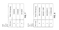
- FIG. 7 illustrates an exemplary list of ABS patterns that may be generated directly from ABS parameters.
- FIG. 8 illustrates a further exemplary list of ABS patterns that may be generated directly from ABS parameters.
- FIG. 9 illustrates a transmitter according to an exemplary embodiment of the present disclosure.
- references in the specification to “one embodiment,” “an embodiment,” “an example embodiment,” etc., indicate that the embodiment described may include a particular feature, structure, or characteristic, but every embodiment may not necessarily include the particular feature, structure, or characteristic. Moreover, such phrases are not necessarily referring to the same embodiment. Further, when a particular feature, structure, or characteristic is described in connection with an embodiment, it is submitted that it is within the knowledge of one skilled in the art to effect such feature, structure, or characteristic in connection with other embodiments whether or not explicitly described.
- FIG. 1 illustrates a block diagram of an exemplary wireless communications network with two transmitters and two receivers.
- transmitter 101 communicates data to receiver 111 via wireless link 121 .
- transmitter 102 communicates data to receiver 112 via wireless link 122 .
- the transmissions from transmitters 101 and 102 are on the same carrier frequency. Transmissions from transmitter 101 interfere with receiver 112 via interfering link 132 , and transmissions from transmitter 102 interfere with receiver 111 via interfering link 131 .
- transmitters 101 and 102 may be part of wireless base stations that are capable of both transmission and reception.
- transmitters 101 and 102 may each comprise a small cell eNodeB (eNB).
- transmitters 101 and 102 may each comprise a Home eNB (HeNB).
- Receivers 111 and 112 may be user equipment (UEs) configured to receive downlink transmissions from respective eNBs.
- UEs user equipment
- Interference at receivers 111 and 112 results when transmissions from transmitters 101 and 102 occur at the same time on the same frequency. Such interference reduces network capacity. Transmitters 101 and 102 can coordinate their transmissions to mitigate harm caused by interference while still providing high data-rate transmissions to their respective receivers. This coordination can take place in time or in frequency.
- the 3GPP Long Term Evolution (LTE) standard defines a frequency-domain type of coordination, labeled inter-cell interference coordination (ICIC), and a time-domain type of coordination, labeled enhance ICIC (eICIC).
- ICIC inter-cell interference coordination
- eICIC time-domain type of coordination
- neighboring transmitters may coordinate to periodically transmit an almost-blank sub-frame (ABS), where a transmitter does not transmit on data traffic channels but may transmit on control channels at low power.
- ABS almost-blank sub-frame
- a receiver can theoretically receive transmissions on a traffic channel from a second transmitter without interference. It is desirable for transmitters to coordinate their ABS transmissions to maximize network throughput by avoiding a scenario where neighboring transmitters both send an ABS in the same sub-frame.
- This coordination could be performed through an expensive X2-type interface between the transmitters. In certain embodiments, however, no X2 interface is required for coordination of ABS transmissions. Avoiding the use of the X2 interface, and thereby enabling base stations to choose an ABS pattern without communicating with each other, reduces overhead and cost.
- receivers 111 and 112 may provide feedback to transmitters 101 and 102 , respectively.
- This feedback may be in the form of a channel state information (CSI) report as allowed in the 3GPP LTE specification.
- the feedback may enable the transmitters 101 and 102 to schedule transmissions to the respective receivers 111 and 112 in frequencies or sub-frames having low interference.
- CSI channel state information
- FIG. 2 illustrates an exemplary set of three ABS patterns 201 , 202 , and 203 . These patterns are provided as illustrative embodiments only. The present disclosure is not limited to a specific set of ABS patterns.
- the exemplary patterns are based on a frame comprising ten sub-frames. For example, focusing on Pattern 0 201 , the first frame consists of ten sub-frames 201 . 01 - 201 . 10 . In the first frame, four of the ten sub-frames are ABSs (i.e., 201 . 01 , 201 . 02 , 201 . 09 , and 201 . 10 ).
- This ABS pattern 201 has a periodicity of eight sub-frames, meaning the ABS pattern repeats every eight sub-frames. Thus, in this embodiment, consecutive frames will not contain ABSs in identical time locations because there are 10 sub-frames in each frame. Accordingly, the second frame of this pattern 201 , shown in part as comprising 201 . 11 - 201 . 16 , does not have an ABS in its first two sub-frames 201 . 11 and 201 . 12 .
- Pattern 202 has the same periodicity as pattern 201 but is delayed in time relative to pattern 201 by two sub-frames. The result is that the ABSs of pattern 202 occur in the sub-frames immediately following the ABSs of pattern 201 .
- transmitters 101 and 102 adopt ABS patterns 201 and 202 , respectively, such that their respective transmissions to receivers 111 and 112 may be received interference-free for at least two sub-frames of each frame, namely when the other transmitter is transmitting an ABS.
- Pattern 203 also has the same periodicity as patterns 201 and 202 , but is delayed in time relative to pattern 201 by four sub-frames, and relative to pattern 202 by two sub-frames. The result is that the ABSs of pattern 203 occur in the sub-frames immediately following the ABSs of pattern 202 . Accordingly, if all three patterns are respectively adopted by adjacent transmitters, the three transmitters would take turns transmitting ABSs, with a two sub-frame period where all transmitters sent a full frame.
- FIG. 3 illustrates an exemplary self-organizing network (SON) including centralized SON (cSON) controller 301 and base stations 310 and 320 .
- the base stations 310 and 320 have respective distributed SON (dSON) processor circuitry 311 and 321 and respective transceivers 312 and 322 .
- the segmentation between dSON processor circuitry 311 , 321 and transceivers 312 , 322 may be physical or logical.
- Base stations 310 and 320 may communicate with cSON 301 via a standard interface such as the S1 interface defined by the 3GPP LTE specification.
- base stations 310 and 320 are considered “neighboring” base stations herein, when they are operate in adjacent cells, OT when their respective transmit signal amplitude or signal power is greater than a predefined threshold when received at the other base station.
- the cSON controller 301 may provide a list of possible ABS patterns to each base station 310 , 320 .
- the cSON 301 may additionally provide parameters that may aid the base stations 310 , 320 to choose an ABS pattern in a distributed fashion without direct communication between base stations 310 , 320 .
- One challenge of choosing ABS patterns in a distributed fashion is to keep neighboring base stations from choosing the same ABS pattern. If neighboring base stations choose the same ABS pattern, then their ABS sub-frames will overlap, and neither base station will benefit from an interference-free sub-frame transmission.
- the base stations 310 , 320 employ a modulo operation as part of choosing an ABS pattern.
- a modulo operation divides a first number by a second number and outputs the remainder of the first number divided by the second number as the modulus of the operation. For example, 13 modulo 4 equals 1 because 13/4 equals 31 ⁇ 4, or 3 with a remainder 1.
- the base stations 310 , 320 have respective distinct physical cell IDs (PCIs).
- the PCIs may be determined by dSON processor circuitry during an initial configuration of the base stations.
- the dSON processor circuitry chooses a PI such that PCIs of neighboring base stations have a unique modulus relative to the number of possible ABS patterns.
- the dSON can “sniff” upstream or downstream transmissions of neighboring cells to determine what PCIs are employed by neighboring base stations, which can aid the dSON in determining a suitable PCI for its own base station. For example, if there are three possible ABS patterns (as illustrated in FIG.
- the PCIs of neighboring base stations are preferably unique modulo-3, so that a division operation of each PCI by the number of ABS patterns will provide a unique remainder.
- base stations 310 , 320 utilize the modulo value as an index to choose an ABS pattern, neighboring base stations will not choose the same ABS pattern.
- a base station may have a PCI of 1, and 1 mod 3 equals 1.
- that base station may choose ABS Pattern 1 in FIG. 2 .
- a neighboring base station should have a PCI such that PCI mod 3 equals 0 or 2 so that the neighbor dSON processor circuitry chooses ABS pattern 0 or 2 .
- the dSONs 311 , 321 can receive the list of ABS patterns that are indexed 0 to (r ⁇ 1), and any provided parameters from the cSON 301 .
- the dSONs 311 , 321 can then separately select an ABS pattern from the provided list of ABS patterns using the base station's own PCI. Since the PCIs are preferably unique modulo-r, where r is the number of ABS patterns provided by the cSON 301 , adjacent base stations will be able to choose different ABS patterns such that their ABSs will not overlap.
- the list of ABS patterns provided by the cSON 301 may be represented as a set of binary sequences, with a binary ‘0’ representing a normal data sub-frame, and a binary ‘1’ representing an ABS.
- FIG. 5 provides example binary sequences, or bit mappings, for illustrative purposes.
- the cSON 301 may provide parameters that allow the dSONs 311 , 321 to derive a selected ABS pattern. This embodiment reduces the communication requirement between cSON 301 and dSONs 311 , 321 .
- the cSON 301 may provide parameters such as periodicity N, number of ABS patterns r (also termed the ABS list size), ABS repetition factor m, and offset m 0 .
- the cSON 301 may provide the same parameters to neighboring base stations. From these parameters, the pattern may be illustratively defined as a length-N binary sequence with (m/r) consecutive 1's that begin at bit (m/r)*((PCI mod r)+m 0 ).
- pattern 0 may be represented as ‘11000000,’ pattern 1 may be represented as ‘00110000,’ and pattern 2 may be represented as ‘00001100.’
- the ABS repetition factor m dictates the number of consecutive sub-frames an ABS pattern will be transmitted, whereas the periodicity is the number of sub-frames between consecutive ABS sub-frames.
- the distinguishing parameter between the three patterns in FIG. 2 is the offset m 0 , which dictates the number non-ABS sub-frames that precede the first ABS sub-frame in the pattern.
- pattern 0 has an offset of 0
- pattern 1 has an offset of 2
- pattern 2 has an offset of 4.
- FIGS. 7 and 8 provide example patterns derived from parameters N, r, m, and m 0 .
- FIG. 4A is a flow chart of a method to configure enhanced inter-cell interference coordination (eICIC).
- the method may be implemented by the dSON processor circuitry 311 , 321 , or controlled by dSON processor circuitry 311 , 321 using their respective transceivers.
- the method begins in block 410 by receiving a list of ABS patterns ⁇ a[i] ⁇ . That is, a[0] corresponds to pattern 0 , a[1] corresponds to pattern 1 , a[2] corresponds to pattern 2 , etc.
- block 410 may comprise reception of ABS parameters in addition to or instead of an express list of ABS patterns.
- the method continues in block 420 with selection of an ABS pattern.
- the selection is performed without the use of an X2 interface between neighboring base stations.
- ⁇ (PCI) PCI mod r.
- the selection function ⁇ may also be a function of parameters provided by the cSON 301 .
- Step 420 is further illustrated in FIG. 4B .
- step 421 PCIs of neighboring cells are “sniffed” by receiving signal transmissions associated with the neighboring base stations, and decoding their PCIs from the received signal transmissions.
- neighboring base stations are those having a transmit signal amplitude or power, which when received at the present base station, are equal-to or greater-than a predefined threshold.
- step 422 a PCI for the present base station is chosen that is unique modulo-r relative to those of neighboring base stations, where the parameter r represents the number of ABS patterns and may be provided by the cSON controller 301 .
- the PCI for the present base station is chosen such that the modulus of the PCI mod r function is different from those of neighboring base stations.
- the index i* is determined using the remainder of the PCI of the base station divided by r.
- the index i* can be the modulus of PCI mod r, or some offset from the modulus, or a function of modulus.
- the dSON processor circuitry chooses the ABS pattern with index i*, which can include accessing a memory that stores the r-number of ABS patterns, and/or the parameters that define the ABS patterns.
- FIG. 6 provides an illustrative mapping between PCI and selected pattern number i* based on the modulus function and the parameter r.
- the method continues in block 430 by receiving a list of power metrics for neighboring cells.
- the power metrics comprise neighboring cells' reference signal received power (RSRP) as a list ⁇ p[c] ⁇ . That is, p[0] is the RSRP for neighbor 0, etc.
- the list of power metrics is provided by a radio environment measurement (REM) component of the base station.
- REM radio environment measurement
- the list of power metrics for neighboring cells is sorted in descending order to allow for efficient processing with neighboring cells prioritized by the strength of their interference.
- the list of power metrics for neighboring cells is not sorted. The remainder of the illustrated method makes no assumption on the order of the list of power metrics for neighboring cells.
- the list of power metrics for neighboring cells is analyzed to determine whether to configure eICIC with any neighboring cells. Specifically, eICIC may be most effective in balancing throughput with interference mitigation when applied to the strongest interferers.
- an iterator index e is set to 0.
- the power metric p[c] is evaluated to determine the suitability of neighboring cell c for eICIC.
- power metric p[e] is an RSRP that is compared to a threshold value p ABS , which is the minimum interference power level that warrants eICIC such that a base station begins transmitting according to an ABS pattern.
- configuration of eICIC comprises configuring dual channel quality information (CQI) reporting for UEs in the coverage area of the base station performing the present method.
- the dual CQI reporting may be an asynchronous mode where the base station prompts a UE to report CQI for neighboring cell c according to its PCI.
- the dual CQI reporting may be as specified in the 3GPP LTE specification.
- CQI measurements for a given cell may be performed in sub-frames where an adjacent cell configured for eICIC is transmitting an ABS.
- the dual CQI reporting may enable the base stations to schedule transmissions to receivers with severe interference on sub-frames where the interfering cells transmit an ABS.
- all or parts of the disclosed methods may be re-executed to evaluate changes in network configurations or propagation conditions.
- the entire list of power metrics ⁇ p[c] ⁇ need not be evaluated in full, for example when the list is sorted in descending order.
- the method may terminate immediately after any power metric fails to exceed the eICIC threshold p ABS .
- neighbor cells that do not qualify for eICIC may qualify for conventional ICIC as defined in the 3GPP LTE specification.
- Conventional ICIC does not include ABS patterns and only coordinates interference in the frequency domain. Accordingly, the disclosed methods are compatible with performing eICIC with some neighboring cells and conventional ICIC with others.
- FIG. 5 illustrates an exemplary list of ABS patterns.
- Each bit in a bit sequence represents a sub-frame transmission, with a binary ‘1’ representing an ABS, and a binary ‘0’ representing a normal sub-frame transmission.
- the present disclosure is compatible with any ABS pattern, including those patterns that are allowed by the 3GPP LIFE specification.
- the 3GPP LTE specification allows for ABS patterns with N less than or equal to 40.
- FIG. 6 illustrates an exemplary mapping of a base station's PCI to an ABS pattern number based on parameter r.
- the ABS pattern selection function ⁇ (PCI) PCI mod r.
- neighboring base stations have unique PCIs modulo r.
- the PCI for a given base station may be determined by the dSON processor circuitry during initial configuration based on knowledge of neighboring PCIs obtained by various known methods according to the 3GPP LTE specification.
- base stations may directly report their PCIs to each other using a standard interface.
- FIG. 7 illustrates an exemplary list of ABS patterns that may be generated directly from ABS parameters provided by cSON 301 .
- (m/r) is not necessarily an integer, in which case the floor function may be employed.
- FIG. 8 illustrates a further exemplary list of ABS patterns that may be generated directly from ABS parameters provided by cSON 301 .
- the parameter in may be termed a repetition factor, and an offset of m 0 shifts the ABSs to the right by (m/r)*m 0 sub-frames.
- FIG. 9 illustrates the base station 310 according to an exemplary embodiment of the present disclosure.
- the base station 310 can include a transceiver 312 communicatively coupled to dSON processor circuitry 311 .
- the transceiver 312 includes one or more processors, circuitry, and/or logic that is configured to transmit and/or receive wireless communications via one or more wireless technologies.
- the transceiver 312 can include a transmitter 910 and a receiver 920 that have one or more processors, circuitry, and/or logic configured to transmit and receive wireless communications, respectively, via one or more antennas 930 .
- the transceiver 312 can also include (but are not limited to) a digital signal processer (DSP), modulator and/or demodulator, a digital-to-analog converter (DAC) and/or an analog-to-digital converter (ADC), and/or a frequency converter (including mixers, local oscillators, and filters) to provide some examples.
- DSP digital signal processer
- DAC digital-to-analog converter
- ADC analog-to-digital converter
- the antenna 930 may include an integer array of antennas, and that the antenna 930 may be capable of both transmitting and receiving wireless communication signals.
- the base station 310 can be configured for wireless communication utilizing a Multiple-input Multiple-output (MIMO) configuration.
- MIMO Multiple-input Multiple-output
- the transceiver 312 is configured for wireless communications conforming to one or more wireless protocols defined by 3GPP.
- the transceiver 312 is configured for wireless communications conforming to 3GPP's LTE specification.
- the transceiver 312 can be referred to as LTE transceiver 312 .
- the transceiver 312 is not limited to communication conforming to 3GPP's LTE specification, and can be configured for communications that conform to one or more other 3GPP protocols and/or one or more non-3GPP protocols.
- transceiver 312 can be referred to by one or more other 3GPP and/or non-3GPP protocols in embodiments where the transceiver 312 is configured for such other communications conforming to the other 3GPP and/or non-3GPP protocols.
- the transmitter 910 in the transceive 312 can be controlled by the dSON processor circuitry 311 to transmit wireless signals to one or more recipient mobile devices (also called “user equipment,” or “UE,” in LTE), including the transmission of wireless signals with transmit frames that are formatted according to the ABS patterns described herein.
- the receiver 920 can receive wireless signals transmitted from the UEs, including UEs that are being serviced by other neighbor base stations.
- the receiver 920 can be controlled by the dSON processor circuitry 311 to scan frequencies, in-use by neighbor base stations, to receive their associated wireless signals (e.g. “sniff”) for the purpose of decoding the PCI N of each neighbor base station, so the proper PCI can be selected for the present base station.
- the dSON processor circuitry 311 can include one or more processors (CPUs) 950 and/or circuits configured to carry out instructions to perform arithmetical, logical, and/or input/output (I/O) operations of the base station 310 and/or one or more components of the base station 310 .
- the dSON processor circuitry 311 can further include a memory 960 that stores data and/or instructions, where when the instructions are executed by the processor(s) 950 , perform the functions described herein.
- the instructions, stored in memory 960 and performed by processors 950 can include at least portions of the algorithm described in FIGS. 3, 4A, and 4B as described herein.
- the data stored in memory 960 can include the ABS patterns in list form, and their corresponding parameters that define the ABS patterns.
- the memory 960 can be any volatile and/or non-volatile memory, including, for example, read-only memory (ROM), random access memory (RAM), flash memory, a magnetic storage media, an optical disc, erasable programmable read only memory (EPROM), and programmable read only memory (PROM).
- ROM read-only memory
- RAM random access memory
- EPROM erasable programmable read only memory
- PROM programmable read only memory
- the memory 960 can be non-removable, removable, or a combination of both.
Landscapes
- Engineering & Computer Science (AREA)
- Signal Processing (AREA)
- Computer Networks & Wireless Communication (AREA)
- Mobile Radio Communication Systems (AREA)
Abstract
Description
Claims (20)
Priority Applications (1)
| Application Number | Priority Date | Filing Date | Title |
|---|---|---|---|
| US14/926,237 US9894528B2 (en) | 2015-08-14 | 2015-10-29 | Methods and systems for almost blank subframe (ABS) pattern selection for small cells |
Applications Claiming Priority (2)
| Application Number | Priority Date | Filing Date | Title |
|---|---|---|---|
| US201562205615P | 2015-08-14 | 2015-08-14 | |
| US14/926,237 US9894528B2 (en) | 2015-08-14 | 2015-10-29 | Methods and systems for almost blank subframe (ABS) pattern selection for small cells |
Publications (2)
| Publication Number | Publication Date |
|---|---|
| US20170048872A1 US20170048872A1 (en) | 2017-02-16 |
| US9894528B2 true US9894528B2 (en) | 2018-02-13 |
Family
ID=57995845
Family Applications (1)
| Application Number | Title | Priority Date | Filing Date |
|---|---|---|---|
| US14/926,237 Expired - Fee Related US9894528B2 (en) | 2015-08-14 | 2015-10-29 | Methods and systems for almost blank subframe (ABS) pattern selection for small cells |
Country Status (1)
| Country | Link |
|---|---|
| US (1) | US9894528B2 (en) |
Families Citing this family (5)
| Publication number | Priority date | Publication date | Assignee | Title |
|---|---|---|---|---|
| US10091697B1 (en) * | 2016-02-08 | 2018-10-02 | Cisco Technology, Inc. | Mitigation of uplink interference within heterogeneous wireless communications networks |
| US9894659B1 (en) * | 2016-09-29 | 2018-02-13 | Google Llc | Assigning physical-layer cell identities to base stations |
| US10212729B1 (en) * | 2016-12-12 | 2019-02-19 | Sprint Spectrum L.P. | Systems and methods for implicit information transfer |
| CN107070581B (en) * | 2016-12-29 | 2019-10-25 | 上海华为技术有限公司 | A kind of interference elimination method and base station |
| US20240163807A1 (en) * | 2022-11-15 | 2024-05-16 | Qualcomm Incorporated | Techniques for power amplifier backoff adaptation coordination |
Citations (3)
| Publication number | Priority date | Publication date | Assignee | Title |
|---|---|---|---|---|
| US20130194950A1 (en) * | 2012-01-27 | 2013-08-01 | Interdigital Patent Holdings, Inc. | Systems and/or methods for managing or improving interference between cells |
| US20140044059A1 (en) * | 2012-08-07 | 2014-02-13 | Fujitsu Limited | Small-scale base station, communication system, and communication method |
| US20160192339A1 (en) * | 2013-08-12 | 2016-06-30 | Telefonaktiebolaget L M Ericsson (Publ) | Clustered Periodic Gaps for Measurements in a Heterogeneous Network |
-
2015
- 2015-10-29 US US14/926,237 patent/US9894528B2/en not_active Expired - Fee Related
Patent Citations (3)
| Publication number | Priority date | Publication date | Assignee | Title |
|---|---|---|---|---|
| US20130194950A1 (en) * | 2012-01-27 | 2013-08-01 | Interdigital Patent Holdings, Inc. | Systems and/or methods for managing or improving interference between cells |
| US20140044059A1 (en) * | 2012-08-07 | 2014-02-13 | Fujitsu Limited | Small-scale base station, communication system, and communication method |
| US20160192339A1 (en) * | 2013-08-12 | 2016-06-30 | Telefonaktiebolaget L M Ericsson (Publ) | Clustered Periodic Gaps for Measurements in a Heterogeneous Network |
Also Published As
| Publication number | Publication date |
|---|---|
| US20170048872A1 (en) | 2017-02-16 |
Similar Documents
| Publication | Publication Date | Title |
|---|---|---|
| US10805928B2 (en) | Communications in a wireless network for carrier selection and switching | |
| JP6712791B2 (en) | Base station, communication method, and integrated circuit | |
| US10433269B2 (en) | Method and system for integrated backhaul and wireless access network | |
| EP2630817B1 (en) | Method and controller for self-optimized inter-cell interference coordination | |
| US10382153B2 (en) | Methods and radio network nodes for measuring interference | |
| EP2753037B1 (en) | Method and device for interference control | |
| CA2795976C (en) | Apparatus and method for adaptive transmission during almost blank subframes in a wireless communication network | |
| US9490946B2 (en) | Interference coordination method and base station | |
| US9313004B2 (en) | Method and system for dynamic allocation of resources in a cellular network | |
| CN103202056B (en) | Method and network node for configuring almost blank subframe transmission mode and corresponding measurement mode to reduce inter-cell interference in heterogeneous cellular radio communication system | |
| US8868091B2 (en) | Methods and apparatus for facilitating inter-cell interference coordination via over the air load indicator and relative narrowband transmit power | |
| EP2648446B1 (en) | Method, system, and device for confirming uplink-downlink configuration | |
| EP3125618B1 (en) | System and method to facilitate small cell uplink power control in a network environment | |
| US20210014016A1 (en) | Reference signal transmission method and apparatus | |
| US20130303167A1 (en) | COORDINATED DYNAMIC POINT SELECTION (DPS) WITH CELL RANGE EXPANSION IN A COORDINATED MULTIPOINT (CoMP) SYSTEM | |
| US9642135B2 (en) | Method and apparatus for management of protected resource in a heterogeneous network | |
| EP2763446B1 (en) | Method, user device and base station for measuring channel state information | |
| KR20110057464A (en) | Method and apparatus for performing cooperative communication in a wireless communication system | |
| US20120309292A1 (en) | Communication control method and small-or-medium-scale base station | |
| EP4260646B1 (en) | Simultaneous transmit and receive (str) multi-link operation | |
| US9894528B2 (en) | Methods and systems for almost blank subframe (ABS) pattern selection for small cells | |
| US20140376517A1 (en) | Opportunistic activation of relays in cloud radio access networks | |
| JP2016541170A (en) | Mobility management method, apparatus and system | |
| CN110662253B (en) | Method and apparatus for carrier allocation | |
| US20230412339A1 (en) | System and method for reference signaling design and configuration |
Legal Events
| Date | Code | Title | Description |
|---|---|---|---|
| AS | Assignment |
Owner name: BROADCOM CORPORATION, CALIFORNIA Free format text: ASSIGNMENT OF ASSIGNORS INTEREST;ASSIGNORS:CHIU, FU-HSUAN;YUE, GUOSEN;SIGNING DATES FROM 20151012 TO 20151013;REEL/FRAME:036914/0184 |
|
| AS | Assignment |
Owner name: BANK OF AMERICA, N.A., AS COLLATERAL AGENT, NORTH CAROLINA Free format text: PATENT SECURITY AGREEMENT;ASSIGNOR:BROADCOM CORPORATION;REEL/FRAME:037806/0001 Effective date: 20160201 Owner name: BANK OF AMERICA, N.A., AS COLLATERAL AGENT, NORTH Free format text: PATENT SECURITY AGREEMENT;ASSIGNOR:BROADCOM CORPORATION;REEL/FRAME:037806/0001 Effective date: 20160201 |
|
| AS | Assignment |
Owner name: AVAGO TECHNOLOGIES GENERAL IP (SINGAPORE) PTE. LTD., SINGAPORE Free format text: ASSIGNMENT OF ASSIGNORS INTEREST;ASSIGNOR:BROADCOM CORPORATION;REEL/FRAME:041706/0001 Effective date: 20170120 Owner name: AVAGO TECHNOLOGIES GENERAL IP (SINGAPORE) PTE. LTD Free format text: ASSIGNMENT OF ASSIGNORS INTEREST;ASSIGNOR:BROADCOM CORPORATION;REEL/FRAME:041706/0001 Effective date: 20170120 |
|
| AS | Assignment |
Owner name: BROADCOM CORPORATION, CALIFORNIA Free format text: TERMINATION AND RELEASE OF SECURITY INTEREST IN PATENTS;ASSIGNOR:BANK OF AMERICA, N.A., AS COLLATERAL AGENT;REEL/FRAME:041712/0001 Effective date: 20170119 |
|
| STCF | Information on status: patent grant |
Free format text: PATENTED CASE |
|
| AS | Assignment |
Owner name: AVAGO TECHNOLOGIES INTERNATIONAL SALES PTE. LIMITE Free format text: MERGER;ASSIGNOR:AVAGO TECHNOLOGIES GENERAL IP (SINGAPORE) PTE. LTD.;REEL/FRAME:047422/0464 Effective date: 20180509 |
|
| AS | Assignment |
Owner name: AVAGO TECHNOLOGIES INTERNATIONAL SALES PTE. LIMITE Free format text: CORRECTIVE ASSIGNMENT TO CORRECT THE EXECUTION DATE PREVIOUSLY RECORDED AT REEL: 047422 FRAME: 0464. ASSIGNOR(S) HEREBY CONFIRMS THE MERGER;ASSIGNOR:AVAGO TECHNOLOGIES GENERAL IP (SINGAPORE) PTE. LTD.;REEL/FRAME:048883/0702 Effective date: 20180905 |
|
| CC | Certificate of correction | ||
| MAFP | Maintenance fee payment |
Free format text: PAYMENT OF MAINTENANCE FEE, 4TH YEAR, LARGE ENTITY (ORIGINAL EVENT CODE: M1551); ENTITY STATUS OF PATENT OWNER: LARGE ENTITY Year of fee payment: 4 |
|
| FEPP | Fee payment procedure |
Free format text: MAINTENANCE FEE REMINDER MAILED (ORIGINAL EVENT CODE: REM.); ENTITY STATUS OF PATENT OWNER: LARGE ENTITY |
|
| LAPS | Lapse for failure to pay maintenance fees |
Free format text: PATENT EXPIRED FOR FAILURE TO PAY MAINTENANCE FEES (ORIGINAL EVENT CODE: EXP.); ENTITY STATUS OF PATENT OWNER: LARGE ENTITY |
|
| STCH | Information on status: patent discontinuation |
Free format text: PATENT EXPIRED DUE TO NONPAYMENT OF MAINTENANCE FEES UNDER 37 CFR 1.362 |
|
| FP | Lapsed due to failure to pay maintenance fee |
Effective date: 20260213 |