US9894253B2 - Portable device, communication system, communication connection method, and computer-readable recording medium - Google Patents
Portable device, communication system, communication connection method, and computer-readable recording medium Download PDFInfo
- Publication number
- US9894253B2 US9894253B2 US14/974,459 US201514974459A US9894253B2 US 9894253 B2 US9894253 B2 US 9894253B2 US 201514974459 A US201514974459 A US 201514974459A US 9894253 B2 US9894253 B2 US 9894253B2
- Authority
- US
- United States
- Prior art keywords
- communication
- mode
- portable device
- connection
- unit
- Prior art date
- Legal status (The legal status is an assumption and is not a legal conclusion. Google has not performed a legal analysis and makes no representation as to the accuracy of the status listed.)
- Expired - Fee Related
Links
Images


Classifications
-
- H04N5/2254—
-
- H—ELECTRICITY
- H04—ELECTRIC COMMUNICATION TECHNIQUE
- H04W—WIRELESS COMMUNICATION NETWORKS
- H04W52/00—Power management, e.g. Transmission Power Control [TPC] or power classes
- H04W52/02—Power saving arrangements
- H04W52/0209—Power saving arrangements in terminal devices
- H04W52/0225—Power saving arrangements in terminal devices using monitoring of external events, e.g. the presence of a signal
- H04W52/0229—Power saving arrangements in terminal devices using monitoring of external events, e.g. the presence of a signal where the received signal is a wanted signal
-
- H—ELECTRICITY
- H04—ELECTRIC COMMUNICATION TECHNIQUE
- H04N—PICTORIAL COMMUNICATION, e.g. TELEVISION
- H04N23/00—Cameras or camera modules comprising electronic image sensors; Control thereof
- H04N23/60—Control of cameras or camera modules
- H04N23/66—Remote control of cameras or camera parts, e.g. by remote control devices
- H04N23/661—Transmitting camera control signals through networks, e.g. control via the Internet
-
- H—ELECTRICITY
- H04—ELECTRIC COMMUNICATION TECHNIQUE
- H04N—PICTORIAL COMMUNICATION, e.g. TELEVISION
- H04N23/00—Cameras or camera modules comprising electronic image sensors; Control thereof
- H04N23/60—Control of cameras or camera modules
- H04N23/667—Camera operation mode switching, e.g. between still and video, sport and normal or high- and low-resolution modes
-
- H04N5/23203—
-
- H04N5/23206—
-
- H04N5/23245—
-
- Y02B60/50—
-
- Y—GENERAL TAGGING OF NEW TECHNOLOGICAL DEVELOPMENTS; GENERAL TAGGING OF CROSS-SECTIONAL TECHNOLOGIES SPANNING OVER SEVERAL SECTIONS OF THE IPC; TECHNICAL SUBJECTS COVERED BY FORMER USPC CROSS-REFERENCE ART COLLECTIONS [XRACs] AND DIGESTS
- Y02—TECHNOLOGIES OR APPLICATIONS FOR MITIGATION OR ADAPTATION AGAINST CLIMATE CHANGE
- Y02B—CLIMATE CHANGE MITIGATION TECHNOLOGIES RELATED TO BUILDINGS, e.g. HOUSING, HOUSE APPLIANCES OR RELATED END-USER APPLICATIONS
- Y02B70/00—Technologies for an efficient end-user side electric power management and consumption
- Y02B70/10—Technologies improving the efficiency by using switched-mode power supplies [SMPS], i.e. efficient power electronics conversion e.g. power factor correction or reduction of losses in power supplies or efficient standby modes
-
- Y—GENERAL TAGGING OF NEW TECHNOLOGICAL DEVELOPMENTS; GENERAL TAGGING OF CROSS-SECTIONAL TECHNOLOGIES SPANNING OVER SEVERAL SECTIONS OF THE IPC; TECHNICAL SUBJECTS COVERED BY FORMER USPC CROSS-REFERENCE ART COLLECTIONS [XRACs] AND DIGESTS
- Y02—TECHNOLOGIES OR APPLICATIONS FOR MITIGATION OR ADAPTATION AGAINST CLIMATE CHANGE
- Y02D—CLIMATE CHANGE MITIGATION TECHNOLOGIES IN INFORMATION AND COMMUNICATION TECHNOLOGIES [ICT], I.E. INFORMATION AND COMMUNICATION TECHNOLOGIES AIMING AT THE REDUCTION OF THEIR OWN ENERGY USE
- Y02D30/00—Reducing energy consumption in communication networks
- Y02D30/70—Reducing energy consumption in communication networks in wireless communication networks
Definitions
- the present invention relates to a portable device, a communication system, a communication connection method, and a computer-readable recording medium.
- Japanese Laid-open Patent Publication No. 2003-250079 describes a technology associated with remote control of an imaging device by using a communication device.
- the communication device sequentially receives image data transmitted from the imaging device, and sequentially displays live-view images corresponding to the image data on a display unit provided on the communication device.
- a camera user inputs a capturing operation to the communication device to allow capturing by the imaging device at a desired time, while checking the live-view images displayed on the display unit of the communication device.
- a capturing instruction is transmitted from the communication device to the imaging device.
- the imaging device having received this capturing instruction generates image data of a subject by imaging the subject, and transmits the generated image data to the communication device.
- the imaging device determines a communication state for each of a plurality of communication channels provided for communication with the communication device. Then, the imaging device establishes communication connection with the communication device by using a communication channel in a preferable communication state in the plurality of communication channels.
- a portable device includes: a first communication unit configured to communicatively connect with an external communication device by using any one of a plurality of communication channels; a communication state determination unit configured to determine a communication state for each of the plurality of communication channels; a mode switching unit configured to switch a communication mode of the portable device between: a stable communication mode for establishing communication connection with the communication device by using a communication channel in a preferable communication state in the plurality of communication channels in accordance with a determination result obtained by the communication state determination unit; and a connection priority communication mode for establishing communication connection with the communication device by using a predetermined communication channel in the plurality of communication channels without determination by the communication state determination unit; and a communication controller configured to start communication connection with the communication device via the first communication unit in the communication mode selected by the mode switching unit.
- FIG. 1 is a view schematically illustrating a configuration of a communication system according to a first embodiment of the present invention
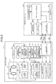
- FIG. 2 is a block diagram illustrating the configuration of the communication system illustrated in FIG. 1 ;
- FIG. 3 is a flowchart illustrating an operation of a lens-type camera illustrated in FIGS. 1 and 2 ;
- FIG. 4 is a flowchart illustrating an operation of a communication device illustrated in FIGS. 1 and 2 ;
- FIG. 5 is a block diagram illustrating a communication system according to a second embodiment of the present invention.
- FIG. 6 is a flowchart illustrating an operation of a lens-type camera illustrated in FIG. 5 ;
- FIG. 7 is a flowchart illustrating an operation of a communication device illustrated in FIG. 5 ;
- FIG. 8 is a block diagram illustrating a configuration of a communication system according to a third embodiment of the present invention.
- FIG. 9 is a block diagram illustrating a configuration of a communication system according to a fourth embodiment of the present invention.
- FIG. 1 is a view schematically illustrating a configuration of a communication system 1 according to a first embodiment of the present invention.
- FIG. 2 is a block diagram illustrating the configuration of the communication system 1 .
- the communication system 1 is a system which includes a lens-type camera 2 and a communication device 3 connected with each other such that information is transmittable and receivable to and from each other via wireless communication, and an attachment 4 ( FIG. 1 ), as a system realizing remote control of the lens-type camera 2 by using the communication device 3 .
- the attachment 4 is a component which mechanically connects the lens-type camera 2 and the communication device 3 . More specifically, the attachment 4 is attached to a rear surface of the communication device 3 as illustrated in FIG. 1 .
- the attachment 4 includes an attachment hole 4 A which is circular in the plan view and receives the lens-type camera 2 .
- the communication system 1 has a general shape like a digital camera when the lens-type camera 2 and the communication device 3 are mechanically connected with each other via the attachment 4 .
- the attachment 4 included in the communication system 1 is not an essential component of the communication system 1 , and may be eliminated from the communication system 1 .
- a main part of the present invention included in a configuration of the lens-type camera 2 is hereinafter chiefly described.
- the lens-type camera 2 includes an optical system 21 , a driving unit 22 , a position detector 23 , an operating unit 24 , a clock unit 25 , an imaging unit 26 , a camera-side memory unit 27 , a camera-side recording unit 28 , a camera-side communication unit 29 , and a camera-side controller 30 .
- the respective components 21 through 30 are housed in a lens barrel 20 ( FIG. 1 ) which generally has a substantially cylindrical shape. Accordingly, the lens-type camera 2 generally has a substantially similar shape as a general shape of a so-called interchangeable lens as illustrated in FIG. 1 .
- the optical system 21 condenses light from a predetermined visual field area, and forms an image of the condensed light on an imaging surface of an imaging device (not shown) constituting the imaging unit 26 .
- the optical system 21 includes a zoom lens 211 and a focus lens 212 as illustrated in FIG. 2 .
- the zoom lens 211 is constituted by one or a plurality of lenses, and shifts along an optical axis indicated by a broken line in FIG. 2 to change zoom magnification of the optical system 21 .
- the focus lens 212 is constituted by one or a plurality of lenses, and shifts along the optical axis indicated by the broken line in FIG. 2 to change a focal position and a focal distance of the optical system 21 .
- the driving unit 22 moves the respective lenses 211 and 212 constituting the optical system 21 along the optical axis under control by the camera-side controller 30 . As illustrated in FIG. 2 , the driving unit 22 includes a zoom driving unit 221 and a focus driving unit 222 .
- the zoom driving unit 221 is constituted by a stepping motor or a DC motor, for example, and moves the zoom lens 211 along the optical axis.
- the focus driving unit 222 is constituted by a stepping motor or a DC motor, for example, and moves the focus lens 212 along the optical axis.
- the position detector 23 detects positions of the respective lenses 211 and 212 constituting the optical system 21 on the optical axis.
- the position detector 23 includes a zoom position detector 231 and a focus position detector 232 as illustrated in FIG. 2 .
- the zoom position detector 231 is constituted by a photo-interrupter or the like, and detects a position of the zoom lens 211 on the optical axis shifted by the zoom driving unit 221 .
- the zoom position detector 231 converts an amount of rotation of a driving motor contained in the zoom driving unit 221 into a pulse number, and detects the position of the zoom lens 211 on the optical axis from an infinity-based reference position based on the converted pulse number.
- the focus position detector 232 is constituted by a photo-interrupter or the like, and detects a position of the focus lens 212 on the optical axis shifted by the focus driving unit 222 by a method similar to the method of the zoom position detector 231 .
- the operating unit 24 is constituted by an operation ring provided on a circumference of the lens barrel 20 , or buttons or switches provided on an outer surface of the lens barrel 20 .
- the operating unit 24 receives user operations such as a start/end operation of the lens-type camera 2 (on/off operation of the lens-type camera 2 ), a position change operation for changing positions of the zoom lens 211 and the focus lens 212 on the optical axis within the optical system 21 , an capturing operation, and a communication end operation for ending communication with the communication device 3 .
- the operating unit 24 having received these operations outputs signals corresponding to the user operations to the camera-side controller 30 .
- the clock unit 25 has a time measuring function, and further has a function of generating date and time information (hereinafter referred to as time stamp) concerning date and time of imaging executed by the imaging unit 26 .
- the time stamp generated by the clock unit 25 is output to the camera-side controller 30 .
- a time stamp may be acquired through communication with other devices at the time of capturing in another application example.
- the imaging unit 26 generates image data by imaging a subject under control by the camera-side controller 30 .
- the imaging unit 26 is constituted by an imaging device such as a CCD (Charge Coupled Device) which receives an image of a subject formed by the optical system 21 and converts the image into an electric signal, a signal processing unit which generates digital image data by performing signal processing (e.g., A/D conversion) for the electric signals (analog signals) received from the imaging device, and other components.
- CCD Charge Coupled Device
- Image data sequentially generated by the imaging unit 26 (hereinafter referred to as live-view image data) is sequentially stored in the camera-side memory unit 27 under control by the camera-side controller 30 , in a state that a time stamp concerning date and time and the like of generation of live-view image data has been added to the corresponding live-view image data.
- image data generated by the imaging unit 26 in accordance with an capturing operation input to the lens-type camera 2 (operating unit 24 ) or the communication device 3 by the camera user (this data is hereinafter referred to as capturing image data) is stored in the camera-side recording unit 28 , in a state that a time stamp concerning date and time of generation of capturing image data has been added to the corresponding capturing image data.
- the camera-side memory unit 27 sequentially stores live-view image data (including time stamp) generated by the imaging unit 26 .
- the camera-side recording unit 28 records various types of programs executed by the camera-side controller 30 , and characteristic information concerning characteristics of the optical system 21 , such as magnification, focal distance, angle of view, aberration, and F-number (brightness) of the optical system 21 , for example.
- the camera-side recording unit 28 further records capturing image data (including time stamp) generated by the imaging unit 26 in accordance with an capturing operation input to the lens-type camera 2 (operating unit 24 ) or the communication device 3 by the camera user under control by the camera-side controller 30 .
- the camera-side communication unit 29 functions as a first communication unit according to the present invention.
- the camera-side communication unit 29 also functions as a communication interface for realizing wireless communication of various types of data including signals necessary for communication with the communication device 3 by using any one of first through nth communication channels under control by the camera-side controller 30 .
- FIGS. 1 and 2 illustrate only the single communication device 3 for convenience of explanation.
- the camera-side communication unit 29 is configured to establish communication connection with the plurality of communication devices 3 as well as communication connection with only the single communication device 3 .
- Wi-Fi Wireless Fidelity
- WiMAX Worldwide Interoperability for Microwave Access
- the device functions exhibit a relation of an access point and a station on an assumed local network.
- a general connection process is realized when the station connects with a wireless network constituted by the access point.
- Connection sequences are roughly divided into Steps 1 and 2 . More specifically, the access point gives notification indicating a network identifier (SSID) of the access point by using any one of the first through nth communication channels (Step 1 ). Then, the station searches the communication channel through which the notification of the network identifier (SSID) has been given from the first through nth communication channels, and connects with the access point by using the selected communication channel based on the search (Step 2 ).
- the lens-type camera 2 corresponds to the access point, while the communication device 3 corresponds to the station. According to this communication system, communication is allowed at a speed of 10 megabits per second or higher. Accordingly, images are transmittable at a high speed.
- the camera-side controller 30 includes a CPU (Central Process Unit) and others, and controls the overall operation of the lens-type camera 2 in accordance with signals received from the operating unit 24 , and signals received from the communication device 3 via the camera-side communication unit 29 .
- the camera-side controller 30 includes a communication state determination unit 301 , a mode switching unit 302 , a communication controller 303 , and an imaging controller 304 as illustrated in FIG. 2 .
- the communication state determination unit 301 determines whether or not a communication state is preferable for each of the first through nth communication channels, or for the communication channel currently used.
- the communication state determination unit 301 detects a state of use by other devices for each of the first through nth communication channels before a start of a communication connection establishment process. Then, the communication state determination unit 301 determines a communication channel not used by other devices, or a communication channel used by a relatively small number of devices in comparison with other communication channels, as a communication channel in a preferable communication state.
- the communication state determination unit 301 further detects a throughput of the communication channel currently used after the communication connection establishment process. When the throughput is a predetermined value or larger, the communication state determination unit 301 determines that the communication state of the corresponding communication channel is preferable. On the other hand, when the throughput is smaller than the predetermined value, the communication state determination unit 301 determines that the communication state of the corresponding communication channel is not preferable.
- the communication state determination unit 301 further determines that the communication state of the communication channel is not preferable when communication connection is difficult to establish in a state that an authentication request does not reach a destination device, or that a response to an authentication request does not reach the device even after arrival of the request at the destination device, for example, during the communication connection establishment process.
- the mode switching unit 302 switches a communication mode of the lens-type camera 2 to a stable communication mode or a connection priority communication mode.
- the stable communication mode in this context is a communication mode for establishing communication connection with the communication device 3 by using a communication channel in a preferable communication state (hereinafter referred to as state preferable channel) in the first through nth communication channels in accordance with a determination result obtained by the communication state determination unit 301 .
- state preferable channel a communication channel in a preferable communication state
- connection priority communication mode is a communication mode for establishing communication connection with the communication device 3 by using a communication channel selected beforehand (hereinafter referred to as default channel) from the first through nth communication channels without determination by the communication state determination unit 301 .
- the communication controller 303 starts (establishes) communication connection with the communication device 3 via the camera-side communication unit 29 in the communication mode selected by the mode switching unit 302 by using a communication system such as Wi-Fi (registered trademark).
- a communication system such as Wi-Fi (registered trademark).
- the communication controller 303 receives a capturing instruction or a capturing image data transmission request from the communication device 3 .
- the communication controller 303 transmits latest capturing image data recorded in the camera-side recording unit 28 to the communication device 3 in response to the received instruction or request.
- the “latest” data in this context refers to latest data in view of time and date based on the time stamp. (The same is applicable hereinafter.)
- the communication controller 303 sequentially transmits latest live-view image data stored in the camera-side memory unit 27 to the communication device 3 , and also transmits, to the communication device 3 , characteristic information recorded in the camera-side recording unit 28 , and lens position information concerning respective positions of the zoom lens 211 and the focus lens 212 detected by the position detector 23 .
- the communication controller 303 further receives a change instruction for changing capturing parameters from the communication device 3 .
- the capturing parameters in this context include focal distance, focal position, F-number, shutter speed, exposure value, ISO speed, chroma, and hue, for example.
- the imaging controller 304 adds a time stamp concerning time and date of generation of live-view image data to the corresponding live-view image data generated by the imaging unit 26 , and sequentially stores the live-view image data in the camera-side memory unit 27 .
- the imaging controller 304 further allows the imaging unit 26 to image a subject in accordance with an capturing operation input to the lens-type camera 2 (operating unit 24 ) or the communication device 3 (i.e., capturing instruction received from the communication device 3 via the camera-side communication unit 29 ) by the camera user.
- the imaging controller 304 adds a time stamp concerning time and date of generation of capturing image data to the corresponding image data generated by the imaging unit 26 , and records the capturing image data in the camera-side recording unit 28 .
- the imaging controller 304 controls operations of the driving unit 22 and the like in accordance with the change instruction for changing the capturing parameters received from the communication device 3 via the camera-side communication unit 29 to change the capturing parameters.
- a main part of the present invention included in a configuration of the communication device 3 is hereinafter chiefly described.
- the communication device 3 is constituted by a digital camera, a digital video camera, a cellular phone, or a tablet-type portable device, for example. (An example of a cellular phone is illustrated in FIG. 2 .) As illustrated in FIG. 2 , the communication device 3 includes an input unit 31 , a display unit 32 , a device-side memory unit 33 , a device-side recording unit 34 , a device-side communication unit 35 , and a device-side controller 36 .
- the input unit 31 is constituted by buttons, switches, a touch panel or the like, and outputs instruction signals corresponding to the user operations to the device-side controller 36 .
- the input unit 31 functions as an operation receiving unit according to the present invention.
- the display unit 32 is constituted by a liquid crystal or organic EL (Electro Luminescence) display panel, for example.
- the display unit 32 displays a predetermined image under control by the device-side controller 36 .
- the device-side memory unit 33 stores live-view image data (including time stamp), characteristic information, lens position information and others received from the lens-type camera 2 via the device-side communication unit 35 .
- the device-side recording unit 34 records various types of programs (including communication connection program according to the present invention) executed by the device-side controller 36 , and various types of data used during execution of the programs, and others, and records capturing image data (including time stamp) received from the lens-type camera 2 via the device-side communication unit 35 .
- the device-side communication unit 35 is a communication interface provided for wireless communication of various types of data including signals necessary for communication with the lens-type camera 2 via any one of the first through nth communication channels by using a communication system such as Wi-Fi (registered trademark) under control by the device-side controller 36 .
- a communication system such as Wi-Fi (registered trademark) under control by the device-side controller 36 .
- the device-side controller 36 is constituted by a CPU and others, and controls overall operations of the communication device 3 by issuing instructions and transferring data to respective units constituting the communication device 3 in accordance with instruction signals received from the input unit 31 .
- An operation of the lens-type camera 2 (communication connection method according to the present invention), and an operation of the communication device 3 are sequentially described in this order as the operations of the communication system 1 .
- FIG. 3 is a flowchart illustrating the operation of the lens-type camera 2 .
- the mode switching unit 302 determines whether or not a first condition is met (step S 102 ).
- the “first condition” in this context is a condition that the lens-type camera 2 is set to the shooting mode (mode for capturing a still image or the like). More specifically, the mode switching unit 302 determines that the first condition is met when the lens-type camera 2 is set to the shooting mode. On the other hand, the mode switching unit 302 determines that the first condition is not met when the lens-type camera 2 is set to not the shooting mode but a playback mode (mode for transmitting capturing image data recorded in the camera-side recording unit 28 to the communication device 3 ).
- step S 102 When it is determined that the first condition is met (step S 102 : Yes), the mode switching unit 302 switches the communication mode of the lens-type camera 2 to the connection priority communication mode (step S 103 : mode switching step).
- step S 102 When it is determined that the first condition is not met (step S 102 : No), the lens-type camera 2 shifts to step S 113 .
- the communication controller 303 gives notification of a network identifier (SSID) via the camera-side communication unit 29 by using a default channel (such as first communication channel) in the first through nth communication channels to start (establish) communication connection with the communication device(s) 3 (only single communication device 3 or the plurality of communication devices 3 ) by using the default channel (step S 104 : communication control step).
- SSID network identifier
- the camera-side controller 30 executes setups of the optical system 21 (such as positioning of the zoom lens 211 and focus lens 212 at initial positions on the optical axis) to shift to an imaging-enabled state, and allows the imaging unit 26 to start imaging (step S 105 ).
- Live-view image data (including time stamp) generated by the imaging unit 26 is sequentially stored in the camera-side memory unit 27 .
- the process in step S 105 may be executed only when “Yes” in step S 107 .
- the time stamp need not be included in the live-view image data.
- the communication controller 303 transmits latest live-view image data (including time stamp) stored in the camera-side memory unit 27 to the communication device(s) 3 (only single communication device 3 when communication connection is established only with the single communication device 3 , or the plurality of communication devices 3 when communication connection is established with the plurality of communication devices 3 ) via the camera-side communication unit 29 by using the default channel (step S 106 ).
- the imaging controller 304 determines whether or not a capturing instruction has been received from the communication device 3 via the camera-side communication unit 29 (step S 107 ).
- the imaging controller 304 allows the imaging unit 26 to execute imaging (step S 108 ). Capturing image data generated by the imaging unit 26 (including time stamp) is recorded in the camera-side recording unit 28 .
- step S 107 When it is determined that the capturing instruction has not been received (step S 107 : No), the lens-type camera 2 shifts to step S 109 .
- step S 109 determines whether or not the communication state of the default channel is preferable.
- step S 110 When it is determined that the communication state of the default channel is preferable in step S 109 (step S 110 : Yes), the lens-type camera 2 shifts to step S 112 .
- step S 110 determines whether or not a second condition is met.
- the “second condition” in this context is a condition that communication connection is established between the lens-type camera 2 and the plurality of communication devices 3 by using the default channel. More specifically, the mode switching unit 302 determines that the second condition is met when the communication connection is established with the plurality of communication devices 3 by using the default channel in step S 104 . On the other hand, the mode switching unit 302 determines that the second condition is not met when the communication connection is established only with the single communication device 3 by using the default channel in step S 104 .
- step S 111 When it is determined that the second condition is met (step S 111 : Yes), the mode switching unit 302 does not switch the communication mode of the lens-type camera 2 , but continues the connection priority communication mode. Then, the camera-side controller 30 determines whether or not a communication end operation has been input to the operating unit 24 by the camera user (step S 112 ). When it is determined that the communication state of the default channel is preferable in step S 109 (step S 110 : Yes), step S 112 is similarly executed.
- step S 112 When it is determined that the communication end operation has been input (step S 112 : Yes), the lens-type camera 2 ends this process.
- step S 112 When it is determined that the communication end operation has not been input (step S 112 : No), the lens-type camera 2 returns to step S 107 .
- steps S 107 through S 112 are executed after steps S 105 and S 106 for convenience of explanation. However, steps S 105 and S 106 and steps S 107 through S 112 are simultaneously executed in parallel in a practical situation.
- step S 111 When it is determined that the second condition is not met in step S 111 (step S 111 : No), or when it is determined that the first condition is not met in step S 102 (step S 102 : No), the mode switching unit 302 switches the communication mode of the lens-type camera 2 to the stable communication mode (step S 113 : mode switching step).
- the communication state determination unit 301 determines whether or not the communication state of the communication channel is preferable for each of the first through nth communication channels (step S 114 ).
- the communication controller 303 may end communication connection with the communication device(s) 3 before determining the communication state.
- the communication controller 303 gives notification of the network identifier (SSID) via the camera-side communication unit 29 by using a state preferable channel exhibiting a preferable communication state in the first through nth communication channels, and starts (establishes) communication connection with the communication device(s) 3 (the single communication device 3 or the plurality of communication devices 3 ) (step S 115 : communication control step).
- SSID network identifier
- the camera-side controller 30 determines whether or not the lens-type camera 2 is set to the shooting mode (step S 116 ).
- step S 116 When it is determined that the lens-type camera 2 is not set to the shooting mode in step S 116 (step S 116 : No), the camera-side controller 30 executes a process in the playback mode (step S 117 ). Then, the lens-type camera 2 shifts to step S 124 .
- step S 116 When it is determined that the lens-type camera 2 is set to the shooting mode in step S 116 (step S 116 : Yes), the camera-side controller 30 executes steps S 118 through S 121 similar to steps S 105 through S 108 .
- step S 120 determines whether or not an capturing image data transmission request has been received from the communication device 3 via the camera-side communication unit 29 by using the state preferable channel (step S 122 ).
- step S 122 When it is determined that the capturing image data transmission request has not been received (step S 122 : No), the lens-type camera 2 shifts to step S 124 .
- step S 122 When it is determined that the capturing image data transmission request has been received (step S 122 : Yes), the communication controller 303 transmits latest capturing image data recorded in the camera-side recording unit 28 to the communication device 3 (communication device 3 having transmitted the capturing image data transmission request) via the camera-side communication unit 29 by using the state preferable channel (step S 123 ). Then, the lens-type camera 2 shifts to step S 124 .
- steps S 122 and S 123 are executed only in the stable communication mode. However, steps similar to steps S 122 and S 123 may be executed in the connection priority communication mode as well. In this case, capturing image data is transmitted to the communication device 3 by using the default channel in the step similar to step S 123 .
- step S 122 determines whether or not the communication end operation has been input to the operating unit 24 by the camera user (step S 124 ).
- step S 124 When it is determined that the communication end operation has been input in step S 124 (step S 124 : Yes), the lens-type camera 2 ends this process.
- step S 124 When it is determined that the communication end operation has not been input in step S 124 (step S 124 : No), the lens-type camera 2 returns to step S 120 .
- steps S 120 through S 124 are executed after steps S 118 and S 119 for convenience of explanation. However, steps S 118 and S 119 and steps S 120 through S 124 are simultaneously executed in parallel in a practical situation.
- the operation of the communication device 3 is hereinafter described.
- FIG. 4 is a flowchart illustrating the operation of the communication device 3 .
- the device-side controller 36 searches the communication channel through which the notification of the network identifier (SSID) has been given in the first through nth communication channels via the device-side communication unit 35 , and establishes communication connection with the lens-type camera 2 by using the corresponding communication channel (step S 202 ).
- SSID network identifier
- the device-side controller 36 determines whether or not live-view image data (including time stamp) has been received from the lens-type camera 2 via the device-side communication unit 35 (step S 203 ).
- step S 203 When it is determined that live-view image data has not been received (step S 203 : No), the communication device 3 shifts to step S 205 .
- the device-side controller 36 stores the received live-view image data in the device-side memory unit 33 . Then, the device-side controller 36 displays, on the display unit 32 , a live-view image corresponding to the latest live-view image data stored in the device-side memory unit 33 (live-view display) (step S 204 ).
- step S 203 determines whether or not a capturing operation (operation for allowing the lens-type camera 2 to capture) has been input to the input unit 31 by the camera user (step S 205 ).
- step S 205 When it is determined that the capturing operation has not been input (step S 205 : No), the communication device 3 shifts to step S 207 .
- the device-side controller 36 transmits a capturing instruction (instruction for allowing the lens-type camera 2 to capture) to the lens-type camera 2 via the device-side communication unit 35 (step S 206 ).
- step S 205 the device-side controller 36 determines whether or not an capturing image data transmission request operation (operation for issuing capturing image data transmission request to the lens-type camera 2 ) has been input to the input unit 31 by the camera user (step S 207 ).
- step S 207 When it is determined that the capturing image data transmission request operation has not been input (step S 207 : No), the communication device 3 shifts to step S 209 .
- step S 207 When it is determined that the capturing image data transmission request operation has been input (step S 207 : Yes), the device-side controller 36 transmits the capturing image data transmission request to the lens-type camera 2 via the device-side communication unit 35 (step S 208 ).
- step S 207 determines whether or not capturing image data (including time stamp) has been received from the lens-type camera 2 via the device-side communication unit 35 (step S 209 ).
- step S 209 When it is determined that capturing image data has not been received (step S 209 : No), the communication device 3 returns to step S 201 .
- step S 209 When it is determined that capturing image data has been received (step S 209 : Yes), the device-side controller 36 records the received capturing image data in the device-side recording unit 34 (step S 210 ). Thereafter, the communication device 3 returns to step S 201 .
- the communication mode of the lens-type camera 2 is switchable between the stable communication mode and the connection priority communication mode.
- the lens-type camera 2 starts communication connection with the communication device 3 in the selected communication mode.
- the lens-type camera 2 immediately establishes communication connection with the communication device 3 by using the default channel in response to power-on. This structure allows the camera user to immediately capture a subject while checking a live-view image displayed on the communication device 3 after power-on of the lens-type camera 2 , thereby reducing missing of precious moment for releasing the shutter.
- the lens-type camera 2 of the first embodiment offers an advantage of enhanced convenience.
- the lens-type camera 2 sets such a condition that the lens-type camera 2 is set to the shooting mode as the first condition to be determined immediately after power-on.
- the camera user is allowed to immediately capture a subject by using communication between the lens-type camera 2 and the communication device 3 when the lens-type camera 2 is set to the shooting mode.
- the camera user is allowed to playback previously obtained capturing image data in a stable condition via communication connection established between the lens-type camera 2 and the communication device 3 by using a state preferable channel in a preferable communication state when the lens-type camera 2 is set to the playback mode.
- this switching cuts off communication with all the communication devices 3 .
- the communication device 3 is difficult to receive the corresponding capturing image data. In other words, stable communication is difficult to realize between the lens-type camera 2 and the plurality of communication devices 3 in a stable condition.
- the lens-type camera 2 determines whether or not the second condition (establishment of communication connection with the plurality of communication devices 3 ) is met when it is determined that the communication state of the default channel is not preferable after establishment of communication connection between the lens-type camera 2 and the communication device 3 in the connection priority communication mode.
- the lens-type camera 2 continues the connection priority communication mode.
- the lens-type camera 2 switches the communication mode to the stable communication mode. In this case, the lens-type camera 2 continues communication with the plurality of communication devices 3 by using the default channel without switching the communication channel even when the communication state of the default channel is not preferable after establishment of communication connection with the plurality of communication devices 3 . Accordingly, situations discussed above such as damages to the capturing image data or the like are not caused, wherefore stable communication is realizable between the lens-type camera 2 and the plurality of communication devices 3 .
- the lens-type camera 2 switches the communication mode of the lens-type camera 2 to the connection priority communication mode when it is determined the lens-type camera 2 is set to the shooting mode immediately after power-on.
- the lens-type camera 2 may be configured to switch the communication mode to the connection priority communication mode even in a state that the lens-type camera 2 is set to the playback mode.
- the lens-type camera 2 may be configured to switch the communication mode to the connection priority mode without determination of the first condition in response to power-on.
- steps similar to steps S 109 , S 111 , and S 113 may be added to the process flow of steps S 122 through S 124 , similarly to the process flow of steps S 109 through S 112 .
- a communication system according to the second embodiment is different from the communication system 1 described in the foregoing first embodiment in that communication between a lens-type camera and a communication device is connected by using two different communication systems for each.
- a configuration of the communication system according to the second embodiment is hereinafter described.
- FIG. 5 is a block diagram illustrating a configuration of a communication system 1 A according to the second embodiment of the present invention.
- a configuration of a lens-type camera 2 A and a configuration of a communication device 3 A, both constituting the communication system 1 A according to the second embodiment, are described in this order.
- the lens-type camera 2 A according to the second embodiment adopts a camera-side communication unit 29 A in place of the camera-side communication unit 29 included in the lens-type camera 2 ( FIG. 2 ) described in the foregoing first embodiment.
- the lens-type camera 2 A adopts a camera-side controller 30 A in place of the camera-side controller 30 in accordance with adoption of the camera-side communication unit 29 A.
- the camera-side communication unit 29 A includes a camera-side first communication unit 291 , and a camera-side second communication unit 292 .
- the camera-side first communication unit 291 functions as the first communication unit according to the present invention, and has a configuration similar to the configuration of the camera-side communication unit 29 described in the foregoing first embodiment.
- the camera-side second communication unit 292 functions as a second communication unit according to the present invention.
- the camera-side second communication unit 292 is a communication interface provided for communication with the communication device 3 A by using a communication system (hereinafter referred to as second communication) different from a communication system (hereinafter referred to as first communication) adopted by the camera-side first communication unit 291 under control by the camera-side controller 30 A.
- second communication a communication system
- first communication a communication system (hereinafter referred to as first communication) adopted by the camera-side first communication unit 291 under control by the camera-side controller 30 A.
- Bluetooth including Bluetooth (registered trademark) Low Energy is employed as the second communication.
- Communication systems other than Bluetooth (registered trademark), such as NFC (Near Field Communication), may be employed as the second communication.
- the device functions exhibit a relation of a master and a slave with a near-distance one-to-one correspondence.
- a general connection process is realized when the master searches a desired slave and connects with the slave. Accordingly, communication is established in a simple manner only requiring a relation of an inquiry and a response.
- Step S 1 the master issues an inquiry about the presence or absence of slaves. Then, each of the slaves gives a response to the inquiry received from the master (Step S 2 ). Thereafter, the master connects with a desired slave in the slaves having responded (Step S 3 ).
- the communication device 3 A corresponds to the master, while the lens-type camera 2 A corresponds to the slave.
- This communication system has a communication speed approximately in a range from several hundred kilobits to the maximum 2 megabits per second, and thus is not appropriate for transmission of an image (particularly for transmission of a moving image).
- Processing functions of the camera-side controller 30 A (such as timing for processing by the communication state determination unit 301 and condition and timing for switching communication mode by the mode switching unit 302 ) are changed from the corresponding processing functions of the camera-side controller 30 described in the foregoing first embodiment in accordance with adoption of the camera-side first and second communication units 291 and 292 .
- the communication device 3 A adopts a device-side communication unit 35 A in place of the device-side communication unit 35 of the communication device 3 ( FIG. 2 ) described in the foregoing first embodiment.
- the communication device 3 A adopts a device-side controller 36 A in place of the device-side controller 36 in accordance with adoption of the device-side communication unit 35 A.
- the device-side communication unit 35 A includes a device-side first communication unit 351 and a device-side second communication unit 352 .
- a configuration of the device-side first communication unit 351 is similar to the configuration of the device-side communication unit 35 described in the foregoing first embodiment.
- the device-side second communication unit 352 is a communication interface provided for communication with the lens-type camera 2 A by using the second communication such as Bluetooth (registered trademark) under control by the device-side controller 36 A.
- Processing functions of the device-side controller 36 A are changed from the processing functions of the device-side controller 36 described in the foregoing first embodiment in accordance with adoption of the device side first and second communication units 351 and 352 .
- FIG. 6 is a flowchart illustrating the operation of the lens-type camera 2 A.
- the lens-type camera 2 A includes a main power source (not shown) and a sub power source (not shown) as power sources to supply power for operating respective components of the lens-type camera 2 A. It is assumed that the following process starts in a main power source OFF state and a sub power source ON state, i.e., in a state that power is supplied from the sub power source only to the camera-side controller 30 A and the camera-side second communication unit 292 .
- a dedicated controller may be provided on the camera-side second communication unit 292 .
- This structure supplies power from the sub power source only to the camera-side second communication unit 292 to shift to a standby state, thereby realizing energy saving design.
- the communication controller 303 constantly monitors whether or not a start instruction (instruction for turning on the main power source for startup of the lens-type camera 2 A, and setting the lens-type camera 2 A to the shooting mode) has been received from the communication device 3 A via the camera-side second communication unit 292 by using the second communication (step S 125 ).
- a start instruction instruction for turning on the main power source for startup of the lens-type camera 2 A, and setting the lens-type camera 2 A to the shooting mode
- the camera-side controller 30 A turns on the main power source to supply power to the respective components of the lens-type camera 2 A, and sets the lens-type camera 2 A to the shooting mode (step S 126 ).
- the mode switching unit 302 switches the communication mode of the lens-type camera 2 A to the connection priority communication mode (step S 127 : mode switching step).
- the mode switching unit 302 sets the communication mode of the lens-type camera 2 A to the connection priority communication mode in a state that the start instruction has been received from the communication device 3 A by the second communication, unlike the foregoing first embodiment.
- the communication controller 303 gives notification of a network identifier (SSID) via the camera-side first communication unit 291 by using a default channel (e.g., first communication channel) of the first through nth communication channels to start communication connection with the communication device 3 A by using the default channel (step S 128 : communication control step).
- SSID network identifier
- the communication state determination unit 301 determines, via the camera-side first communication unit 291 , whether or not communication connection has been established at the time of a communication connection establishment process with the communication device 3 A (such as authentication, connection, and encryption key exchange) (step S 129 ).
- step S 129 When it is determined that communication connection has been established with the communication device 3 A (step S 129 : Yes), the lens-type camera 2 A shifts to step S 134 .
- step S 129 When it is determined that communication connection is difficult to establish with the communication device 3 A (step S 129 : No), the communication controller 303 determines whether to end communication with the communication device 3 A (step S 130 ).
- the communication controller 303 determines that that communication with the communication device 3 A is to end when communication connection is difficult to establish even after trial of communication connection between the communication device 3 A and all of the first though nth communication channel selected one by one in following step S 133 .
- the communication controller 303 determines that communication with the communication device 3 A is not to end when trial of communication connection between the communication device 3 A and all of the first though nth communication channel selected one by one in step S 133 is not completed.
- step S 130 When it is determined that communication with the communication device 3 A is to end (step S 130 : Yes), the lens-type camera 2 A ends this process.
- step S 130 When it is determined that communication with the communication device 3 A is not to end (step S 130 : No), the mode switching unit 302 switches the communication mode of the lens-type camera 2 A to the stable communication mode (step S 131 : mode switching step).
- the communication state determination unit 301 determines whether or not the communication state is preferable for each of the first through nth communication channels (step S 132 ).
- the communication controller 303 gives notification of the network identifier (SSID) via the camera-side first communication unit 291 by using a state preferable channel in a preferable communication state in the first through nth communication channels to start communication connection with the communication device 3 A by using the corresponding state preferable channel (step S 133 : communication control step). Thereafter, the lens-type camera 2 A returns to step S 129 .
- SSID network identifier
- step S 129 When it is determined that communication connection has been established with the communication device 3 A in step S 129 (step S 129 : Yes), the camera-side controller 30 A executes steps S 134 through S 140 similar to steps S 118 through S 124 described in the foregoing first embodiment.
- steps S 135 , S 136 , S 138 , and S 139 communication with the communication device 3 A is realized by using the default channel when communication connection with the communication device 3 A is established in the connection priority communication mode selected as the communication mode of the lens-type camera 2 A.
- steps S 135 , S 136 , S 138 , and S 139 communication with the communication device 3 A is realized by using the default channel when communication connection with the communication device 3 A is established in the connection priority communication mode selected as the communication mode of the lens-type camera 2 A.
- steps S 135 , S 136 , S 138 , and S 139 communication with the communication device 3 A is realized by using the default channel when communication connection with the communication device 3 A is established in the connection priority communication mode selected as the communication mode of the lens-type camera 2 A.
- steps S 135 , S 136 , S 138 , and S 139 communication with the communication device 3 A is realized by using the default channel when communication connection with the communication device 3 A is established in the connection priority communication mode selected as
- FIG. 7 is a flowchart illustrating the operation of the communication device 3 A.
- the operation of the communication device 3 A according to the second embodiment is different from the operation of the communication device 3 described in the foregoing first embodiment ( FIG. 4 ) only in that steps S 211 and S 212 are added. Accordingly, only steps S 211 and S 212 are hereinafter described as the operation of the communication device 3 A.
- Step S 211 is executed when the power of the communication device 3 A is turned on in step S 201 (step S 201 : Yes).
- the device-side controller 36 A determines whether or not a start operation of the lens-type camera 2 A (operation for turning on the main power source of the lens-type camera 2 A to start the lens-type camera 2 A, and setting the lens-type camera 2 A to the shooting mode) has been input to the input unit 31 by the camera user in step S 211 .
- step S 211 When it is determined that the start operation of the lens-type camera 2 A has not been input step (S 211 : No), the communication device 3 A returns to step S 201 .
- step S 211 When it is determined that the start operation of the lens-type camera 2 A has been input (step S 211 : Yes), the device-side controller 36 A transmits a start instruction (instruction for turning on the main power source of the lens-type camera 2 A to start the lens-type camera 2 A, and setting the lens-type camera 2 A to the shooting mode) to the lens-type camera 2 A via the device-side second communication unit 352 by using the second communication (step S 212 ). Thereafter, the communication device 3 A shifts to step S 202 .
- a start instruction instruction for turning on the main power source of the lens-type camera 2 A to start the lens-type camera 2 A, and setting the lens-type camera 2 A to the shooting mode
- communication is realized under establishment of communication connection with the lens-type camera 2 A via the device-side first communication unit 351 by using the first communication in steps S 202 , S 203 , S 206 , S 208 , and S 209 .
- communication with the lens-type camera 2 A for purposes other than image data communication may be realized via the device-side second communication unit 352 by using the second communication.
- the lens-type camera 2 A includes the camera-side first communication unit 291 for realizing the first communication such as Wi-Fi (registered trademark), and the camera-side second communication unit 292 for realizing the second communication such as Bluetooth (registered trademark).
- the lens-type camera 2 A starts and establishes communication connection with the communication device 3 A by using the default channel when receiving a start instruction from the communication device 3 A via the camera-side second communication unit 292 . Accordingly, the camera user is capable of starting the lens-type camera 2 A only by operating the communication device 3 A (input unit 31 ) without operating the lens-type camera 2 A (operating unit 24 ), and promptly capturing a subject by using communication between the lens-type camera 2 A and the communication device 3 A.
- a third embodiment according to the present invention is hereinafter described.
- a communication system according to the third embodiment is different from the communication system 1 described in the foregoing first embodiment in that a different condition is adopted as the first condition for switching the communication mode of the lens-type camera 2 .
- a configuration of the communication system according to the third embodiment is hereinafter described.
- FIG. 8 is a block diagram illustrating a configuration of a communication system 1 B according to the third embodiment of the present invention.
- the communication device 3 constituting the communication system 1 B according to the third embodiment has a configuration similar to the configuration of the communication device 3 described in the foregoing first embodiment. Accordingly, only a lens-type camera 2 B constituting the communication system 1 B according to the third embodiment is hereinafter described.
- the lens-type camera 2 B includes an acceleration sensor 200 in addition to the configuration of the lens-type camera 2 ( FIG. 2 ) described in the foregoing first embodiment.
- the lens-type camera 2 B further adopts a camera-side controller 30 B in place of the camera-side controller 30 in accordance with adoption of the acceleration sensor 200 .
- the acceleration sensor 200 functions as an acceleration detector according to the present invention.
- the acceleration sensor 200 detects each of three-axis accelerations in X, Y, and Z axis directions orthogonal to each other, which accelerations are produced when the camera user moves the lens-type camera 2 B.
- the acceleration sensor 200 outputs signals corresponding to the detected three-axis accelerations to the camera-side controller 30 B.
- Processing functions of the camera-side controller 30 B (first condition for switching communication mode by the mode switching unit 302 ) are changed from the processing functions of the camera-side controller 30 described in the foregoing first embodiment in accordance with adoption of the acceleration sensor 200 .
- the mode switching unit 302 adopts the following first condition as the first condition for determination in step S 102 ( FIG. 3 ).
- the “first condition” is a condition that acceleration detected by the acceleration sensor 200 is predetermined threshold or higher. More specifically, when the acceleration detected by the acceleration sensor 200 is the predetermined threshold or higher, the mode switching unit 302 determines that the first condition is met (step S 102 : Yes). When it is determined that the acceleration detected by the acceleration sensor 200 is lower than the predetermined threshold, the mode switching unit 302 determines that the first condition is not met (step S 102 : No).
- the operation of the lens-type camera 2 B according to the third embodiment is similar to the operation of the lens-type camera 2 ( FIG. 3 ) described in the foregoing first embodiment except for the process described above.
- the operation of the communication device 3 according to the third embodiment is similar to the operation of the communication device 3 ( FIG. 4 ) described in the foregoing first embodiment.
- the camera user may move the lens-type camera 2 B at acceleration equal to or higher than a predetermined value after power-on of the lens-type camera 2 B to direct the lens-type camera 2 B toward the subject.
- the lens-type camera 2 B sets such a condition that acceleration detected by the acceleration sensor 200 is a predetermined threshold or higher as the first condition for determination immediately after power-on. Accordingly, based on the acceleration of the lens-type camera 2 B, the lens-type camera 2 B recognizes the desire of the camera user for prompt capturing of the subject through communication between the lens-type camera 2 B and the communication device 3 , thereby immediately establishing communication connection with the communication device 3 by using the default channel.
- a fourth embodiment according to the present invention is hereinafter described.
- a communication system according to the fourth embodiment is different from the communication system 1 described in the foregoing first embodiment in that a different condition is adopted as the first condition for switching the communication mode of the lens-type camera 2 .
- a configuration of the communication system according to the fourth embodiment is hereinafter described.
- FIG. 9 is a block diagram illustrating a configuration of a communication system 1 C according to the fourth embodiment of the present invention.
- the communication device 3 constituting the communication system 1 C according to the fourth embodiment has a configuration similar to the configuration of the communication device 3 described in the foregoing first embodiment. Accordingly, only the lens-type camera 2 C constituting the communication system 1 C of the fourth embodiment is hereinafter described.
- the lens-type camera 2 C according to the fourth embodiment adopts a camera-side controller 30 C in place of the camera-side controller 30 of the lens-type camera 2 ( FIG. 2 ) described in the foregoing first embodiment.
- the camera-side controller 30 C has an additional function for measuring an elapsed time (elapsed time measurement unit 305 ) as well as the functions of the camera-side controller 30 described in the foregoing first embodiment. Moreover, processing functions of the camera-side controller 30 C (first condition for switching communication mode by the mode switching unit 302 ) are changed from the processing functions of the camera-side controller 30 .
- the elapsed time measurement unit 305 measures an elapsed time from power-on of the lens-type camera 2 C by a starting operation input to the operating unit 24 by the camera user (step S 101 : Yes ( FIG. 3 )) to an capturing operation input to the operating unit 24 by the camera user by using the time measuring function of the clock unit 25 .
- the capturing operation corresponds to a function executing operation according to the present invention.
- the function executing operation according to the present invention is not limited to the capturing operation, but may be other operations.
- the mode switching unit 302 adopts the following condition as the first condition for determination in step S 102 ( FIG. 3 ).
- the “first condition” in the fourth embodiment is a condition that an elapsed time measured by the elapsed time measurement unit 305 is shorter than a predetermined threshold. More specifically, the mode switching unit 302 determines that the first condition is met when the elapsed time measured by the elapsed time measurement unit 305 is shorter than the predetermined threshold (step S 102 : Yes). In this case, the lens-type camera 2 C establishes communication connection with the communication device 3 by using the default channel in steps S 103 and S 104 , and executes respective processes after step S 107 in parallel with steps S 105 and S 106 .
- the lens-type camera 2 C determines that the capturing instruction has been input in step S 107 (step S 107 : Yes), and executes imaging in step S 108 .
- the mode switching unit 302 determines that the first condition is not met (step S 102 : No).
- the operation of the lens-type camera 2 C according to the fourth embodiment is similar to the operation of the lens-type camera 2 ( FIG. 3 ) described in the foregoing first embodiment except for the process described above.
- the operation of the communication device 3 according to the fourth embodiment is similar to the operation of the communication device 3 ( FIG. 4 ) described in the foregoing first embodiment.
- the camera user may immediately input the capturing operation to the operating unit 24 after power-on of the lens-type camera 2 C.
- the lens-type camera 2 C sets such a condition that the elapsed time from power-on of the lens-type camera 2 C to the input of the capturing operation to the operating unit 24 is shorter than the predetermined threshold as the first condition for determination immediately after power-on. Accordingly, based on the elapsed time, the lens-type camera 2 C recognizes the desire of the camera user for prompt capturing of the subject through communication between the lens-type camera 2 C and the communication device 3 , thereby immediately establishing communication connection with the communication device 3 by using the default channel.
- the present invention is not limited only to the first through fourth embodiments specifically described herein.
- the lens-type cameras 2 , and 2 A through 2 C have been discussed as an example of a portable device according to the present invention.
- the portable device may be other types of portable devices as long as a communication function is provided, such as a watch, a head-mount display, and other wearable devices attachable to a human body, and an ordinary digital camera.
- the first condition for determination immediately after power-on may be a condition that a predetermined keyword such as “capturing” is contained in a word spoken by the camera user, or that a volume level of a voice spoken by the camera user is a predetermined value or larger, for example.
- Algorithms contained in the processes described in the flowcharts in the present specification may be described as programs. These programs may be recorded in a recording unit within a computer, or recorded in a computer-readable recording medium. The programs may be recorded in the recording unit or the recording medium at the time of shipment of the computer or the recording medium as a product, or by downloading via a communication network.
Landscapes
- Engineering & Computer Science (AREA)
- Signal Processing (AREA)
- Multimedia (AREA)
- Computer Networks & Wireless Communication (AREA)
- Studio Devices (AREA)
- Two-Way Televisions, Distribution Of Moving Picture Or The Like (AREA)
- Mobile Radio Communication Systems (AREA)
- Telephone Function (AREA)
- Telephonic Communication Services (AREA)
Abstract
Description
Claims (8)
Priority Applications (1)
| Application Number | Priority Date | Filing Date | Title |
|---|---|---|---|
| US15/859,185 US10218886B2 (en) | 2014-12-22 | 2017-12-29 | Portable device, communication system, communication connection method, and computer-readable recording medium |
Applications Claiming Priority (2)
| Application Number | Priority Date | Filing Date | Title |
|---|---|---|---|
| JP2014-259339 | 2014-12-22 | ||
| JP2014259339A JP6423710B2 (en) | 2014-12-22 | 2014-12-22 | Mobile device, communication system, communication connection method, and communication connection program |
Related Child Applications (1)
| Application Number | Title | Priority Date | Filing Date |
|---|---|---|---|
| US15/859,185 Continuation US10218886B2 (en) | 2014-12-22 | 2017-12-29 | Portable device, communication system, communication connection method, and computer-readable recording medium |
Publications (2)
| Publication Number | Publication Date |
|---|---|
| US20160182785A1 US20160182785A1 (en) | 2016-06-23 |
| US9894253B2 true US9894253B2 (en) | 2018-02-13 |
Family
ID=56130978
Family Applications (2)
| Application Number | Title | Priority Date | Filing Date |
|---|---|---|---|
| US14/974,459 Expired - Fee Related US9894253B2 (en) | 2014-12-22 | 2015-12-18 | Portable device, communication system, communication connection method, and computer-readable recording medium |
| US15/859,185 Active US10218886B2 (en) | 2014-12-22 | 2017-12-29 | Portable device, communication system, communication connection method, and computer-readable recording medium |
Family Applications After (1)
| Application Number | Title | Priority Date | Filing Date |
|---|---|---|---|
| US15/859,185 Active US10218886B2 (en) | 2014-12-22 | 2017-12-29 | Portable device, communication system, communication connection method, and computer-readable recording medium |
Country Status (2)
| Country | Link |
|---|---|
| US (2) | US9894253B2 (en) |
| JP (1) | JP6423710B2 (en) |
Families Citing this family (10)
| Publication number | Priority date | Publication date | Assignee | Title |
|---|---|---|---|---|
| GB2506917B (en) | 2012-10-12 | 2015-06-03 | Samsung Electronics Co Ltd | Re-establishment of a connection with a mobile terminal |
| US9648220B2 (en) * | 2015-03-27 | 2017-05-09 | Panasonic Intellectual Property Management Co., Ltd. | Imaging apparatus, imaging apparatus body and image sound output method |
| JP6786797B2 (en) * | 2015-12-22 | 2020-11-18 | ソニー株式会社 | Information processing equipment, imaging equipment, information processing systems, information processing methods, and programs |
| DE102017011533A1 (en) | 2017-12-13 | 2019-06-13 | Dräger Safety AG & Co. KGaA | Thermal imaging camera and thermal imaging camera systems |
| US11463747B2 (en) | 2018-04-05 | 2022-10-04 | Tvu Networks Corporation | Systems and methods for real time control of a remote video production with multiple streams |
| US10966001B2 (en) | 2018-04-05 | 2021-03-30 | Tvu Networks Corporation | Remote cloud-based video production system in an environment where there is network delay |
| US11212431B2 (en) * | 2018-04-06 | 2021-12-28 | Tvu Networks Corporation | Methods and apparatus for remotely controlling a camera in an environment with communication latency |
| JP7101525B2 (en) * | 2018-04-20 | 2022-07-15 | キヤノン株式会社 | Electronic devices and their control methods, as well as programs |
| US11818447B2 (en) * | 2019-08-06 | 2023-11-14 | Sony Semiconductor Solutions Corporation | Master image sensor, slave image sensor, imaging system, and information processing method |
| CN113873140A (en) * | 2020-06-30 | 2021-12-31 | 华为技术有限公司 | A camera calling method, electronic device and camera |
Citations (9)
| Publication number | Priority date | Publication date | Assignee | Title |
|---|---|---|---|---|
| US20030142631A1 (en) * | 2002-01-29 | 2003-07-31 | Silvester Kelan C. | Apparatus and method for wireless/wired communications interface |
| JP2003250079A (en) | 2002-02-22 | 2003-09-05 | Sony Corp | Imaging device, imaging system, and imaging operation control method |
| US20100214398A1 (en) * | 2009-02-25 | 2010-08-26 | Valerie Goulart | Camera pod that captures images or video when triggered by a mobile device |
| US7961217B2 (en) * | 2000-05-18 | 2011-06-14 | Canon Kabushiki Kaisha | Notification of operating status in image sensing system |
| US20110309921A1 (en) * | 2010-06-18 | 2011-12-22 | Canon Kabushiki Kaisha | Communication apparatus and method of controlling the same |
| US20130072120A1 (en) * | 2011-09-20 | 2013-03-21 | Guangzhou Sat Infrared Technology Co. Ltd. | System and method for controlling an infrared camera using a mobile phone |
| US20130267172A1 (en) * | 2012-04-07 | 2013-10-10 | Samsung Electronics Co., Ltd. | Method and system for transfering data between plurality of devices |
| US20130279472A1 (en) * | 2012-04-06 | 2013-10-24 | Suitable Technologies, Inc. | System for wireless connectivity continuity and quality |
| US20150350290A1 (en) * | 2014-05-30 | 2015-12-03 | Apple Inc. | Seamless Video Pipeline Transition Between WiFi and Cellular Connections for Real-Time Applications on Mobile Devices |
Family Cites Families (10)
| Publication number | Priority date | Publication date | Assignee | Title |
|---|---|---|---|---|
| JP2004228991A (en) * | 2003-01-23 | 2004-08-12 | Olympus Corp | Digital camera |
| JP4268510B2 (en) * | 2003-12-02 | 2009-05-27 | 京セラ株式会社 | Mobile phone with emergency call function |
| JP2010045683A (en) * | 2008-08-15 | 2010-02-25 | Olympus Imaging Corp | Camera |
| JP2010136216A (en) * | 2008-12-05 | 2010-06-17 | Olympus Imaging Corp | Portable device |
| JP5498212B2 (en) * | 2010-03-17 | 2014-05-21 | 任天堂株式会社 | COMMUNICATION DEVICE, COMMUNICATION CONTROL PROGRAM, COMMUNICATION CONTROL METHOD, AND COMMUNICATION SYSTEM |
| US8868025B2 (en) * | 2012-08-14 | 2014-10-21 | Qualcomm Incorporated | Methods, systems and devices for prioritizing access to wireless networks |
| JP6133692B2 (en) * | 2013-05-30 | 2017-05-24 | オリンパス株式会社 | Imaging device and electronic device control program |
| JP5527492B1 (en) * | 2013-08-19 | 2014-06-18 | ソニー株式会社 | Imaging apparatus, control method, and program |
| JP2014082765A (en) * | 2013-11-05 | 2014-05-08 | Nec Corp | Communication system for radio communication terminal with imaging function |
| US9398484B2 (en) * | 2014-04-28 | 2016-07-19 | Intel IP Corporation | UE, eNB and method for channel access priority for distributed D2D |
-
2014
- 2014-12-22 JP JP2014259339A patent/JP6423710B2/en not_active Expired - Fee Related
-
2015
- 2015-12-18 US US14/974,459 patent/US9894253B2/en not_active Expired - Fee Related
-
2017
- 2017-12-29 US US15/859,185 patent/US10218886B2/en active Active
Patent Citations (9)
| Publication number | Priority date | Publication date | Assignee | Title |
|---|---|---|---|---|
| US7961217B2 (en) * | 2000-05-18 | 2011-06-14 | Canon Kabushiki Kaisha | Notification of operating status in image sensing system |
| US20030142631A1 (en) * | 2002-01-29 | 2003-07-31 | Silvester Kelan C. | Apparatus and method for wireless/wired communications interface |
| JP2003250079A (en) | 2002-02-22 | 2003-09-05 | Sony Corp | Imaging device, imaging system, and imaging operation control method |
| US20100214398A1 (en) * | 2009-02-25 | 2010-08-26 | Valerie Goulart | Camera pod that captures images or video when triggered by a mobile device |
| US20110309921A1 (en) * | 2010-06-18 | 2011-12-22 | Canon Kabushiki Kaisha | Communication apparatus and method of controlling the same |
| US20130072120A1 (en) * | 2011-09-20 | 2013-03-21 | Guangzhou Sat Infrared Technology Co. Ltd. | System and method for controlling an infrared camera using a mobile phone |
| US20130279472A1 (en) * | 2012-04-06 | 2013-10-24 | Suitable Technologies, Inc. | System for wireless connectivity continuity and quality |
| US20130267172A1 (en) * | 2012-04-07 | 2013-10-10 | Samsung Electronics Co., Ltd. | Method and system for transfering data between plurality of devices |
| US20150350290A1 (en) * | 2014-05-30 | 2015-12-03 | Apple Inc. | Seamless Video Pipeline Transition Between WiFi and Cellular Connections for Real-Time Applications on Mobile Devices |
Also Published As
| Publication number | Publication date |
|---|---|
| US20180124294A1 (en) | 2018-05-03 |
| US10218886B2 (en) | 2019-02-26 |
| JP2016119622A (en) | 2016-06-30 |
| US20160182785A1 (en) | 2016-06-23 |
| JP6423710B2 (en) | 2018-11-14 |
Similar Documents
| Publication | Publication Date | Title |
|---|---|---|
| US10218886B2 (en) | Portable device, communication system, communication connection method, and computer-readable recording medium | |
| US8692666B2 (en) | Communication system and communication terminal | |
| JP6420926B1 (en) | Camera, interchangeable lens device, adapter device, control method, and imaging control program | |
| JP6481225B2 (en) | Information terminal device, information support method, and information support program | |
| US9832379B1 (en) | Discontinuous transmission of images | |
| JP6503734B2 (en) | INFORMATION PROCESSING APPARATUS, CONTROL METHOD, AND PROGRAM | |
| US20250208677A1 (en) | Information processing apparatus, information processing method, and program | |
| JP6257336B2 (en) | IMAGING DEVICE AND IMAGING DEVICE CONTROL METHOD | |
| CN108370542B (en) | Information processing apparatus, information processing method and program | |
| US20140293108A1 (en) | Imaging device, camera body, and method for controlling imaging device | |
| US20200228664A1 (en) | Controlled device, communication control method, and program | |
| WO2019017091A1 (en) | Communication device using plurality of communication modes and controlling method therefor, and program | |
| US20170310873A1 (en) | Terminal apparatus, information acquisition system, information acquisition method, and computer-readable recording medium | |
| JP6053859B2 (en) | Lens apparatus and photographing system including the same | |
| JP2015142183A (en) | Control apparatus, imaging system, imaging control method, and program | |
| JP7609182B2 (en) | Electronic device, communication system, communication device, program, communication control method, and communication system control method | |
| US10218892B2 (en) | Information processing device, imaging device, imaging system, and information processing method | |
| WO2018221558A1 (en) | Camera and communication control method for same | |
| JP2017195538A (en) | Remote operation device, control method and program of remote operation device | |
| JP2017092865A (en) | Communication device | |
| JP2015139169A (en) | Electronic apparatus and imaging apparatus |
Legal Events
| Date | Code | Title | Description |
|---|---|---|---|
| AS | Assignment |
Owner name: OLYMPUS CORPORATION, JAPAN Free format text: ASSIGNMENT OF ASSIGNORS INTEREST;ASSIGNORS:OGATA, YOSHIHISA;FUKUSHIMA, KEITO;REEL/FRAME:037337/0935 Effective date: 20151119 |
|
| AS | Assignment |
Owner name: OLYMPUS CORPORATION, JAPAN Free format text: CHANGE OF ADDRESS OF THE ASSIGNEE;ASSIGNOR:OLYMPUS CORPORATION;REEL/FRAME:043937/0753 Effective date: 20160401 |
|
| STCF | Information on status: patent grant |
Free format text: PATENTED CASE |
|
| MAFP | Maintenance fee payment |
Free format text: PAYMENT OF MAINTENANCE FEE, 4TH YEAR, LARGE ENTITY (ORIGINAL EVENT CODE: M1551); ENTITY STATUS OF PATENT OWNER: LARGE ENTITY Year of fee payment: 4 |
|
| AS | Assignment |
Owner name: OM DIGITAL SOLUTIONS CORPORATION, JAPAN Free format text: ASSIGNMENT OF ASSIGNORS INTEREST;ASSIGNOR:OLYMPUS CORPORATION;REEL/FRAME:058294/0274 Effective date: 20210730 |
|
| FEPP | Fee payment procedure |
Free format text: MAINTENANCE FEE REMINDER MAILED (ORIGINAL EVENT CODE: REM.); ENTITY STATUS OF PATENT OWNER: LARGE ENTITY |
|
| LAPS | Lapse for failure to pay maintenance fees |
Free format text: PATENT EXPIRED FOR FAILURE TO PAY MAINTENANCE FEES (ORIGINAL EVENT CODE: EXP.); ENTITY STATUS OF PATENT OWNER: LARGE ENTITY |
|
| STCH | Information on status: patent discontinuation |
Free format text: PATENT EXPIRED DUE TO NONPAYMENT OF MAINTENANCE FEES UNDER 37 CFR 1.362 |
|
| FP | Lapsed due to failure to pay maintenance fee |
Effective date: 20260213 |