US9893926B2 - Receiver for alamouti type space-time block coding FBMC system - Google Patents
Receiver for alamouti type space-time block coding FBMC system Download PDFInfo
- Publication number
- US9893926B2 US9893926B2 US15/485,723 US201715485723A US9893926B2 US 9893926 B2 US9893926 B2 US 9893926B2 US 201715485723 A US201715485723 A US 201715485723A US 9893926 B2 US9893926 B2 US 9893926B2
- Authority
- US
- United States
- Prior art keywords
- vectors
- vector
- antenna
- block
- channel
- Prior art date
- Legal status (The legal status is an assumption and is not a legal conclusion. Google has not performed a legal analysis and makes no representation as to the accuracy of the status listed.)
- Active
Links
Images


Classifications
-
- H—ELECTRICITY
- H04—ELECTRIC COMMUNICATION TECHNIQUE
- H04L—TRANSMISSION OF DIGITAL INFORMATION, e.g. TELEGRAPHIC COMMUNICATION
- H04L27/00—Modulated-carrier systems
- H04L27/26—Systems using multi-frequency codes
- H04L27/2601—Multicarrier modulation systems
- H04L27/2647—Arrangements specific to the receiver only
- H04L27/2649—Demodulators
- H04L27/26534—Pulse-shaped multi-carrier, i.e. not using rectangular window
- H04L27/2654—Filtering per subcarrier, e.g. filterbank multicarrier [FBMC]
-
- H—ELECTRICITY
- H04—ELECTRIC COMMUNICATION TECHNIQUE
- H04L—TRANSMISSION OF DIGITAL INFORMATION, e.g. TELEGRAPHIC COMMUNICATION
- H04L27/00—Modulated-carrier systems
- H04L27/32—Carrier systems characterised by combinations of two or more of the types covered by groups H04L27/02, H04L27/10, H04L27/18 or H04L27/26
- H04L27/34—Amplitude- and phase-modulated carrier systems, e.g. quadrature-amplitude modulated carrier systems
-
- H—ELECTRICITY
- H04—ELECTRIC COMMUNICATION TECHNIQUE
- H04L—TRANSMISSION OF DIGITAL INFORMATION, e.g. TELEGRAPHIC COMMUNICATION
- H04L1/00—Arrangements for detecting or preventing errors in the information received
- H04L1/02—Arrangements for detecting or preventing errors in the information received by diversity reception
- H04L1/06—Arrangements for detecting or preventing errors in the information received by diversity reception using space diversity
- H04L1/0618—Space-time coding
- H04L1/0631—Receiver arrangements
-
- H—ELECTRICITY
- H04—ELECTRIC COMMUNICATION TECHNIQUE
- H04L—TRANSMISSION OF DIGITAL INFORMATION, e.g. TELEGRAPHIC COMMUNICATION
- H04L27/00—Modulated-carrier systems
- H04L27/26—Systems using multi-frequency codes
- H04L27/2601—Multicarrier modulation systems
- H04L27/2626—Arrangements specific to the transmitter only
- H04L27/2627—Modulators
- H04L27/264—Pulse-shaped multi-carrier, i.e. not using rectangular window
-
- H—ELECTRICITY
- H04—ELECTRIC COMMUNICATION TECHNIQUE
- H04L—TRANSMISSION OF DIGITAL INFORMATION, e.g. TELEGRAPHIC COMMUNICATION
- H04L27/00—Modulated-carrier systems
- H04L27/26—Systems using multi-frequency codes
- H04L27/2601—Multicarrier modulation systems
- H04L27/2647—Arrangements specific to the receiver only
- H04L27/2649—Demodulators
- H04L27/265—Fourier transform demodulators, e.g. fast Fourier transform [FFT] or discrete Fourier transform [DFT] demodulators
-
- H—ELECTRICITY
- H04—ELECTRIC COMMUNICATION TECHNIQUE
- H04B—TRANSMISSION
- H04B7/00—Radio transmission systems, i.e. using radiation field
- H04B7/02—Diversity systems; Multi-antenna system, i.e. transmission or reception using multiple antennas
- H04B7/04—Diversity systems; Multi-antenna system, i.e. transmission or reception using multiple antennas using two or more spaced independent antennas
-
- H—ELECTRICITY
- H04—ELECTRIC COMMUNICATION TECHNIQUE
- H04L—TRANSMISSION OF DIGITAL INFORMATION, e.g. TELEGRAPHIC COMMUNICATION
- H04L1/00—Arrangements for detecting or preventing errors in the information received
- H04L1/02—Arrangements for detecting or preventing errors in the information received by diversity reception
- H04L1/06—Arrangements for detecting or preventing errors in the information received by diversity reception using space diversity
- H04L1/0618—Space-time coding
- H04L1/0637—Properties of the code
- H04L1/0668—Orthogonal systems, e.g. using Alamouti codes
-
- H—ELECTRICITY
- H04—ELECTRIC COMMUNICATION TECHNIQUE
- H04L—TRANSMISSION OF DIGITAL INFORMATION, e.g. TELEGRAPHIC COMMUNICATION
- H04L27/00—Modulated-carrier systems
- H04L27/26—Systems using multi-frequency codes
- H04L27/2601—Multicarrier modulation systems
- H04L27/2626—Arrangements specific to the transmitter only
- H04L27/2627—Modulators
- H04L27/264—Pulse-shaped multi-carrier, i.e. not using rectangular window
- H04L27/26416—Filtering per subcarrier, e.g. filterbank multicarrier [FBMC]
-
- H—ELECTRICITY
- H04—ELECTRIC COMMUNICATION TECHNIQUE
- H04L—TRANSMISSION OF DIGITAL INFORMATION, e.g. TELEGRAPHIC COMMUNICATION
- H04L27/00—Modulated-carrier systems
- H04L27/26—Systems using multi-frequency codes
- H04L27/2601—Multicarrier modulation systems
- H04L27/2697—Multicarrier modulation systems in combination with other modulation techniques
- H04L27/2698—Multicarrier modulation systems in combination with other modulation techniques double density OFDM/OQAM system, e.g. OFDM/OQAM-IOTA system
Definitions
- the present invention relates in general to the field of telecommunications systems that use a filter bank multi-carrier (FBMC) modulation system. It also relates to MISO (Multiple Input Single Output) or even MIMO (Multiple Input Multiple Output) telecommunication systems that use space-time coding.
- MISO Multiple Input Single Output
- MIMO Multiple Input Multiple Output
- Telecommunication systems which use multi-carrier modulation are well known in the state of the art.
- the principle for such modulation involves dividing the transmission band into a plurality of frequency sub-channels associated with sub-carriers and modulating each of these sub-carriers using the data to be transmitted.
- OFDM Orthogonal Frequency Division Multiplexing
- FBMC Filter Bank Multi-Carrier modulation
- the principle of FBMC modulation is based on synthesis using a filter bank on transmission and analysis using a filter bank on reception, where the product of the transfer function of a filter at transmission and the transfer function of the corresponding filter at reception is equal to the transfer function of the Nyquist filter.
- FBMC systems are conventionally implemented in the time domain.
- the structure of an FBMC system implemented in the time domain has been described in detail in the article by Hirosaki entitled “An orthogonally multiplexed QAM system using the discrete Fourier transform” published in IEEE Trans on Comm., vol. 29 No. 7, pp. 982-989, July 1981, as well as in the article by P. Siohan et al. entitled “Analysis and design of OFDM/OQAM systems based on filterbank theory” published in IEEE Trans. on signal processing, vol. 50, No 5, pp. 1170-1183, May 2002.
- FBMC systems implemented in the time domain make use of networks of polyphase filters, hence their denomination of PPN-FBMC (Polyphase Network FBMC).
- FBMC Frequency Spread FBMC
- FIG. 1 The structure of an FS-FBMC system is shown in FIG. 1 .
- Each block of N symbols is supplied in parallel to N input paths of a pre-processing module, 110 , called Offset QAM pre-processing (OQAM).
- OQAM Offset QAM pre-processing
- the function of this pre-processing module is to demultiplex the real portion and imaginary portion of the input signals with a frequency 2f, so that of two samples transmitted at the same instant over two successive sub-channels or two samples transmitted at two successive instants over the same channel, one is real and one is imaginary.
- Each of the N output paths from the pre-processing module 110 corresponds to a sub-channel.
- Each sub-channel is then spread over an interval of 2K ⁇ 1 adjacent sub-carriers, centered on a central sub-carrier of the sub-channel. More specifically, each item of OQAM data is spread over 2K ⁇ 1 adjacent sub-carriers and weighted by the (real) value taken by the synthesis filter transfer function at the corresponding frequency.
- Reference 120 designates the module for frequency spread and filtering by the prototype filter.
- Data with the same parity i and i+2 are spectrally separated and data with opposite parities i and i+1 overlap as shown in FIG. 2A .
- the data spread over frequency and filtered then undergoes an IFFT of size KN in 130 .
- the block of temporal sample at the output of the IFFT is combined using the combination module 140 as indicated in FIG. 3 .
- All of the samples at the output of the IFFT represent an FBMC symbol in the time domain, with two successive FBMC symbols being offset by T/2 (in other words N/2 samples) and each of the FBMC symbols having a duration KT (in other words a size of KN samples).
- An FBMC symbol is combined in module 140 with the K ⁇ 1 preceding FBMC symbols and K ⁇ 1 following FBMC symbols. For this reason K is also called the overlapping factor or interlacing factor. It can be seen that a sample at the output of the combination module 140 is the sum of 2K ⁇ 1 consecutive samples of FBMC symbols.
- the signal thus obtained is then translated to a carrier frequency.
- the received signal, base band demodulated is sampled by the receiver at a rate Nf then converted into blocks of size KN by the serial-parallel converter 160 .
- a sliding FFT (the window of the sliding FFT for N/2 samples between two FFT calculations) of size KN is carried out in the FFT module 170 on blocks of KN consecutive samples at the output from the serial-parallel converter 160 .
- the outputs from the FFT then undergo filtering and spectral de-spreading in module 180 .
- obtaining data which has ranks of the same parity for example d i r [n] and d i+2 r [n] makes use of disjoint sample blocks whereas those of two consecutive ranks, with inverse parities, overlap.
- the data d i r [n] thus obtained are then supplied a post-processing module 190 which carries out the reverse processing of that of module 110 , in other words OQAM demodulation.
- the QAM symbols are thus restored.
- FBMC technology is one of the candidate technologies for fifth generation wireless telecommunication systems.
- the latter must allow the requirements of spectral fragmentation and transmission asynchronism of MTC (Machine Type Communication) communications to be met.
- MTC Machine Type Communication
- FBMC Multiple Input Multiple Output
- Alamouti coding is STBC (Space Time Block Coding) which is applied to a configuration with two transmission antennas and one reception antenna. Its coding matrix is given by:
- the receiver estimates the transmitted symbols from a combination of the received signals:
- x ⁇ 0 1
- 2 ⁇ ( h 0 * ⁇ y 0 + h 1 ⁇ y 1 * ) x 0 + h 0 * ⁇ n 0 + h 1 ⁇ n 1 *
- x ⁇ 1 1
- 2 ⁇ ( h 1 * ⁇ y 0 + h 0 ⁇ y 1 * ) x 1 + h 1 * ⁇ n 0 - h 0 ⁇ n 1 *
- the Alamouti coding is carried out using blocks of input data vectors, a block being made up of a sequence of L column vectors, and which may therefore be represented by a matrix X of size N ⁇ L where N is the number of sub-carriers.
- the Alamouti block coding matrix as proposed in the article by Renfors, can be expressed in the following form:
- FIG. 4 schematically shows a sequence of blocks of symbols transmitted by an FBMC transmitter using block Alamouti coding.
- a first sequence of blocks 401 is formed by a first guard block 411 , a first block of L symbol vectors, X 0 , 421 , a second guard block, 431 , a first transformed block, ⁇ X 1 *T, 441 , made up of L symbol vectors, followed by a third guard block 451 .
- a second sequence of blocks 402 is formed by a first guard block 421 , a second block made up of L symbol vectors, X 1 , 422 , a second guard block, 432 , a second transformed block, X 0 *T, 442 , made up of L symbol vectors, followed by a third guard block, 452 .
- the guard blocks are made up of null symbols, and their purpose is to isolate successive blocks from interference generated by adjacent blocks.
- the first sequence of blocks is transmitted by the first antenna 491 after FBMC modulation.
- the signal obtained at the output from the FBMC modulator may be regarded as a sequence of FBMC symbols overlapping in time, as explained in relation to FIG. 3 .
- the signal thus obtained is transmitted on the first antenna, after having been translated to an RF band.
- the second sequence of blocks is transmitted by the second antenna 492 after having been modulated by a second FBMC modulator with an identical structure to the first.
- FIG. 5 schematically shows the architecture of an FBMC receiver used to receive sequences of blocks of symbols transmitted by the transmitter in FIG. 4 . It is essential to note that this FBMC receiver exhibits conventional architecture (time-based implementation) and not FS-FBMC architecture (frequency-based implementation).
- the receiver comprises a sampling module 510 for sampling the signal received in a base band at the rate Nf where N is the number of sub-carriers and f is the frequency of the FBMC symbols.
- the samples are grouped together in the form of blocks of size N by a serial-parallel converter 520 .
- Each block is filtered by a transmultiplexer made up of a battery of N polyphase filters (PPN), 530 , then undergoes an FFT of size N, in the FFT module 540 , which operates on the N outputs from these filters.
- PPN polyphase filters
- the receiver is assumed to be synchronised on the FBMC symbols, in other words the start of an FFT window coincides with the first sample of an FBMC symbol (transmitted by one or the other of the transmission antennae). Moreover the receiver is assumed to be synchronised on the instants of use of the channel so that it knows the instants of reception of the first and second blocks.
- a demultiplexer 550 supplies the vectors at the output from the FFT at a first output 551 during the first use of the channel and at a second output 552 during the second use of the channel.
- the L vectors (of size N) generated sequentially at the first output are stored in a first buffer memory 561 , configured in the form of a FIFO (first-in first-out) buffer.
- the L vectors generated sequentially at the second output are also stored in a second buffer memory 562 configured in the form of a LIFO (last-in first-out) buffer.
- the conjugation module 570 thus reads the L vectors in the reverse order to that in which they are stored, so as to perform a time-reversal, and carries out a complex conjugation of each of these vectors.
- Each element of a vector generated at the first output is multiplied in 581 by the complex conjugate of the coefficient of the first elementary channel between the first transmission antenna and the reception antenna at the frequency of the sub-carrier carrying the element in question (the operation is symbolised here by a multiplication of the vector at the output from the buffer memory by the matrix H 0 * defined below) and in 583 by the complex conjugate of the coefficient of the second elementary channel between the second transmission antenna and the reception antenna at the same sub-carrier frequency (the operation is symbolised here by a multiplication of the vector of samples at the FFT output by the matrix H 1 *).
- the matrices H 0 and H 1 are here understood to be of size N ⁇ N and here represent the coefficients of the elementary channels for the N sub-carriers.
- the matrices H 0 and H 1 are diagonal. It is assumed that the matrices H 0 and H 1 are constant over the duration of the sequence (flat fading over time is assumed).
- each element of a vector generated at the second output is multiplied in 582 by the coefficient of the channel between the first transmission antenna and the reception antenna at the frequency of the sub-carrier carrying the element in question (operation symbolised by a multiplication of the vector at the output of the FFT by the matrix H 0 ) and in 584 by the coefficient of the channel between the second transmission antenna and the reception antenna at the frequency of the same sub-carrier (operation symbolised by a multiplication of the vector at the output of the FFT by the matrix H 1 ).
- the vectors at the output of the multiplier 581 are summed, element by element, with those at the output of the multiplier 584 in the summer 591 .
- the successive vectors at the output of the summer 591 are then supplied to a first OQAM demodulator (not shown).
- the vectors at the output of the multiplier 583 are subtracted, element by element, from those at the output of the multiplier 582 , in the summer 592 .
- the successive vectors at the output of the summer 592 are then supplied to a second OQAM demodulator (not shown).
- X _ ⁇ 0 1 Tr ⁇ ( H 0 * ⁇ H 0 + H 1 * ⁇ H 1 ) ⁇ ( H 0 * ⁇ Y _ 0 + H 1 ⁇ Y _ 1 * ⁇ T ) ( 7 ⁇ - ⁇ 1 )
- X _ ⁇ 1 1 Tr ⁇ ( H 0 * ⁇ H 0 + H 1 * ⁇ H 1 ) ⁇ ( H 1 * ⁇ Y _ 0 - H 0 ⁇ Y _ 1 * ⁇ T ) ( 7 ⁇ - ⁇ 2 )
- the reception method described above works for an FBMC receiver implemented using a battery of polyphase filters. It is not applicable to an FS-FBMC receiver as described in relation to the right hand portion of FIG. 1 , given that the filtering is then carried out downstream of the FFT.
- the purpose of the present invention is consequently to offer a method of reception of a sequence of blocks of FBMC symbols coded using block Alamouti coding, which functions for an FS-FBMC receiver.
- the present invention also relates to an FS FBMC receiver capable of implementing this method of reception.
- the present invention is defined by a method for reception of signals transmitted by a FBMC transmitter using block Alamouti coding, where the FBMC transmitter uses a plurality N of sub-carriers and an overlap factor K of prototype filters, where the signal received by the receiver is translated to a base band, sampled at a frequency Nf where f is the half-frequency of the FBMC symbols, then undergoes a sliding FFT of size KN to provide sample vectors, wherein said sample vectors are received on a first path during a first channel use and on a second path during a second channel use, the channel comprising a first elementary channel between a first antenna of the transmitter and a first antennae of the receiver and a second elementary channel between a second antenna of the transmitter and a second antenna of the receiver, said first and second elementary channels being characterised, respectively, by a first and a second transfer matrix (H 0 ,H 1 ), each vector (W 0 m ) in a sequence of vectors received on the first path being multiplied by
- the first and second antennas of the receiver form a single antenna, and said sample vectors are demultiplexed on the first path during the first use of the channel and on the second path during the second use of the channel.
- the first and second antennas are distinct, with the first path being associated with the first antenna of the receiver and the second path being associated with the second antenna of the receiver.
- the transmitter uses the following matrix as a block Alamouti coding matrix:
- C _ ( X _ 0 X _ 1 - X _ 1 ⁇ T X _ 0 ⁇ T )
- X 0 and X 1 are first and second blocks of input data vectors transmitted during the first use of the channel via the first antenna and the second antenna of the receiver respectively
- X 1 T is a first transformed block obtained by time-reversal and of the second block
- X 0 T is a second transformed block obtained by time-reversal of the first block, where the blocks ⁇ X 1 T and X 0 T are transmitted during the second use of the channel via the first antenna and the second antenna of the transmitter respectively
- the vectors of the second sequence are multiplied by a factor (j L ⁇ 1 ) where L is the size of the first and second blocks of input data vectors, after conjugation and before multiplication by the first and second transfer matrices.
- C _ ′ ( X _ 0 X _ 1 - ( j L - 1 ) ⁇ X _ 1 ⁇ T ( j L - 1 ) ⁇ X _ 0 ⁇ T )
- X 0 and X 1 are the first and second blocks of input data vectors transmitted during the first use of the channel, via the first antenna and the second antenna respectively of the transmitter
- X 1 T is a first transformed block obtained by time-reversal and of the second block
- X 0 T is a second transformed block obtained by time reversal of the first block
- the vectors of the second sequence, after conjugation are multiplied directly by the first and second transfer matrices.
- the first and second blocks of input data vectors may be preceded, respectively, by a first and by a second preamble, with a first guard block made up of null vectors separating the first block of data vectors and the first transformed block, with a second guard block made up of null vectors separating the second block of data vectors and the second transformed block. Since the first and second preambles are known to the receiver, then advantageously on the first path, at the output of the sliding FFT, an elimination of the interference affecting the vectors received on the first path is performed by subtraction from this path of the contribution due to the first and second preambles.
- FIG. 1 schematically shows a FS-FBMC telecommunication system known to the prior art
- FIG. 2A shows the spectral spreading undertaken upstream of the IFFT module of FIG. 1 ;
- FIG. 2B shows the spectral de-spreading undertaken downstream of the IFFT module of FIG. 1 ;
- FIG. 3 shows the combination of FBMC symbols in FIG. 1 ;
- FIG. 4 schematically shows the transmission of two sequences of blocks of symbols by an FBMC transmitter using a block Alamouti coding known in the prior art
- FIG. 5 schematically shows the architecture of an FBMC receiver used to receive sequences of blocks of symbols transmitted by the transmitter in FIG. 4 ;
- FIG. 6 schematically shows the architecture of an FS-FBMC receiver, according to a first embodiment of the invention, used to receive sequences of blocks of symbols coded by a block Alamouti coding;
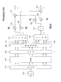
- FIG. 7 schematically shows the architecture of a FS-FBMC receiver according to one alternative of the first embodiment of the invention.
- FIG. 8A schematically shows a first example of transmission of two sequences of blocks of symbols by an FBMC transmitter using a first block Alamouti coding
- FIG. 8B schematically shows a second example of transmission of two sequences of blocks of symbols by an FBMC transmitter using a second block Alamouti coding
- FIG. 9 schematically shows the architecture of an FS-FBMC receiver, according to a second embodiment of the invention, used to receive sequences of blocks transmitted according to the schematic representation in FIG. 8B .
- the elements of these vectors are therefore real value elements.
- the signal transmitted by the transmitter at the instant m can be represented by a column vector Z m of size KN whose elements are samples at a frequency Nf.
- the vector Z m can be expressed as a function of the input data vectors X m ⁇ (K ⁇ 1) , . . . , X m , . . . , X m+(K ⁇ 1) , that is:
- ⁇ is the Hadamard product
- F is the discrete Fourier transform matrix of size KN ⁇ KN
- G is a matrix of size KN ⁇ N representing the spectral spreading and the transfer function of the prototype filter in the frequency domain, that is:
- the signal received by the FBMC receiver at the instant in may similarly be expressed in the form of a data vector at the output of the OQAM demodulator, here referred to as Y m , of size KN.
- the basic idea of the invention is to use a receiver implemented in the frequency domain (FS-FBMC receiver) and to combine the two blocks at the output of the FFT module (module 170 in FIG. 1 ), during the first and second use of the channel respectively.
- X 0 m is the m th input data vector of the first block X 0 and X 1 m the m th input data vector of the second block X 1 respectively.
- W 0 m is the m th sample vector at the output to the FFT module, before de-spreading and filtering, during the first use of the channel.
- W 1 m is the m th sample vector at the output of the FFT module, before de-spreading and filtering, during the second use of the channel.
- FIG. 6 schematically shows the architecture of an FS-FBMC receiver, according to a first embodiment of the invention, used to receive sequences of blocks of symbols coded by a block Alamouti coding.
- the receiver comprises a sampling module 610 for sampling the signal received in a base band at the rate of Nf where N is the number of sub-carriers and f is the frequency of the FBMC symbols.
- the samples are grouped together in the form of blocks of size KN by a serial-parallel converter 620 .
- the receiver is assumed to be synchronised on the FBMC symbols, in other words, the start of an FFT window coincides with the first sample of an FBMC symbol (transmitted by one or the other of the transmission antennae). Moreover, the receiver is assumed to be synchronised on the instants of use of the channel so that it knows the instants at which the first and second blocks are received.
- the blocks of samples undergo a FFT of size KN in the FFT module 630 .
- a demultiplexer 640 supplies the vectors at the output from the FFT at a first output 641 during the first use of the channel and at a second output 642 during the second use of the channel.
- the L vectors (of size KN) generated sequentially at the first output are stored in a first buffer memory 651 , configured in the form of a FIFO (first-in first-out) buffer.
- the L vectors generated sequentially at the second output are also stored in a second buffer memory 652 configured in the form of a LIFO (last-in first-out) buffer.
- the module 660 thus reads the L vectors in the reverse order to that in which they are stored (LIFO), so as to perform a time-reversal and furthermore undertakes a complex conjugation of each of these vectors.
- a multiplier 670 multiplies the elements of the vectors at the output from the module 660 by (j) L ⁇ 1 , in other words by j if L is an even number.
- Each element of a vector generated at the first output is multiplied in 681 by the complex conjugate of the coefficient of the first elementary channel between the first transmission antenna and the reception antenna, at the frequency of the sub-carrier carrying the element in question (the operation is symbolised here by a multiplication of the vector at the output from the buffer memory by the matrix H 0 *) and in 683 by the complex conjugate of the coefficient of the second elementary channel between the second transmission antenna and the reception antenna, at the same sub-carrier frequency (the operation is symbolised here by a multiplication of the vector of samples at the FFT output by the matrix H 1 *).
- the matrices H 0 and H 1 are here meant to be of size KN ⁇ KN and here represent the coefficients of the elementary channels for the KN spectrally spread sub-carriers. An identical channel coefficient can be chosen for the K frequencies produced by a given sub-channel. It is assumed that the matrices H 0 and H 1 are constant over the duration of the sequence (flat fading assumption).
- each element in a vector generated at the second output is multiplied in 682 by the coefficient for the channel between the first transmission antenna and the reception antenna at the frequency of the sub-carrier carrying the element in question (operation symbolised by a multiplication of the vector at the output of the FFT by the matrix H 0 ) and in 684 by the coefficient of the channel between the second transmission antenna and the reception antenna at the frequency of the same sub-carrier (operation symbolised by a multiplication of the vector at the output of the FFT by the matrix H 1 ).
- the vectors at the output of the multiplier 681 are summed, element by element, with those at the output of the multiplier 684 , in the summer 691 .
- the successive vectors of size N at the output of the summer 691 are then supplied to a first spectral de-spreading and filtering module 695 .
- the vectors at the output of the multiplier 682 are subtracted, element by element, from those at the output of the multiplier 683 , in the summer 692 .
- the successive vectors of size N at the output of the summer 692 are then supplied to a second spectral de-spreading and filtering module 696 .
- FIG. 7 schematically shows the architecture of a FS-FBMC receiver according to one alternative of the first embodiment of the invention.
- the receiver here comprises two reception antennas.
- the signal received on the first antenna during the first use of the channel is demodulated into a base band then sampled at a rate Nf in the sampler 711 .
- the samples are grouped together in the form of blocks of size KN by the serial-parallel converter 721 before undergoing a sliding FFT of size KN in 731 .
- the vectors of the samples at the output of the FFT are then processed on a first path.
- the signal received on the second antenna during the second use of the channel is demodulated into a base band then sampled at a rate Nf in the sampler 712 .
- the samples are grouped together in the form of blocks of size KN by the serial-parallel converter 722 before undergoing a sliding FFT of size KN in 732 .
- the vectors of the samples at the output of the FFT are then processed on a second path.
- the remaining elements 751 - 796 are, respectively, identical to elements 651 - 696 of FIG. 6 .
- the structure of the receiver of FIG. 6 or of FIG. 7 can be simplified when the transmitter, instead of using the coding given by (15), uses the block Alamouti coding defined by:
- the multiplication by the factor (j L ⁇ 1 ) can be removed at the reception and consequently the multiplier 670 or 770 can be omitted.
- FIG. 8A schematically shows a first example of the transmission of two sequences of blocks of symbols by an FBMC transmitter using a first block Alamouti coding, as given by the coding matrix given by the expression (15).
- the blocks of data to be transmitted are here considered upstream of the OQAM modulation.
- a first sequence of blocks 801 is formed by a first guard block 811 , a first block of L input data vectors, X 0 , 821 , a second guard block, 831 , followed by a first transformed block, ⁇ X 1 T, 841 , obtained by time-reversal and change of sign of the first input data block.
- a second sequence of blocks 802 is formed by a first guard block 812 , a second block of L input data vectors, X 1 , 822 , a second guard block, 832 , followed by a second transformed block, X 0 T, 842 , obtained by time-reversal and change of sign of the first input data block.
- the guard blocks are made up of null vectors in order to prevent interference between the data blocks and the transformed blocks.
- the first and second sequences are respectively transmitted by the first and second antennas, 892 and 892 , after FBMC modulation.
- FIG. 8B schematically shows a second example of the transmission of two sequences of blocks of symbols by an FBMC transmitter using a second block Alamouti coding.
- the second example is identical to the first except that the first guard block is replaced in the first sequence by a first preamble 811 ′ and in the second by sequence by a second preamble 812 ′.
- the other blocks remain unchanged and are therefore not described again.
- the first and second preambles generate interference which affects the first symbols of the blocks X 0 and X 1 , interference which does not symmetrically affect the blocks ⁇ X 1 T and X 0 T. This asymmetry does not allow the interference for the input data vectors X 0 m , X 1 m at the beginning of the block, to be eliminated.
- the preamble symbols are however known to the receiver and it is possible to eliminate this interference once an estimate of the transmission channel is available.
- FIG. 9 schematically shows the architecture of an FS-FBMC receiver, according to a second embodiment of the invention, used to receive sequences of blocks in FIG. 8B .
- the elements 910 to 996 are identical to the elements 610 to 696 already described in relation to FIG. 6 .
- the interference canceller 945 is located on the first output from the demultiplexer 940 and therefore only operates during the first use of the channel. Its purpose is to eliminate the interference generated at the receiver by the first and second preambles 811 ′ and 812 ′, on the payload X 0 , X 1 . More precisely, the interference canceller receives an estimate of the transmission channel, namely the transfer matrices for the elementary channels H 0 and H 1 .
- the preambles 811 ′ and 812 ′ are known to the receiver, the latter can reconstitute the contribution of the preambles to the signal received during the reception of blocks X o and X 1 , it being understood that only the first K+E vectors received at the beginning of these blocks are affected by this interference, where K is the length of the prototype filter and E the time-spreading of the channel expressing as number of samples.
- K is the length of the prototype filter
- E the time-spreading of the channel expressing as number of samples.
- the contribution of the preambles is subtracted from the received signal at the output of the FFT module 830 .
- the transmitted blocks X 0 and X 1 may be estimated in accordance with (22-1) and (22-1), it being understood once more that the term j L ⁇ 1 may be omitted if the block Alamouti coding defined by (23) is used.
- this second embodiment may also take the form of the alternative in FIG. 7 by adding an interference canceller at the output of the FFT module 731 .
Landscapes
- Engineering & Computer Science (AREA)
- Computer Networks & Wireless Communication (AREA)
- Signal Processing (AREA)
- Radio Transmission System (AREA)
- Physics & Mathematics (AREA)
- Discrete Mathematics (AREA)
- General Physics & Mathematics (AREA)
- Mathematical Physics (AREA)
- Digital Transmission Methods That Use Modulated Carrier Waves (AREA)
Abstract
Description
{hacek over (d)} i,k [n]=d i [n]G k ,k=−K+1, . . . ,0, . . . ,K−1 (1)
Data with the same parity i and i+2 are spectrally separated and data with opposite parities i and i+1 overlap as shown in
wherein x0 and x1 are two complex symbols (belonging to a modulation alphabet) to be transmitted. During a first use of the channel (that is, a first transmission interval) the transmission antennas respectively transmit x0 and x1, and during a second use of the channel these antennas transmit −x1*and x0*.
y 0 =h 0 x 0 +h 1 x 1 +n 0 (4-1)
y 1 =−h 0 x 1 *+h 1 x 0 *+n 1 (4-2)
where h0,h1 are, respectively, the complex coefficient of the first elementary channel between the first transmission antenna and the reception antenna, and the complex coefficient of the second elementary channel between the second transmission antenna and the reception antenna, and where n0,n1 are noise samples, assumed to be additive and independent, from a given centred white Gaussian process.
The block-columns of the block-matrix here represent the antennae and the block-lines represent the uses of the channel. In each of the blocks, the lines represent the sub-carriers and the columns represent the time. T is an anti-diagonal matrix of size L×L all of whose anti-diagonal elements are equal to 1, and thus translates a time reversal. Thus, if
where
{circumflex over (X)} 0 m =μG(H 0 *W 0 m +j L−1 H 1 W 1 L−1−m*)⊙M m*
{circumflex over (X)} 1 m =μG(H 1 *W 0 m −j L−1 H 0 W 1 L−1−m*)⊙M m*
where {circumflex over (X)}0 m and {circumflex over (X)}1 m are respectively the estimates of the vectors X0 m and X1 m, H0, H1 are respectively the first and second transfer matrices, W0 m the vector of rank m received on the first path, W1 L−1−m the vector of rank L−1−m received on the second path, Mm a vector which represents an OQAM coding of vectors X0 m and X1 m, G a matrix which represents, in the frequency domain, a spectral de-spreading and filtering by prototype filters, μ is a coefficient of normalisation and ⊙ represents the Hadamard product.
where
{circumflex over (X)} 0 m =μG(H 0 *W 0 m +H 1 W 1 L−1−m*)⊙M m*
{circumflex over (X)} 1 m =μG(H 1 *W 0 m −H 1 W 1 L−1−m*)⊙M m*
where {circumflex over (X)}0 m and {circumflex over (X)}1 m are respectively the estimates of the vectors X0 m and X1 m, H0, H1 are respectively the first and second transfer matrices, W0 m the vector of rank m received on the first path, W1 L−1−m the vector of rank L−1−m received on the second path, Mm a vector which represents an OQAM coding of vectors X0 m and X1 m, G a matrix which represents, in the frequency domain, a spectral de-spreading and filtering by prototype filters, μ is a coefficient of normalisation and ⊙ represents the Hadamard product.
where ⊙ is the Hadamard product, F is the discrete Fourier transform matrix of size KN×KN, G is a matrix of size KN×N representing the spectral spreading and the transfer function of the prototype filter in the frequency domain, that is:
Mm is a column vector of size N which expresses the OQAM modulation, namely a vector whose elements are given by:
M m [k]=j m+k(−1)km (10)
and Ql is an offset matrix of l samples, of size KN×KN defined by:
where TKN−
Y m=(G H FH 0 Z m)⊙M m* (12)
or, given that GHFFHG=IN and that (Xm ⊙Mm)⊙Mm*=Xm:
an expression in which good use has been made of the fact that the input data vectors were real value vectors.
It will be seen that the transfer matrices for the elementary channels, H0 and H1 are here of size KN×KN due to the spectral spreading.
That is by taking into consideration that:
M L−1−m *=−M m j L−1 ; M L−1−m-p *=−M m+p j L−1 ; M L−1−m+p *=−M m−p j L−1
where it is assumed that the size L of the block was an even number, and that:
A p *=B p ; B p *=A p
the vector W1 L−m−1* of the reversed block can finally be written as:
{hacek over (X)} 0 m=μ(H 0 *W 0 m +j L−1 H 1 W 1 L−1−m*) (21-1)
{hacek over (X)} 1 m=μ(H 1 *W 0 m −j L−1 H 0 W 1 L−1−m*) (21-2)
where
then filtering and spectral de-spreading and finally an OQAM demodulation:
{circumflex over (X)} 0 m =μG(H 0 *W 0 m +j L−1 H 1 W 1 L−1−m*)⊙M m* (22-1)
{circumflex over (X)} 1 m =μG(H 1 *W 0 m −j L−1 H 0 W 1 L−1−m*)⊙M m* (22-2)
Claims (9)
{circumflex over (X)} 0 m =μG(H 0 *W 0 m +j L−1 H 1 W 1 L−1−m*)⊙M m*
{circumflex over (X)} 1 m =μG(H 1 *W 0 m −j L−1 H 0 W 1 L−1−m*)⊙M m*
{circumflex over (X)} 0 m =μG(H 0 *W 0 m +H 1 W 1 L−1−m*)⊙M m*
{circumflex over (X)} 1 m =μG(H 1 *W 0 m −H 1 W 1 L−1−m*)⊙M m*
Applications Claiming Priority (2)
| Application Number | Priority Date | Filing Date | Title |
|---|---|---|---|
| FR1653277A FR3050345B1 (en) | 2016-04-13 | 2016-04-13 | RECEIVER FOR FBMC SYSTEM WITH BLOCKED ALUMINUM TYPE SPATIO-TEMPORAL ENCODING |
| FR1653277 | 2016-04-13 |
Publications (2)
| Publication Number | Publication Date |
|---|---|
| US20170310527A1 US20170310527A1 (en) | 2017-10-26 |
| US9893926B2 true US9893926B2 (en) | 2018-02-13 |
Family
ID=56611343
Family Applications (1)
| Application Number | Title | Priority Date | Filing Date |
|---|---|---|---|
| US15/485,723 Active US9893926B2 (en) | 2016-04-13 | 2017-04-12 | Receiver for alamouti type space-time block coding FBMC system |
Country Status (3)
| Country | Link |
|---|---|
| US (1) | US9893926B2 (en) |
| EP (1) | EP3232627B1 (en) |
| FR (1) | FR3050345B1 (en) |
Families Citing this family (2)
| Publication number | Priority date | Publication date | Assignee | Title |
|---|---|---|---|---|
| EP3206353B1 (en) * | 2016-02-09 | 2020-02-05 | Technische Universität München | Filter banks and methods for operating filter banks |
| CN114039822B (en) * | 2021-11-11 | 2023-10-03 | 成都中科微信息技术研究院有限公司 | Channel estimation method and system for short packet burst communication system |
Citations (9)
| Publication number | Priority date | Publication date | Assignee | Title |
|---|---|---|---|---|
| US20140348252A1 (en) | 2011-12-23 | 2014-11-27 | Orange | Method for transmitting at least one multi-carrier signal consisting of ofdm-oqam symbols |
| US20150009906A1 (en) | 2013-07-03 | 2015-01-08 | Commissariat A L'energie Atomique Et Aux Ene Alt | Multiple access method and system with frequency multiplexing of requests for authorisation to send data |
| US20150124749A1 (en) | 2013-11-06 | 2015-05-07 | Commissariat A L'energie Atomique Et Aux Ene Alt | Multiple access method and system with frequency multiplexing of several request to send messages per source node |
| US20160013961A1 (en) * | 2013-03-13 | 2016-01-14 | Commissariat A L'energie Atomique Et Aux Energies Alternatives | Fbmc receiver using a method for synchronization in a frequency domain |
| US20160301554A1 (en) | 2015-04-10 | 2016-10-13 | Commissariat A L'energie Atomique Et Aux Energies Alternatives | Receiver and fbmc reception method with low decoding latency |
| US20170012808A1 (en) | 2015-07-09 | 2017-01-12 | Commissariat A L'Energie Atomiqe et aux Energies Alternatives | Very high bit rate rfid receiver |
| US20170012676A1 (en) | 2015-07-09 | 2017-01-12 | Commissariat A L'energie Atomique Et Aux Energies Alternatives | Quadrature demodulator for a very high bit rate rfid receiver |
| US20170019223A1 (en) | 2015-07-17 | 2017-01-19 | Commissariat A L'energie Atomique Et Aux Energies Alternatives | Multiple access method and system with adaptive frequency multiplexing of data send authorization requests |
| US20170085308A1 (en) * | 2015-08-21 | 2017-03-23 | Samsung Electronics Co., Ltd | Method and apparatus for transmitting diversity |
-
2016
- 2016-04-13 FR FR1653277A patent/FR3050345B1/en not_active Expired - Fee Related
-
2017
- 2017-04-12 US US15/485,723 patent/US9893926B2/en active Active
- 2017-04-12 EP EP17166149.9A patent/EP3232627B1/en active Active
Patent Citations (9)
| Publication number | Priority date | Publication date | Assignee | Title |
|---|---|---|---|---|
| US20140348252A1 (en) | 2011-12-23 | 2014-11-27 | Orange | Method for transmitting at least one multi-carrier signal consisting of ofdm-oqam symbols |
| US20160013961A1 (en) * | 2013-03-13 | 2016-01-14 | Commissariat A L'energie Atomique Et Aux Energies Alternatives | Fbmc receiver using a method for synchronization in a frequency domain |
| US20150009906A1 (en) | 2013-07-03 | 2015-01-08 | Commissariat A L'energie Atomique Et Aux Ene Alt | Multiple access method and system with frequency multiplexing of requests for authorisation to send data |
| US20150124749A1 (en) | 2013-11-06 | 2015-05-07 | Commissariat A L'energie Atomique Et Aux Ene Alt | Multiple access method and system with frequency multiplexing of several request to send messages per source node |
| US20160301554A1 (en) | 2015-04-10 | 2016-10-13 | Commissariat A L'energie Atomique Et Aux Energies Alternatives | Receiver and fbmc reception method with low decoding latency |
| US20170012808A1 (en) | 2015-07-09 | 2017-01-12 | Commissariat A L'Energie Atomiqe et aux Energies Alternatives | Very high bit rate rfid receiver |
| US20170012676A1 (en) | 2015-07-09 | 2017-01-12 | Commissariat A L'energie Atomique Et Aux Energies Alternatives | Quadrature demodulator for a very high bit rate rfid receiver |
| US20170019223A1 (en) | 2015-07-17 | 2017-01-19 | Commissariat A L'energie Atomique Et Aux Energies Alternatives | Multiple access method and system with adaptive frequency multiplexing of data send authorization requests |
| US20170085308A1 (en) * | 2015-08-21 | 2017-03-23 | Samsung Electronics Co., Ltd | Method and apparatus for transmitting diversity |
Non-Patent Citations (12)
| Title |
|---|
| Botaro Hirosaki, "An Orthogonally Multiplexed QAM System Using the Discrete Fourier Transform", IEEE Transactions on Communications, vol. COM-29, (7), 1981, 8 pgs. |
| Erik Lindskog, et al., "A Transmit Diversity Scheme for Channels with Intersymbol Interference", IEEE, 2000, 5 pgs. |
| French Preliminary Search Report dated Dec. 1, 2016 in French Application 16 53277 filed on Apr. 13, 2016 (with English Translation of Categories of Cited Documents). |
| Le et al., "On the Performance of Alamouti Scheme in 2 x 2 MIMO-FBMC Systems," Aug. 2016, 19th International Conference on OFDM and Frequency Domain Techniques (ICOF 2016), pp. 28-33. * |
| M. Bellanger, et al., "FBMC physical layer: a primer", PHYDYAS, 2010, 31 pgs. |
| Markku Renfors, et al., "A Block-Alamouti Scheme for Filter Bank Based Multicarrier Transmission", European Wireless Conference, IEEE, 2010, 7 pgs. |
| Maurice Bellanger, "FS-FBMC: an alternative scheme for filter bank based multicarrier transmission", Proceedings of the 5th International Symposium on Communications, Control and Signal Processing, IEEE, 2012, 4 pgs. |
| Na et al., "Intrinsic ICI-Free Alamouti Coded FBMC," Jul. 2016, IEEE Communications Letters, vol. 20, Issue 10, pp. 1971-1974. * |
| Pierre Siohan, et al., "Analysis and Design of OFDM/OQAM Systems Based on Filterbank Theory", IEEE Transactions on Signal Processing, vol. 50, (5), 2002, 14 pgs. |
| R. Zakaria, et al., "On interference cancellation in Alamouti coding scheme for filter bank based multicarrier systems", The Tenth International Symposium on Wireless Communication Systems, 2013, 5 pgs. |
| U.S. Appl. No. 15/485,700, filed Apr. 12, 2017, Jean-Baptiste Dore. |
| Zakaria et al., "A Novel Filter-Bank Multicarrier Scheme to Mitigate the Intrinsic Interference: Application to MIMO Systems," Mar. 2012, IEEE Transactions on Wireless Communications, vol. 11, Issue 3, pp. 1112-1123. * |
Also Published As
| Publication number | Publication date |
|---|---|
| FR3050345B1 (en) | 2018-04-13 |
| US20170310527A1 (en) | 2017-10-26 |
| EP3232627A1 (en) | 2017-10-18 |
| FR3050345A1 (en) | 2017-10-20 |
| EP3232627B1 (en) | 2021-03-10 |
Similar Documents
| Publication | Publication Date | Title |
|---|---|---|
| US9167579B2 (en) | Method and transmitter/receiver for data transmission with flexible exploitation of time and frequency diversity | |
| DE60223367T2 (en) | A method for transmitting from a base station of an MC-CDMA telecommunication system to a plurality of users | |
| US6317409B1 (en) | Residue division multiplexing system and apparatus for discrete-time signals | |
| Bellanger et al. | FBMC physical layer: a primer | |
| AU725718B2 (en) | Pulse shaping for multicarrier modulation | |
| CN101682454B (en) | Method for transmitting and receiving a multicarrier spread-spectrum signal and corresponding signal, and transmission and reception devices | |
| US9967060B2 (en) | Transmitter for FBMC system with block-alamouti type space-time coding | |
| KR20060102185A (en) | Transmission and reception apparatus and method using frequency space block coding technique and single carrier frequency domain equalization | |
| US9893926B2 (en) | Receiver for alamouti type space-time block coding FBMC system | |
| CN101267415B (en) | Flexible uplink multi-address transmission device based on filter group and its method | |
| Nimr et al. | Generalized frequency division multiplexing: Unified multicarrier framework | |
| EP3244547B1 (en) | Mimo-fbmc transmitter/receiver with linear precoding implemented in the frequency domain | |
| US11108600B2 (en) | Systems and methods for time domain layer separation in orthogonal frequency division multiplexing-based receivers | |
| EP3032791B1 (en) | Orthogonal multicarrier transmission system using conjugate-root offset-QAM | |
| US20020181562A1 (en) | Equalisation method and device of the GMMSE type | |
| US9893923B2 (en) | Method for transmitting and receiving QAM signal in filter bank-based multicarrier communication system, and apparatus therefor | |
| CN101335551B (en) | SINR estimation method based on multi-antenna diversity scheme of DFT-S-GMC system | |
| Raslan et al. | Performance Analysis of Emerging Waveforms for 6G Wireless Communications | |
| Sinn et al. | Common architectures for TD-CDMA and OFDM based mobile radio systems without the necessity of a cyclic prefix | |
| EP3032790A1 (en) | Generalized frequency division multiplexing radio transmission using frequency domain Offset-QAM | |
| Oh et al. | The bandwidth efficiency increasing method of multi-carrier CDMA and its performance evaluation in comparison with DS-CDMA with RAKE receivers | |
| CN109347773B (en) | Receiver design method for multi-user uplink generalized frequency division multiple access system | |
| KR100230607B1 (en) | Time-domain detection method for the mc-cdma system | |
| KR101019172B1 (en) | Apparatus and method for transmitting / receiving data in a communication system using U-BSLAT OPM system | |
| Bellanger | THE POTENTIAL OF OQAM FOR MULTICARRIER RADIOCOMMUNICATIONS |
Legal Events
| Date | Code | Title | Description |
|---|---|---|---|
| AS | Assignment |
Owner name: COMMISSARIAT A L'ENERGIE ATOMIQUE ET AUX ENERGIES Free format text: ASSIGNMENT OF ASSIGNORS INTEREST;ASSIGNOR:DORE, JEAN-BAPTISTE;REEL/FRAME:043307/0021 Effective date: 20170706 |
|
| STCF | Information on status: patent grant |
Free format text: PATENTED CASE |
|
| MAFP | Maintenance fee payment |
Free format text: PAYMENT OF MAINTENANCE FEE, 4TH YEAR, LARGE ENTITY (ORIGINAL EVENT CODE: M1551); ENTITY STATUS OF PATENT OWNER: LARGE ENTITY Year of fee payment: 4 |
|
| MAFP | Maintenance fee payment |
Free format text: PAYMENT OF MAINTENANCE FEE, 8TH YEAR, LARGE ENTITY (ORIGINAL EVENT CODE: M1552); ENTITY STATUS OF PATENT OWNER: LARGE ENTITY Year of fee payment: 8 |