US989357A - Feed-water regulator. - Google Patents
Feed-water regulator. Download PDFInfo
- Publication number
- US989357A US989357A US55810010A US1910558100A US989357A US 989357 A US989357 A US 989357A US 55810010 A US55810010 A US 55810010A US 1910558100 A US1910558100 A US 1910558100A US 989357 A US989357 A US 989357A
- Authority
- US
- United States
- Prior art keywords
- valve
- tube
- case
- arm
- lever
- Prior art date
- Legal status (The legal status is an assumption and is not a legal conclusion. Google has not performed a legal analysis and makes no representation as to the accuracy of the status listed.)
- Expired - Lifetime
Links
- XLYOFNOQVPJJNP-UHFFFAOYSA-N water Substances O XLYOFNOQVPJJNP-UHFFFAOYSA-N 0.000 title description 40
- 230000008602 contraction Effects 0.000 description 3
- 239000002184 metal Substances 0.000 description 2
- 229940000425 combination drug Drugs 0.000 description 1
- 230000005494 condensation Effects 0.000 description 1
- 238000009833 condensation Methods 0.000 description 1
- 238000010276 construction Methods 0.000 description 1
- 238000009434 installation Methods 0.000 description 1
Images
Classifications
-
- F—MECHANICAL ENGINEERING; LIGHTING; HEATING; WEAPONS; BLASTING
- F22—STEAM GENERATION
- F22D—PREHEATING, OR ACCUMULATING PREHEATED, FEED-WATER FOR STEAM GENERATION; FEED-WATER SUPPLY FOR STEAM GENERATION; CONTROLLING WATER LEVEL FOR STEAM GENERATION; AUXILIARY DEVICES FOR PROMOTING WATER CIRCULATION WITHIN STEAM BOILERS
- F22D5/00—Controlling water feed or water level; Automatic water feeding or water-level regulators
- F22D5/14—Controlling water feed or water level; Automatic water feeding or water-level regulators responsive to thermal expansion and contraction, e.g. of solid elements
Definitions
- the object of this invention is the construction of a self contained feed water regulator, wherein all parts are attached and assembled in a simple and compact form, so that when it is shipped to the purchaser it will only be necessary to make the needed connections to the boiler and to the feed water supply, which can readily be done, no other attaching of parts being necessary.
- the means employed are, a perfectly balanced valve placed intermediate the water supply and the boiler, and a tube of highly expansible metal with a connection to the normal water line of the boiler, another connection to the body of water in the boiler, and a combination of means whereby the expansion of the tube opens the valve and its contraction closes the valve.
- the apparatus is placed somewhat above the body of water, so that only dry steam can enter the expansion tube.
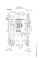
- Figure 1 is an elevation view, some parts being in section.
- Fig. 2 is a top or plan view.
- Figs. 3, 4 are end views.
- Fig. 5 is an end view of the fulcrum links.
- Fig. 6 is a top view of Fig. 5.
- a valve 1 and its seat 2 are inclosed in an outer casing 3 which is placed in the feed water line, with a pipe connection 4 leading from the source of water supply, and a pipe 5 leading to the water space of the boiler.
- the valve illustrated is one of the preferred forms, that is, a balanced valve, and in the illustration shown is of cylindrical form, adapted for upward movement to open ports 6 1n its seat 2 and permit the flow from pipe 4 to pipe 5, and for downward movement to stop the flow.
- Case 3 has a cover 7 on which is mounted a stand having arms 8, 9.
- Arm 8 has an upward extension 10 with a hub 11 into which is screwed steam pipe 12 which is secured to the boiler just below its normal water line, so that when the normal level is maintained the orifice of pipe 12 will admit water into the pipe.
- a plug 16 stops the opposite side of head 14.
- Head 14 has a jaw 17 to which is secured the vertical end of bell crank valve lever 18 by a pin 19, and below pin 19 the lever is secured to the upper end of the twin fulcrum links 20 by a pin 21.
- lever 18 From pin 21 lever 18 is bent at a right angle from where it is attached to head 14 and links 20, and passes toward and beyond the valve, between expansion tube 13 and arms 8, 9 and has adjustably attached thereto a rod or valve stem 22 which passes through stuifing box 23 and is attached to and operates valve 1.
- a counterweight 24 on lever 18 closes valve 1 at such times as it is not in use.
- twin fulcrum links 20' are secured to arm 9 by a pin 25, and they have a connection 26 against which a screw 27 in hub 28 of the upright part 29 of arm 9, operates to move the horizontal arm of lever 18 up or down, to regulate valve 1 to a desired posi tion in its seat 2.
- a tie rod 30, as part of the framework, is attached to lug 31 of hub 11 and boss 32 of upright 29.
- a pulley 33 may be attached at any convenient place above the apparatus, and a cord 34 attached to lever 18, passed over the pulley and down to a convenient position.
- the expansion tube 13 is elevated at a distance above the water line which will insure it from receiving anything but steam.
- the pipe 12 has its orifice enough below the fixed normal water line to insure a Water seal.
- the tube being of high expansive power is elongated by the heat of the steam, and head 14 using pin 21 as a fulcrum moves up the long arm of the bell crank lever 18 and the attached valve stem or rod 22, and valve 1 to admit the flow from pipe 4: through ports 6 to pipe 5 and the boiler.
- a balanced valve adapted to intercept the feed water to a boiler, a case for the valve, pipes leading to and from the case, a stand mounted upon the case and having oppositely reaching arms, an expansion tube, having one end rigidly attached to an arm of the stand and having a connection to the desired water level of a boiler, a free end for the tube, and having a support upon the opposite arm of the stand, a connection from the free end of the tube to the water space of a boiler, and a bell crank lever interposed between the expansion tubes free end and the valve, with a connection to the tube, and to the valve, and whereby the expansion tube controls the valve.
- a balanced valve a case for the valve, a. water inlet to the case, a water outlet from the case to a boiler, a stand secured to the case at its upper part and provided with outwardly extending and upwardly reaching arms; an expansible tube, a rigid support for the tube upon one arm, and a pivotal support for the tube upon the opposite arm; a bell crank lever, a pivotal connection from the short end of the lever to the free end of .the expansion tube, a pivotal support for the lever, on the arm, and a direct connection from the long end of the lever to the valve.
- a feed water regulator In a feed water regulator, .the combi nation of a feed water valve, and a. case therefor, feed water pipe to and from the case, a stand mounted upon the case and having oppositely extending and upwardly reaching arms, an expansion tube rigidly fixed to one arm and having a connection to a boiler, the opposite end of the tube having a support upon the opposite arm, and having a drainage connection; and a bell crank lever operatively connected to the expansible tube and to the valve, and whereby the expansion of the tube opens the valve, and its contraction closes the valve.
- case for the valve a feed water line to the case, and from the case to a boiler, a stand mounted upon the case, an arm extending from the stand, an expansion tube, means to rigidly secure the tube to the arm in practically a horizontal position and above the valve case, a connection from the tube to a boiler, the opposite end of the tube being free and having a drainage connection to the boiler; an opposite arm for the stand, a bell crank having a minor arm, and a pivotal connection from the bell crank arm to the free end of the expansion tube, a major arm for the bell crank extending under the tube, with a connection to the valve, and a pivotal support for the minor end of the bell crank and whereby the major end of the bell crank is made to move upward as the tube expands, and downward as the tube contracts.
- a feed water regulator the combination with a feed water valve, a case for the valve, and supply and delivery pipes there for, of a stand mounted on the valve case, an expansible tube having a rigid support at one portion of the stand, a bell crank lever pivotally attached to the opposite or free end of the tube, fulcrum links pivotally attached to the bell crank lever and pivotally supported upon the stand, a rod connecting the valve and the bell crank lever, and adjustable means whereby the fulcrum links may be made to raise and lower the bell crank lever at its connection with the valve rod, for the adjustment of the valve.
- a feed water regulator the combination of a feed water valve, a case for the valve, feed water pipes to the case and from the case to a boiler, a stand mounted upon the valve case, an expansion tube, means for rigidly supporting one end of the tube upon the stand, a free end for the tube, a bell crank lever with unequal arms, a pivotal connection from the short arm of the lever to the free end of the tube twin fulcrum links pivotally connecting the short arm of the lever and the stand; the long arm of the lever having a connection with the valve, a counterweight to close the valve, and adj ustable means operative upon the twin fulcrum links to raise and lower the long arm of the lever at its valve connection.
- a feed water regulator the combination of a feed water valve, a case for the valve, entrance and exit pipes for the case, a hand to open the valve, and means to adstand carried by the valve case, an eXpansijust the twin fulcrum links to raise or lower ble tube rigidly attached by one end to the the bell crank lever at its valve connection, stand, afree end for the tube, a bell crank for the adjustment of the valve.
Landscapes
- Engineering & Computer Science (AREA)
- Physics & Mathematics (AREA)
- Thermal Sciences (AREA)
- Mechanical Engineering (AREA)
- General Engineering & Computer Science (AREA)
- Mechanically-Actuated Valves (AREA)
Description
H. E. HEISLEY. FEED WATER REGULATOR. APPLICATION FILED APR. 28, 1910.
Patented Apr. 11, 1911.
JnUcmfor. Hang Ely: ASL-g 0% THE mamas PETERS co, wnsmncmrv, n, c.
HENRY E. HEISLEY, OF PHILADELPHIA, PENNSYLVANIA, ASSIGNOB 0F ONE-HALF T0 CHARLES G. WILFONG, OF PHILADELPHIA, PENNSYLVANIA.
FEED-WATER REGULATOR.
Specification of Letters Patent.
Patented Apr. 11, 1911.
To all whom it may concern:
Be it known that I, HENRY E. HmsLEr, a citizen of the United States, residing at Philadelphia, in the county of Philadelphia and State of Pennsylvania, have invented certain new and useful Improvements in Feed-Water Regulators, of which the following is a specification.
The object of this invention is the construction of a self contained feed water regulator, wherein all parts are attached and assembled in a simple and compact form, so that when it is shipped to the purchaser it will only be necessary to make the needed connections to the boiler and to the feed water supply, which can readily be done, no other attaching of parts being necessary. The means employed are, a perfectly balanced valve placed intermediate the water supply and the boiler, and a tube of highly expansible metal with a connection to the normal water line of the boiler, another connection to the body of water in the boiler, and a combination of means whereby the expansion of the tube opens the valve and its contraction closes the valve. The apparatus is placed somewhat above the body of water, so that only dry steam can enter the expansion tube.
The accompanying drawing, in which similar figures of reference indicate the same parts, throughout the several views, illustrates the means employed, in which,
Figure 1 is an elevation view, some parts being in section. Fig. 2 is a top or plan view. Figs. 3, 4 are end views. Fig. 5 is an end view of the fulcrum links. Fig. 6 is a top view of Fig. 5.
A valve 1 and its seat 2 are inclosed in an outer casing 3 which is placed in the feed water line, with a pipe connection 4 leading from the source of water supply, and a pipe 5 leading to the water space of the boiler. As the means for supplying the feed water, and the forms of boilers which the apparatus is adapted to cooperate with are of many and varied forms, which is well understood, it is deemed unnecessary to illustrate them in connection with this appliance. The valve illustrated is one of the preferred forms, that is, a balanced valve, and in the illustration shown is of cylindrical form, adapted for upward movement to open ports 6 1n its seat 2 and permit the flow from pipe 4 to pipe 5, and for downward movement to stop the flow.
Case 3 has a cover 7 on which is mounted a stand having arms 8, 9. Arm 8 has an upward extension 10 with a hub 11 into which is screwed steam pipe 12 which is secured to the boiler just below its normal water line, so that when the normal level is maintained the orifice of pipe 12 will admit water into the pipe. Opposite pipe 12 there is screw threaded into hub 11 an expansion tube 13, of metal of great expansibility, the opposite end of the tube being screw threaded to a head 14 tapped right and left so that a drain pipe 15 may be attached to the head as most convenient, and run to the boilers water space. A plug 16 stops the opposite side of head 14. Head 14 has a jaw 17 to which is secured the vertical end of bell crank valve lever 18 by a pin 19, and below pin 19 the lever is secured to the upper end of the twin fulcrum links 20 by a pin 21. From pin 21 lever 18 is bent at a right angle from where it is attached to head 14 and links 20, and passes toward and beyond the valve, between expansion tube 13 and arms 8, 9 and has adjustably attached thereto a rod or valve stem 22 which passes through stuifing box 23 and is attached to and operates valve 1. A counterweight 24 on lever 18 closes valve 1 at such times as it is not in use.
The twin fulcrum links 20' are secured to arm 9 by a pin 25, and they have a connection 26 against which a screw 27 in hub 28 of the upright part 29 of arm 9, operates to move the horizontal arm of lever 18 up or down, to regulate valve 1 to a desired posi tion in its seat 2.
A tie rod 30, as part of the framework, is attached to lug 31 of hub 11 and boss 32 of upright 29.
In order to open valve 1 by hand a pulley 33 may be attached at any convenient place above the apparatus, and a cord 34 attached to lever 18, passed over the pulley and down to a convenient position.
As furnished to the purchaser or user, this is a complete appliance. already assembled; it is only necessary at the place of application to attach pipes 4, 5, 12, 15 which is readily done, thus avoiding complications, high skilled labor, and the annoyances incident to the installation of detached parts, as heretofore necessary.
In operation, the expansion tube 13 is elevated at a distance above the water line which will insure it from receiving anything but steam. The pipe 12 has its orifice enough below the fixed normal water line to insure a Water seal. As the water line recedes pipe 12 receives steam and conveys it to the expansion tube 13 which is iminovably attached to hub 11. The tube being of high expansive power is elongated by the heat of the steam, and head 14 using pin 21 as a fulcrum moves up the long arm of the bell crank lever 18 and the attached valve stem or rod 22, and valve 1 to admit the flow from pipe 4: through ports 6 to pipe 5 and the boiler. As the desired water level is reached pipe 12 sealed, the steam in tube condenses and the condensation passes to the boiler through pipe 15, the tube 13 contracts and the reverse movements of the parts, as already de scribed closes valve 1. Even with but a slight expansion or contraction of tube 13 the operation of the mechanism is very sensitive, owing to the relative distances between pins 19, 21 and pin 91 and rod or stem 22, or the great leve age, and the adjustment of the valve can be arranged to any desired extent by the operation of screw 37 on connect-ion or tie 26 of the twin fulcrum links 20.
I claim 1. In a feed water regulator, in combination, a balanced valve adapted to intercept the feed water to a boiler, a case for the valve, pipes leading to and from the case, a stand mounted upon the case and having oppositely reaching arms, an expansion tube, having one end rigidly attached to an arm of the stand and having a connection to the desired water level of a boiler, a free end for the tube, and having a support upon the opposite arm of the stand, a connection from the free end of the tube to the water space of a boiler, and a bell crank lever interposed between the expansion tubes free end and the valve, with a connection to the tube, and to the valve, and whereby the expansion tube controls the valve.
2. In a feed water regulator, a balanced valve, a case for the valve, a. water inlet to the case, a water outlet from the case to a boiler, a stand secured to the case at its upper part and provided with outwardly extending and upwardly reaching arms; an expansible tube, a rigid support for the tube upon one arm, and a pivotal support for the tube upon the opposite arm; a bell crank lever, a pivotal connection from the short end of the lever to the free end of .the expansion tube, a pivotal support for the lever, on the arm, and a direct connection from the long end of the lever to the valve.
3. In a feed water regulator, .the combi nation of a feed water valve, and a. case therefor, feed water pipe to and from the case, a stand mounted upon the case and having oppositely extending and upwardly reaching arms, an expansion tube rigidly fixed to one arm and having a connection to a boiler, the opposite end of the tube having a support upon the opposite arm, and having a drainage connection; and a bell crank lever operatively connected to the expansible tube and to the valve, and whereby the expansion of the tube opens the valve, and its contraction closes the valve.
4;. In a feed water regulator, a valve, a
case for the valve, a feed water line to the case, and from the case to a boiler, a stand mounted upon the case, an arm extending from the stand, an expansion tube, means to rigidly secure the tube to the arm in practically a horizontal position and above the valve case, a connection from the tube to a boiler, the opposite end of the tube being free and having a drainage connection to the boiler; an opposite arm for the stand, a bell crank having a minor arm, and a pivotal connection from the bell crank arm to the free end of the expansion tube, a major arm for the bell crank extending under the tube, with a connection to the valve, and a pivotal support for the minor end of the bell crank and whereby the major end of the bell crank is made to move upward as the tube expands, and downward as the tube contracts.
5. In a feed water regulator, the combination with a feed water valve, a case for the valve, and supply and delivery pipes there for, of a stand mounted on the valve case, an expansible tube having a rigid support at one portion of the stand, a bell crank lever pivotally attached to the opposite or free end of the tube, fulcrum links pivotally attached to the bell crank lever and pivotally supported upon the stand, a rod connecting the valve and the bell crank lever, and adjustable means whereby the fulcrum links may be made to raise and lower the bell crank lever at its connection with the valve rod, for the adjustment of the valve.
6. In a feed water regulator, the combination of a feed water valve, a case for the valve, feed water pipes to the case and from the case to a boiler, a stand mounted upon the valve case, an expansion tube, means for rigidly supporting one end of the tube upon the stand, a free end for the tube, a bell crank lever with unequal arms, a pivotal connection from the short arm of the lever to the free end of the tube twin fulcrum links pivotally connecting the short arm of the lever and the stand; the long arm of the lever having a connection with the valve, a counterweight to close the valve, and adj ustable means operative upon the twin fulcrum links to raise and lower the long arm of the lever at its valve connection.
7. In a feed water regulator, the combination of a feed water valve, a case for the valve, entrance and exit pipes for the case, a hand to open the valve, and means to adstand carried by the valve case, an eXpansijust the twin fulcrum links to raise or lower ble tube rigidly attached by one end to the the bell crank lever at its valve connection, stand, afree end for the tube, a bell crank for the adjustment of the valve.
5 lever pivotally attached thereto, twin ful- In testimony whereof I aiiix my signature 15 cruln links pivotally attached to the stand in presence of two witnesses. and to the bell crank lever, a connection HENRY E. HEISLEY. from the bell crank lever to the valve, a Witnesses: counterweight for the bell crank lever, B. C. WRIGHT,
10 means for raising the bell crank lever by WILLIAM C. S'ronvnn.
Copies of this patent may be obtained for five cents each, by addressing the Commissioner of Patents, Washington, D. G.
Priority Applications (1)
| Application Number | Priority Date | Filing Date | Title |
|---|---|---|---|
| US55810010A US989357A (en) | 1910-04-28 | 1910-04-28 | Feed-water regulator. |
Applications Claiming Priority (1)
| Application Number | Priority Date | Filing Date | Title |
|---|---|---|---|
| US55810010A US989357A (en) | 1910-04-28 | 1910-04-28 | Feed-water regulator. |
Publications (1)
| Publication Number | Publication Date |
|---|---|
| US989357A true US989357A (en) | 1911-04-11 |
Family
ID=3057695
Family Applications (1)
| Application Number | Title | Priority Date | Filing Date |
|---|---|---|---|
| US55810010A Expired - Lifetime US989357A (en) | 1910-04-28 | 1910-04-28 | Feed-water regulator. |
Country Status (1)
| Country | Link |
|---|---|
| US (1) | US989357A (en) |
-
1910
- 1910-04-28 US US55810010A patent/US989357A/en not_active Expired - Lifetime
Similar Documents
| Publication | Publication Date | Title |
|---|---|---|
| US604622A (en) | -tared c | |
| US989357A (en) | Feed-water regulator. | |
| US1075043A (en) | Automatic boiler-feed regulator. | |
| US383950A (en) | Dam per-regulator | |
| US1013463A (en) | Automatic cut-off for boiler-feeders. | |
| US630090A (en) | Steam-trap. | |
| US1198836A (en) | Fluid-pressure pump. | |
| US818525A (en) | Water-level regulator. | |
| US246468A (en) | Steam-pressure regulator | |
| US805396A (en) | Gas-pressure regulator. | |
| US113843A (en) | Improvement in low-water indicators | |
| US771686A (en) | Steam-trap. | |
| US819078A (en) | Feed-water regulator. | |
| US1085092A (en) | Self-regulating water-feeder for boilers. | |
| US363307A (en) | Clarence l | |
| US497295A (en) | acton | |
| US630043A (en) | Automatic trap and pump-regulator. | |
| US1046215A (en) | Automatic water-regulator for heaters. | |
| US354121A (en) | Mercurial regulator for dampers | |
| US686413A (en) | Feed-water regulator. | |
| US507077A (en) | William h | |
| US1032176A (en) | Damper-regulator. | |
| US387552A (en) | britts | |
| US860413A (en) | Damper-regulator. | |
| US87181A (en) | Improvement in low-water detectors for steam-generators |