US989068A - Windmill. - Google Patents
Windmill. Download PDFInfo
- Publication number
- US989068A US989068A US58579210A US1910585792A US989068A US 989068 A US989068 A US 989068A US 58579210 A US58579210 A US 58579210A US 1910585792 A US1910585792 A US 1910585792A US 989068 A US989068 A US 989068A
- Authority
- US
- United States
- Prior art keywords
- lever
- sleeve
- blades
- shaft
- windwheel
- Prior art date
- Legal status (The legal status is an assumption and is not a legal conclusion. Google has not performed a legal analysis and makes no representation as to the accuracy of the status listed.)
- Expired - Lifetime
Links
- 239000011435 rock Substances 0.000 description 4
- XLYOFNOQVPJJNP-UHFFFAOYSA-N water Substances O XLYOFNOQVPJJNP-UHFFFAOYSA-N 0.000 description 3
- 230000004075 alteration Effects 0.000 description 2
- 238000010276 construction Methods 0.000 description 2
- 102100026933 Myelin-associated neurite-outgrowth inhibitor Human genes 0.000 description 1
- 238000005266 casting Methods 0.000 description 1
- 210000003414 extremity Anatomy 0.000 description 1
- 238000005086 pumping Methods 0.000 description 1
- 210000003813 thumb Anatomy 0.000 description 1
Images


Classifications
-
- F—MECHANICAL ENGINEERING; LIGHTING; HEATING; WEAPONS; BLASTING
- F03—MACHINES OR ENGINES FOR LIQUIDS; WIND, SPRING, OR WEIGHT MOTORS; PRODUCING MECHANICAL POWER OR A REACTIVE PROPULSIVE THRUST, NOT OTHERWISE PROVIDED FOR
- F03D—WIND MOTORS
- F03D7/00—Controlling wind motors
- F03D7/02—Controlling wind motors the wind motors having rotation axis substantially parallel to the air flow entering the rotor
- F03D7/022—Adjusting aerodynamic properties of the blades
-
- B—PERFORMING OPERATIONS; TRANSPORTING
- B64—AIRCRAFT; AVIATION; COSMONAUTICS
- B64C—AEROPLANES; HELICOPTERS
- B64C11/00—Propellers, e.g. of ducted type; Features common to propellers and rotors for rotorcraft
- B64C11/30—Blade pitch-changing mechanisms
- B64C11/32—Blade pitch-changing mechanisms mechanical
- B64C11/36—Blade pitch-changing mechanisms mechanical non-automatic
-
- F—MECHANICAL ENGINEERING; LIGHTING; HEATING; WEAPONS; BLASTING
- F03—MACHINES OR ENGINES FOR LIQUIDS; WIND, SPRING, OR WEIGHT MOTORS; PRODUCING MECHANICAL POWER OR A REACTIVE PROPULSIVE THRUST, NOT OTHERWISE PROVIDED FOR
- F03D—WIND MOTORS
- F03D9/00—Adaptations of wind motors for special use; Combinations of wind motors with apparatus driven thereby; Wind motors specially adapted for installation in particular locations
- F03D9/20—Wind motors characterised by the driven apparatus
- F03D9/28—Wind motors characterised by the driven apparatus the apparatus being a pump or a compressor
-
- Y—GENERAL TAGGING OF NEW TECHNOLOGICAL DEVELOPMENTS; GENERAL TAGGING OF CROSS-SECTIONAL TECHNOLOGIES SPANNING OVER SEVERAL SECTIONS OF THE IPC; TECHNICAL SUBJECTS COVERED BY FORMER USPC CROSS-REFERENCE ART COLLECTIONS [XRACs] AND DIGESTS
- Y02—TECHNOLOGIES OR APPLICATIONS FOR MITIGATION OR ADAPTATION AGAINST CLIMATE CHANGE
- Y02E—REDUCTION OF GREENHOUSE GAS [GHG] EMISSIONS, RELATED TO ENERGY GENERATION, TRANSMISSION OR DISTRIBUTION
- Y02E10/00—Energy generation through renewable energy sources
- Y02E10/70—Wind energy
- Y02E10/72—Wind turbines with rotation axis in wind direction
Definitions
- This invention belongs to the art of windmills, and it particularly pertains to a device of this design which may be so operated as to readily and quickly pump or raise water from the well.
- the essential object of the invention is the provision of a windwheel, the blades of which may be thrown at various angles to the radial plane thereof, in order to be better contacted with by the wind currents, thereby facilitating the raising or the pumping of the water from the well.
- a further object of the invention is to provide means for adjusting and holding when adjusted the said blades.
- the windwheel has its hub movable with the transversely arranged shaft (which is suitably geared with the pump rod).
- the windwheel comprises a plurality of revoluble rods, with which the blades of the windwheel are movable.
- the revoluble rods are provided with arms which have link connections with a sleeve keyed upon said shaft, but slidable thereon, there being means provided for shifting this sleeve to different locations upon said shaft; said means consist of a collar consisting of two parts, a bell crank lever having connections with said collar, and a lever cooperating with a rack quadrant for shifting the bell crank lever, there being connections between the bell crank lever and the lever cooperating with the quadrant.
- the lever which cooperates with the quadrant is provided with means for holding the same in various positions.
- a further object of the invention is to provide a lever for operating the pump rod manually, in lieu of the aforesaid mechanism.
- this form may necessitate certain alterations to which the applicant is entitled, provided the alterations are comprehended by the appended Claim.
- FIG. 1 is a view in side elevation of a windmill embodying the various features of the invention.
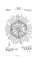
- Fig. 2 is a view in side elevation of the windwheel alone.
- Fig. 3 is a view partly in elevation, and partly in section, showing the construction of the windwheel, and the construction of the gearing for the transversely disposed shaft on which the windwheel is mounted.
- 1 denotes a perpendicular rectangular frame or structure, which may be constructed of vertically arranged beams or uprights suitably braced by angular-1y disposed beams.
- the upper portion of the frame or structure is provided with a platform 2, upon which a cylindrical member 3 is secured, thereby forming a bearing for the revoluble frame 4, which only revolves when the wind currents are changed from one direction to the other.
- This revoluble frame 4. comprises upwardly extending arms 5, in which bearings are formed for the shafts 6 and 7, with which the gears 8 are rotatable. These gears 8 mesh with the pinions 9, which are rotatable with the transversely disposed shaft 10.
- One of the arms 5 has the usual form of vane 11, by which the revoluble frame 4: is rotated, when the Wind currents contact therewith.
- the other arm 5 is formed with an extension 12, to which is pivoted a bell crank lever 13, the purpose of which will hereinafter appear.
- the transversely arranged shaft 10 has mounted thereon the hub of the windwheel 14:.
- This wheel 14 comprises the rock shafts 19 and the hub 15.
- the shafts 19 are braced with regard to the hub, by the tubular members 16.
- the hub 15 is in the form of a casting, which is keyed to rotate with the shaft 10.
- the outer ends of the tubes 16 are provided with collars 17 having bearings 18, for the lurality of rock shafts 19.
- the plurality of rock shafts 19 have secured to them the various windwheel blades 20, the normal positions of which are as shown in Fig. 1.
- These various wind wheel blades may be adjusted at various angles.
- the extreme angle to which the windwheel blades may be adjusted is indicated in Fig. 3. However, the blades may be adjusted at angles intermediate those shown in Fig.
- the rock shafts 19 have projecting laterally therefrom arms 21, between which and a sleeve 22 (which is keyed to rotate with the shaft 10 but slidable thereon), rods 23 .are connected, in order that when the sleeve 22 is shifted upon the shaft 10 toward the revoluble frame 4, the various blades may be thrown in difierent positions or angles.
- the collar 25 limiting thesl-eeve in its movement in the direction of the revoluble frame '4.
- This collar 25 is held adjustable upon the shaft 1 0 by means of the thumb screw 26. Movable upon the sleeve, but
- the lever 32 is fulcrumed, as at 38, to the rack quadrant, and to hold the :dog or rather the nose thereof in engagement with the teeth, a spring 39 is connected *between the dog and the said lever, as at 4'0 and 41.
- a hand grip 42 is pivoted adj acent the handle of the lever 32, as at 43, and between this hand grip and the doga rod 44 is connected, so that as the hand grip is pressed toward the handle of the lever 32, the dog and the nose thereofwil l be drawn from the teeth of the quadrant.
- the windw-heel b'lades may be disposed in various positions, in order to increase or decrease the lifting power of the windmill.
- the windwheel blades When the windwheel blades are arranged in the positions as shown in Fig. '2, thewind currents have a superior-effect upon the blades, thereby increasing the speed of the shaft 10, which, in turn, increases the speed of the vertical up and-down movement of the pump rod 45.
- This pump rod is pivoted, :as at 46, to an arm 47 of the'sleeve 48, which is mounted upon the shaft 49 which 7 integrally connects the gears 8.
- the sleeve 48 is loosely mounted upon the shaft 49, in order to permit the shaft to rdtaite therein, as the gears '8 revolve.
- a bracket 51 to which is fulcrumed, :at52, a swinging fulcrum bar 53.
- a pump handle 54 Pivoted to the fulcrum bar 53 is a pump handle 54, the end of which extends through a slot 56 of the said bracket 51, in order to be pivotally connected, as at 57, to the said pump rod.
- the end 55 of the pump handle, in Fig. l is shown as being disconnected from the pump rod, in order :that the pump rod may be manipulated vertically by the windw heel.
- the connections 33,34, 35, and 36 comprise mainly the sleeve 35 (which is keyed to but slidable upon the lower cylindrical portion of the revoluble member 4) the collar a e (which is movable with the sleeve but slidable around it) and the lever "36.
- the lever 36 is pivoted to a stud of the structure 1, as at 36
- the lever36 is formed with an opening, as will be discerned from. Fig. 1, and in which is arranged the collar 36 and sleeve 35.
- the collar '36 is not only arranged -in the opening but is pivoted ;to the sides of the lever by the studs 36.
- the key 36 which keys the sleeve .35 to the framedis shown in Fig. l as below the said collar.
- Projecting from sleeve 35 is an arm 35*, to which the connection or rod .33 is attached.
- the free end of the lever 36 has connected to its extremity the connection :or rod 34.
- the sleeve 35 As the lever 32 is moved downwardly the sleeve 35 in turn is moved in thesame direction, and by virtue of the connection or rod before stated when the lever 32 is moved downwardly, it may be held in adjusted positions by the nose of the dog 36 engaging the teeth of the rack quadrant, and when so adjusted the lever 36 and the sleeve 35 with its arm 35 are held against the action of the spring 35.
- a revoluble frame and a transversely disposed revoluble driven shaft extending outwardly of the frame, a windwheel movable with the outer end of said shaft and including angularly adjustable blades, a collar rotatable with but slidable on the driven shaft provided with connections for adjusting the blades;
- said revoluble frame having a collar provided with an arm slidably keyed thereon, said collar provided with a swiveled member, a pivoted lever provided with an opening to receive the swiveled member and provided with pivotal connections to the swiveled member, a lever mechanism provided with a rod for moving the pivoted lever upwardly and downwardly, whether the revoluble frame is moving or not, and connections between the arm and the shiftable sleeve of the driven shaft, whereby the blades of the windwheel may be adjusted when the lever mechanism is operated.
Landscapes
- Engineering & Computer Science (AREA)
- Mechanical Engineering (AREA)
- Combustion & Propulsion (AREA)
- Sustainable Development (AREA)
- Sustainable Energy (AREA)
- Chemical & Material Sciences (AREA)
- Life Sciences & Earth Sciences (AREA)
- General Engineering & Computer Science (AREA)
- Power Engineering (AREA)
- Aviation & Aerospace Engineering (AREA)
- Physics & Mathematics (AREA)
- Fluid Mechanics (AREA)
- Wind Motors (AREA)
Description
A. J. SHIRLEY WINDMILL.
uruonrox FILED 0011.1, 1910.
Patented Apr. 11,1911.
3 SHEETS-SHEET 1.
' Swuwwtcw wax/5m IIIIIIIIIIIIIIIIIIIIIIIII 0.
BBBBBBBBBBBBB 2.
ALFRED J'. SHIRLEY, OF ROTHSAY, MINNESOTA.
WINDMILL.
Specification of Letters Patent.
Patented Apr. 11, 1911.
Application filed October 7, 1910. Serial No. 585,792.
To all whom 'it may concern:
Be it known that I, ALFRED J. SHIRLEY, a citizen of the United States, residing at Rothsay, in the county of Wilkin and State of Minnesota, have invented a new and useful Windmill; and I do hereby declare the following to be a full, clear, and exact description of the invention, such as will enable others skilled in the art to which it appertains to make and use the same.
This invention belongs to the art of windmills, and it particularly pertains to a device of this design which may be so operated as to readily and quickly pump or raise water from the well.
The essential object of the invention is the provision of a windwheel, the blades of which may be thrown at various angles to the radial plane thereof, in order to be better contacted with by the wind currents, thereby facilitating the raising or the pumping of the water from the well.
A further object of the invention is to provide means for adjusting and holding when adjusted the said blades. To obtain this result, the windwheel has its hub movable with the transversely arranged shaft (which is suitably geared with the pump rod). The windwheel comprises a plurality of revoluble rods, with which the blades of the windwheel are movable. The revoluble rods are provided with arms which have link connections with a sleeve keyed upon said shaft, but slidable thereon, there being means provided for shifting this sleeve to different locations upon said shaft; said means consist of a collar consisting of two parts, a bell crank lever having connections with said collar, and a lever cooperating with a rack quadrant for shifting the bell crank lever, there being connections between the bell crank lever and the lever cooperating with the quadrant. The lever which cooperates with the quadrant is provided with means for holding the same in various positions.
A further object of the invention is to provide a lever for operating the pump rod manually, in lieu of the aforesaid mechanism. In the drawings, however, there is only disclosed one particular form of the invention, but in practical fields this form may necessitate certain alterations to which the applicant is entitled, provided the alterations are comprehended by the appended Claim.
Further features and combinations of parts will be hereinafter more fully set forth, shown in the drawings and claimed.
In the drawingsz-Figure 1 is a view in side elevation of a windmill embodying the various features of the invention. Fig. 2 is a view in side elevation of the windwheel alone. Fig. 3 is a view partly in elevation, and partly in section, showing the construction of the windwheel, and the construction of the gearing for the transversely disposed shaft on which the windwheel is mounted.
Attention is directed to the accompanying drawings, in which the preferred form of the invention is disclosed; 1 denotes a perpendicular rectangular frame or structure, which may be constructed of vertically arranged beams or uprights suitably braced by angular-1y disposed beams.
The upper portion of the frame or structure is provided with a platform 2, upon which a cylindrical member 3 is secured, thereby forming a bearing for the revoluble frame 4, which only revolves when the wind currents are changed from one direction to the other. This revoluble frame 4. comprises upwardly extending arms 5, in which bearings are formed for the shafts 6 and 7, with which the gears 8 are rotatable. These gears 8 mesh with the pinions 9, which are rotatable with the transversely disposed shaft 10. One of the arms 5 has the usual form of vane 11, by which the revoluble frame 4: is rotated, when the Wind currents contact therewith. The other arm 5 is formed with an extension 12, to which is pivoted a bell crank lever 13, the purpose of which will hereinafter appear.
The transversely arranged shaft 10 has mounted thereon the hub of the windwheel 14:. This wheel 14 comprises the rock shafts 19 and the hub 15. The shafts 19 are braced with regard to the hub, by the tubular members 16. The hub 15 is in the form of a casting, which is keyed to rotate with the shaft 10. The outer ends of the tubes 16 are provided with collars 17 having bearings 18, for the lurality of rock shafts 19. The plurality of rock shafts 19 have secured to them the various windwheel blades 20, the normal positions of which are as shown in Fig. 1. These various wind wheel blades may be adjusted at various angles. The extreme angle to which the windwheel blades may be adjusted is indicated in Fig. 3. However, the blades may be adjusted at angles intermediate those shown in Fig. 3 and the positions of the blades shown in Fig. 1. The rock shafts 19 have projecting laterally therefrom arms 21, between which and a sleeve 22 (which is keyed to rotate with the shaft 10 but slidable thereon), rods 23 .are connected, in order that when the sleeve 22 is shifted upon the shaft 10 toward the revoluble frame 4, the various blades may be thrown in difierent positions or angles. When the sleeve 22 is shifted to the "end of vthe key 24, it will be observed that the windwheel blades are thrown at their extreme angles, the collar 25 limiting thesl-eeve in its movement in the direction of the revoluble frame '4. This collar 25 is held adjustable upon the shaft 1 0 by means of the thumb screw 26. Movable upon the sleeve, but
31 of the bell cranklever When this bell crank lever is manipulated, by means of the lever 32, between which and the bell crank lever, connections 33, 34 and 35 and 36a-re arranged, the sleeve 22 will be shifted in the direction of the collar 25. When the lever 32 is operated to obtain this result, the same is held in its adjusted position, hy means of the dog 36 the nose of which engages any -=one of the 'teeth o-f the rack quadrant 37, which is secured to the frame or structure 1 at the base thereof. The lever 32 is fulcrumed, as at 38, to the rack quadrant, and to hold the :dog or rather the nose thereof in engagement with the teeth, a spring 39 is connected *between the dog and the said lever, as at 4'0 and 41. To withdraw the nose of the dog from engagement with any one of the teeth, a hand grip 42 is pivoted adj acent the handle of the lever 32, as at 43, and between this hand grip and the doga rod 44 is connected, so that as the hand grip is pressed toward the handle of the lever 32, the dog and the nose thereofwil l be drawn from the teeth of the quadrant. By the manipulation of the lever 32, it will be observed that the windw-heel b'lades may be disposed in various positions, in order to increase or decrease the lifting power of the windmill. When the windwheel blades are arranged in the positions as shown in Fig. '2, thewind currents have a superior-effect upon the blades, thereby increasing the speed of the shaft 10, which, in turn, increases the speed of the vertical up and-down movement of the pump rod 45. This pump rod is pivoted, :as at 46, to an arm 47 of the'sleeve 48, which is mounted upon the shaft 49 which 7 integrally connects the gears 8. The sleeve 48 is loosely mounted upon the shaft 49, in order to permit the shaft to rdtaite therein, as the gears '8 revolve.
mg only one shown, as will be seen in Fig. '3. 1
The usual form of pump 50 is disclosed in Fig. 1, and carried at the upper end of the same is a bracket 51, to which is fulcrumed, :at52, a swinging fulcrum bar 53. Pivoted to the fulcrum bar 53 is a pump handle 54, the end of which extends through a slot 56 of the said bracket 51, in order to be pivotally connected, as at 57, to the said pump rod. However, the end 55 of the pump handle, in Fig. l, is shown as being disconnected from the pump rod, in order :that the pump rod may be manipulated vertically by the windw heel. hen the end 55 of the pump handle is disconnected from :the pump rod, the same is prevented from pulling through the slot 56, by virtue of the enlargement 53 at the end of the pump handle 54. This enlargement connects with the pump rod, when it is desired-to mani pulate the same manually. When it is desired to manipulate the pump rod manually, the lower section '59 of the pump rod is disconnected from the upper section 60 thereof, by the removal of the bolt By disconnecting the upper and lower sections 'of the pump rod, the windwheel mechanism,
mounted upon the platform of the frame or structure 1, may be thrown completely out of commission, thus permitting the pump rod to be manually operated.
Upon examining the annexed drawings in connection with the foregoing description, it will be apparent that a novel windmill is devised, and one which may lift a great quantity of water in a very short period of time. Furthermore, it will be apparent that the structure of the apparatus is very simple for a device of this magnitude.
The connections 33,34, 35, and 36 comprise mainly the sleeve 35 (which is keyed to but slidable upon the lower cylindrical portion of the revoluble member 4) the collar a e (which is movable with the sleeve but slidable around it) and the lever "36. The lever 36 is pivoted to a stud of the structure 1, as at 36 The lever36 is formed with an opening, as will be discerned from. Fig. 1, and in which is arranged the collar 36 and sleeve 35. The collar '36 is not only arranged -in the opening but is pivoted ;to the sides of the lever by the studs 36. The key 36 which keys the sleeve .35 to the framedis shown in Fig. l as below the said collar. Projecting from sleeve 35 is an arm 35*, to which the connection or rod .33 is attached. The free end of the lever 36 has connected to its extremity the connection :or rod 34. As the lever 32 is moved downwardly the sleeve 35 in turn is moved in thesame direction, and by virtue of the connection or rod before stated when the lever 32 is moved downwardly, it may be held in adjusted positions by the nose of the dog 36 engaging the teeth of the rack quadrant, and when so adjusted the lever 36 and the sleeve 35 with its arm 35 are held against the action of the spring 35. When the lever 32 is released by withdrawing said nose from the teeth, in order to permit the lever to return to the position shown in Fig. 1, the action of the spring 35 raises the sleeve 35 and the lever 36, thus returning the wind-wheel blades back to the positions shown in Fig. l.
The invention having been set forth, what is claimed as new and useful is The combination of a revoluble frame and a transversely disposed revoluble driven shaft extending outwardly of the frame, a windwheel movable with the outer end of said shaft and including angularly adjustable blades, a collar rotatable with but slidable on the driven shaft provided with connections for adjusting the blades; said revoluble frame having a collar provided with an arm slidably keyed thereon, said collar provided with a swiveled member, a pivoted lever provided with an opening to receive the swiveled member and provided with pivotal connections to the swiveled member, a lever mechanism provided with a rod for moving the pivoted lever upwardly and downwardly, whether the revoluble frame is moving or not, and connections between the arm and the shiftable sleeve of the driven shaft, whereby the blades of the windwheel may be adjusted when the lever mechanism is operated.
In testimony whereof I have signed my name to this specification in the presence of two subscribing witnesses.
ALFRED J. SHIRLEY.
WVitnesses:
I. H. L'UNDER, INGVALD BRIEBY.
Copies of this patent may be obtained for five cents each, by addressing the Commissioner of Patents, Washington, D. G.
Priority Applications (1)
| Application Number | Priority Date | Filing Date | Title |
|---|---|---|---|
| US58579210A US989068A (en) | 1910-10-07 | 1910-10-07 | Windmill. |
Applications Claiming Priority (1)
| Application Number | Priority Date | Filing Date | Title |
|---|---|---|---|
| US58579210A US989068A (en) | 1910-10-07 | 1910-10-07 | Windmill. |
Publications (1)
| Publication Number | Publication Date |
|---|---|
| US989068A true US989068A (en) | 1911-04-11 |
Family
ID=3057406
Family Applications (1)
| Application Number | Title | Priority Date | Filing Date |
|---|---|---|---|
| US58579210A Expired - Lifetime US989068A (en) | 1910-10-07 | 1910-10-07 | Windmill. |
Country Status (1)
| Country | Link |
|---|---|
| US (1) | US989068A (en) |
-
1910
- 1910-10-07 US US58579210A patent/US989068A/en not_active Expired - Lifetime
Similar Documents
| Publication | Publication Date | Title |
|---|---|---|
| US2037528A (en) | Wind motor | |
| US989068A (en) | Windmill. | |
| US1015505A (en) | Windmill. | |
| US1074011A (en) | Windmill. | |
| US215035A (en) | Improvement in wind-wheels | |
| US955305A (en) | Wind-motor. | |
| US279066A (en) | Windmill | |
| US961766A (en) | Wind-motor. | |
| US201286A (en) | Improvement in windmills | |
| US674042A (en) | Windmill. | |
| US1384787A (en) | Windmill | |
| US349197A (en) | Windmill | |
| US619954A (en) | Windmill | |
| US848522A (en) | Wind or water power wheel. | |
| US1197047A (en) | Windmill. | |
| US464680A (en) | Wind-wheel | |
| US1639545A (en) | Automatic control for windmills | |
| US1162912A (en) | Windmill. | |
| US532453A (en) | Wind-wheel | |
| US799598A (en) | Windmill. | |
| US1411137A (en) | Windmill | |
| US321292A (en) | Assigstob of one-foueth | |
| US352108A (en) | Windmill | |
| US679346A (en) | Windmill. | |
| US396084A (en) | Windmill |