US9889999B2 - Sheet supplying device, sheet storing device, sheet using apparatus, and liquid discharging apparatus - Google Patents
Sheet supplying device, sheet storing device, sheet using apparatus, and liquid discharging apparatus Download PDFInfo
- Publication number
- US9889999B2 US9889999B2 US15/296,399 US201615296399A US9889999B2 US 9889999 B2 US9889999 B2 US 9889999B2 US 201615296399 A US201615296399 A US 201615296399A US 9889999 B2 US9889999 B2 US 9889999B2
- Authority
- US
- United States
- Prior art keywords
- separation pressure
- sheet
- spring
- separation
- holder
- Prior art date
- Legal status (The legal status is an assumption and is not a legal conclusion. Google has not performed a legal analysis and makes no representation as to the accuracy of the status listed.)
- Active
Links
Images


Classifications
-
- B—PERFORMING OPERATIONS; TRANSPORTING
- B65—CONVEYING; PACKING; STORING; HANDLING THIN OR FILAMENTARY MATERIAL
- B65H—HANDLING THIN OR FILAMENTARY MATERIAL, e.g. SHEETS, WEBS, CABLES
- B65H3/00—Separating articles from piles
- B65H3/46—Supplementary devices or measures to assist separation or prevent double feed
- B65H3/52—Friction retainers acting on under or rear side of article being separated
- B65H3/5207—Non-driven retainers, e.g. movable retainers being moved by the motion of the article
- B65H3/5215—Non-driven retainers, e.g. movable retainers being moved by the motion of the article the retainers positioned under articles separated from the top of the pile
- B65H3/5223—Retainers of the pad-type, e.g. friction pads
-
- B—PERFORMING OPERATIONS; TRANSPORTING
- B65—CONVEYING; PACKING; STORING; HANDLING THIN OR FILAMENTARY MATERIAL
- B65H—HANDLING THIN OR FILAMENTARY MATERIAL, e.g. SHEETS, WEBS, CABLES
- B65H3/00—Separating articles from piles
- B65H3/02—Separating articles from piles using friction forces between articles and separator
-
- B—PERFORMING OPERATIONS; TRANSPORTING
- B41—PRINTING; LINING MACHINES; TYPEWRITERS; STAMPS
- B41J—TYPEWRITERS; SELECTIVE PRINTING MECHANISMS, i.e. MECHANISMS PRINTING OTHERWISE THAN FROM A FORME; CORRECTION OF TYPOGRAPHICAL ERRORS
- B41J11/00—Devices or arrangements of selective printing mechanisms, e.g. ink-jet printers or thermal printers, for supporting or handling copy material in sheet or web form
- B41J11/007—Conveyor belts or like feeding devices
-
- B—PERFORMING OPERATIONS; TRANSPORTING
- B65—CONVEYING; PACKING; STORING; HANDLING THIN OR FILAMENTARY MATERIAL
- B65H—HANDLING THIN OR FILAMENTARY MATERIAL, e.g. SHEETS, WEBS, CABLES
- B65H7/00—Controlling article feeding, separating, pile-advancing, or associated apparatus, to take account of incorrect feeding, absence of articles, or presence of faulty articles
-
- B—PERFORMING OPERATIONS; TRANSPORTING
- B65—CONVEYING; PACKING; STORING; HANDLING THIN OR FILAMENTARY MATERIAL
- B65H—HANDLING THIN OR FILAMENTARY MATERIAL, e.g. SHEETS, WEBS, CABLES
- B65H2511/00—Dimensions; Position; Numbers; Identification; Occurrences
- B65H2511/20—Location in space
-
- B—PERFORMING OPERATIONS; TRANSPORTING
- B65—CONVEYING; PACKING; STORING; HANDLING THIN OR FILAMENTARY MATERIAL
- B65H—HANDLING THIN OR FILAMENTARY MATERIAL, e.g. SHEETS, WEBS, CABLES
- B65H2515/00—Physical entities not provided for in groups B65H2511/00 or B65H2513/00
- B65H2515/30—Forces; Stresses
- B65H2515/34—Pressure, e.g. fluid pressure
Definitions
- the present disclosure relates to a sheet supplying device, a sheet storing device, a sheet using apparatus, and a liquid discharging apparatus.
- a sheet supplying device which separates and supplies stacked sheets one by one.
- a friction-type sheet supplying device which uses a separation pad (friction pad) for separating sheets.
- this type of sheet supplying device has low robustness with respect to variation in sheet thickness and is likely to cause multiple feeding or non-feeding.
- a sheet supplying device includes a separator to separate sheets one by one.
- the separator includes a separation pad, a spring, and a separation pressure adjuster.
- the separation pad contacts each of the sheets.
- the spring applies a separation pressure to the separation pad.
- the separation pressure adjuster adjusts the separation pressure to one of separation pressure values variable in multiple steps.
- a sheet storing device includes a container to contain sheets and a separator to separate the sheets contained in the container one by one.
- the separator includes a separation pad, a spring, and a separation pressure adjuster.
- the separation pad contacts each of the sheets.
- the spring applies a separation pressure to the separation pad.
- the separation pressure adjuster adjusts the separation pressure to one of separation pressure values variable in multiple steps.
- a sheet using apparatus includes the above sheet storing device and a liquid discharger to discharge a liquid on the sheet to form an image.
- a liquid discharging apparatus includes the above sheet storing device and a liquid discharger to discharge a liquid on the sheet to form an image.
- FIG. 1 is a perspective outline view of a sheet using apparatus according to an embodiment of the present invention
- FIG. 2 is a perspective view of a mechanical section of the sheet using apparatus illustrated in FIG. 1 ;
- FIG. 3 is a plan view of a major part of the mechanical section illustrated in FIG. 2 ;
- FIG. 4 is a side view of a carriage included in the sheet using apparatus illustrated in FIG. 1 ;
- FIGS. 5 and 6 are cross-sectional and perspective views, respectively, of a sheet supplying device according a first embodiment of the present invention, attached to a supply cassette;
- FIGS. 7 and 8 are perspective and elevation views of a spring holder included in the sheet supplying device illustrated in FIGS. 5 and 6 ;
- FIG. 9 is a perspective view of a major part of a sheet supplying device according to a second embodiment of the present invention.
- FIG. 10 is a perspective view of a spring holder included in a sheet supplying apparatus according to a third embodiment of the present invention.
- FIG. 11 is a plan view of the spring holder illustrated in FIG. 10 mounted on a holder receiver;
- FIGS. 12A and 12B are side views of a major part of a sheet supplying device according to a fourth embodiment of the present invention.
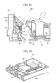
- FIGS. 13 and 14 are side and elevation views, respectively, of a major part of a sheet supplying device according to a fifth embodiment of the present invention.
- FIGS. 15 and 16 are side and elevation views, respectively, of a major part of a sheet supplying device according to a sixth embodiment of the present invention.
- FIG. 17 is a side view of a major part of a sheet storing device according to a seventh embodiment of the present invention.
- FIG. 18 is a side view of a major part of a sheet storing device according to an eighth embodiment of the present invention.
- FIG. 19 is a perspective view of a container included in the sheet storing device illustrated in FIG. 18 ;
- FIG. 20 is a magnified perspective view of a major part of the container illustrated in FIG. 19 .
- a sheet supplying device which easily properly adjusts the separation pressure.
- FIG. 1 is a perspective outline view of a sheet using apparatus according to an embodiment of the present invention.
- FIG. 2 is a perspective view of a mechanical section of the sheet using apparatus illustrated in FIG. 1 .
- FIG. 3 is a plan view of a major part of the mechanical section illustrated in FIG. 2 .
- FIG. 4 is a side view of a carriage included in the sheet using apparatus illustrated in FIG. 1 .
- the sheet using apparatus illustrated in FIG. 1 is configured to discharge a liquid onto a sheet to form an image thereon.
- the sheet using apparatus includes an apparatus body 101 , a supply cassette 102 serving as a sheet storing device, and an ejection tray 103 for stacking ejected sheets thereon.
- the supply cassette 102 is detachably attached to a front surface side of the apparatus body 101 .
- the ejection tray 103 is disposed above the supply cassette 102 .
- a cover 104 is disposed on a right side of the front surface of the apparatus body 101 .
- the cover 104 is openable and closable. When the cover 104 is opened, a liquid cartridge 62 can be attached to or detached from a cartridge holder 61 disposed in the apparatus body 101 .
- a guide member 3 formed of a platy member, is stretched between a pair of side plates 1 A and 1 B, and a carriage 4 is supported by the guide member 3 so as to be movable in the main scanning direction.
- a main scanning motor 5 moves the carriage 4 in the main scanning direction via a timing belt 8 that is wound around a driving pulley 6 and a driven pulley 7 .
- the guide member 3 is a platy member that guides movement of the carriage 4 .
- the guide member 3 has a guide surface 3 a serving as a support surface for guiding the carriage 4 , and other guide surfaces 3 b and 3 c.
- the carriage 4 has a rodless guide mechanism including a height adjuster 4 a , a contact part 4 b , and another contact part 4 c .
- the height adjuster 4 a is movably supported by the guide surface 3 a of the guide member 3 .
- the contact part 4 b movably contacts the guide surface 3 b of the guide member 3 .
- the contact part 4 c movably contacts the guide surface 3 c of the guide member 3 .
- the carriage 4 includes heads 11 a and 11 b (hereinafter may be collectively “heads 11 ”) for discharging liquids.
- heads 11 Each of the heads 11 a and 11 b has two nozzle arrays.
- the four nozzle arrays, in total, are assigned to discharge liquids of yellow, cyan, magenta, and black, respectively.
- the heads 11 a and 11 b integrally support respective head tanks 12 a and 12 b (hereinafter may be collectively “head tanks 12 ”) for supplying liquids.
- the liquid cartridge 62 is detachably mountable on the cartridge holder 61 .
- a pump unit 63 supplies a liquid contained in the liquid cartridge 62 to the head tanks 12 via a supply tube 64 (illustrated in FIG. 2 ).
- An encoder scale 15 is disposed along the main scanning direction of the carriage 4 .
- An encoder sensor 16 for reading the scale of the encoder scale 15 is mounted on the carriage 4 .
- the encoder sensor 16 is formed of a transmission photosensor.
- the encoder scale 15 and the encoder sensor 16 form a linear encoder serving as a position detector.
- a conveyance belt 21 for conveying a sheet 10 in the sub-scanning direction is disposed below the carriage 4 .
- the conveyance belt 21 is an endless belt stretched between a conveyance roller 22 and a tension roller 23 .
- a sub-scanning motor 31 rotary-drives the conveyance roller 22 via a timing belt 32 and a timing pulley 33 , to cause the conveyance belt 21 to circumferentially move in the sub-scanning direction.
- sheet guide members 51 and 52 are disposed in the vicinity of entrance and exit parts, respectively, of the conveyance belt 21 .
- a maintenance unit 41 for maintaining the heads 11 is disposed on one lateral side of the conveyance belt 21 in the main scanning direction of the carriage 4 .
- the maintenance unit 41 includes a suction cap 42 a and a moisture-retention cap 42 b for capping the nozzle surfaces of the heads 11 , a wiper 43 for wiping the nozzle surfaces, and a dummy discharge receptacle 44 for receiving dummy discharge liquid during maintenance.
- the suction cap 42 a is connected to a suction pump serving as a suction device.
- the sheet 10 fed from the supply cassette 102 is intermittently conveyed by the conveyance belt 21 , while the carriage 4 is moved in the main scanning direction and the heads 11 are driven according to an image signal.
- This operation records one line of an image on the sheet 10 with the liquid discharged from the heads 11 .
- this operation is repeated to record next line of the image on the sheet 10 .
- Such a sheet-conveying and image-recording operation is repeated until formation of the image is completed.
- the sheet 10 having the image thereon is ejected from the apparatus body 100 .
- FIGS. 5 and 6 are cross-sectional and perspective views, respectively, of a sheet supplying device 301 attached to the supply cassette 102 .
- FIGS. 7 and 8 are perspective and elevation views of a spring holder 318 included in the sheet supplying device 300 .
- the supply cassette 102 includes a cassette body 201 for storing multiple sheets 10 and a bottom plate 202 for stacking the sheets 10 thereon.
- the sheet supplying device 301 includes a supply roller 312 mounted on a shaft 311 . On both axial ends of the supply roller 312 , supply roller collars 313 are respectively disposed.
- a separator 303 is disposed facing the supply roller 312 .
- the separator 303 includes a friction pad 314 serving as a separation pad, and a friction pad holder 315 for holding the friction pad 314 .
- the friction pad holder 315 has a shaft part 315 a on a downstream side relative to the sheet supplying direction.
- the shaft part 315 a is supported by a supply guide member 310 to make the friction pad holder 315 swingable.
- a spring 317 is disposed on the opposite side of the friction pad 314 relative to the friction pad holder 315 .
- the spring 317 applies a separation pressure to the friction pad 314 .
- the spring 317 is held by a spring holder 318 .
- the spring holder 318 combines the function of adjusting the separation pressure, to be applied to the friction pad 314 , to separation pressure values preset in multiple steps.
- the spring holder 318 is movably held by a holder receiver 304 .
- the spring holder 318 is in contact with one end part a friction pad pressing lever 319 .
- the friction pad pressing lever 319 has a shaft part 319 a .
- the shaft part 319 a is supported by a support 305 (illustrated in FIG. 6 ) to make the friction pad pressing lever 319 swingable.
- a front plate 204 disposed on a front side of the cassette body 201 in the mounting direction, presses the friction pad pressing lever 319 .
- the friction pad pressing lever 319 thereby rotates in a direction indicated by arrow in FIG. 5 to push up the spring holder 318 .
- the friction pad pressing lever 319 is configured to release the separation pressure.
- the one end of the friction pad pressing lever 319 in contact with the spring holder 318 is separated therefrom and the spring 317 restores to its original state.
- the separation pressure is released.
- the spring holder 318 has spring receiving parts 318 a 1 and 318 a 2 and a mounting part 318 b to be movably fitted into the holder receiver 304 .
- the spring holder 318 When mounted on the holder receiver 304 , the spring holder 318 may be in either a regular posture as illustrated in FIGS. 7 and 8 or an upside-down posture.
- the distance between the friction pad pressing lever 319 and the seat of the spring 317 i.e., the bottom surface of the spring receiving part 318 a 1
- the distance between the friction pad pressing lever 319 and the seat of the spring 317 i.e., the bottom surface of the spring receiving part 318 a 2
- B the distance between the friction pad pressing lever 319 and the seat of the spring 317
- the cassette body 201 of the supply cassette 102 presses the friction pad pressing lever 319 .
- the friction pad pressing lever 319 thereby rotates about the shaft part 319 a in a direction indicated by arrow in FIG. 5 , thus becoming a state illustrated in FIG. 5 .
- the separation pressure from the friction pad 314 is determined depending on the working length (i.e., compression amount) of the spring 317 .
- the spring holder 318 in the regular posture is mounted on the holder receiver 304 .
- the distance between the friction pad pressing lever 319 and the seat of the spring 317 becomes A.
- the separation pressure from the friction pad is adjustable to separation pressure values preset in multiple steps. This configuration achieves much easier and more appropriate adjustment of the separation pressure compared to a case in which the separation pressure is adjustable continuously.
- the method of changing the mounting posture of the spring holder is not limited to turning the spring holder upside down in the vertical direction.
- the mounting posture can be varied by rotating the spring holder by 90 degrees.
- FIG. 9 is a perspective view of a major part of the sheet supplying device according to the second embodiment of the present invention.
- the friction pad pressing lever 319 used in the first embodiment is omitted.
- the working length (i.e., compression amount) of the spring 317 is changed.
- the separation pressure is adjustable in multiple steps.
- the spring holder 318 needs not to be movable so long as the working length (i.e., compression amount) of the spring 317 is variable in accordance with a change in mounting posture on the holder receiver 304 . Therefore, the spring holder 318 in the second embodiment, illustrated in FIG. 9 , has a different shape from that in the first embodiment. Of course, the spring holder 318 in the second embodiment may have the same shape as that in the first embodiment.
- FIG. 10 is a perspective view of the spring holder 318 included in the sheet supplying device according to the third embodiment.
- FIG. 11 is a plan view of the spring holder 318 illustrated in FIG. 10 mounted on the holder receiver 304 .
- the spring holder 318 has an improper assembly preventing part 318 c serving as a posture regulator.
- a gap G is formed between the improper assembly preventing part 318 c and the mounting part 318 b . More specifically, the gap G is formed between an outer peripheral wall surface of the mounting part 318 b and an inner wall surface (i.e., the surface facing the mounting part 318 b ) of the improper assembly preventing part 318 c .
- the improper assembly preventing part 318 c has a cutout 318 d .
- the improper assembly preventing part 318 c is easily removable by being broken.
- the holder receiver 304 has guide parts 304 a and 304 b for guiding the mounting part 318 b of the spring holder 318 .
- the guide part 304 a has a thickness t 1 less then than the gap G formed by the improper assembly preventing part 318 c .
- the guide part 304 b has a thickness t 2 greater than the gap G formed by the improper assembly preventing part 318 c.
- the mounting part 318 b of the spring holder 318 cannot be mounted on the holder receiver 304 unless the guide part 304 a of the holder receiver 304 can be fitted into the gap G formed by the improper assembly preventing part 318 c.
- the initial mounting posture of the spring holder 318 is thus automatically determined and prevented from being mounted on the holder receiver 304 in the upside-down posture.
- the spring holder 318 in the upside-down posture can be mounted on the holder receiver 304 .
- FIGS. 12A and 12B are side views of a major part of the sheet supplying device according to the fourth embodiment of the present invention.
- a spring holder 328 includes a spring receiving part 328 a , a shaft part 328 b , and a lever part 328 c .
- the shaft part 328 b is rotatably held by a holder receiver 329 .
- the lever part 328 c is to be pressed by the cassette body 201 of the supply cassette 102 .
- the holder receiver 329 has holding parts 329 a and 329 b each disposed at different heights, for holding the shaft part 328 b of the spring holder 328 .
- the holder receiver 329 serves as a separation pressure adjuster.
- the height of the spring holder 328 is varied depending on which one of the holding parts 329 a and 329 b is holding the shaft part 328 b of the spring holder 328 .
- the working length (i.e., compression amount) of the spring 317 is varied to vary (adjust) the separation pressure in multiple steps.
- FIGS. 13 and 14 are side and elevation views, respectively, of a major part of the sheet supplying device according to the fifth embodiment of the present invention.
- a spring holder 328 includes a spring receiving part 328 a , a shaft part 328 b , and a lever part 328 c .
- the shaft part 328 b is rotatably held by a holder receiver.
- the lever part 328 c is to be pressed by the cassette body 201 of the supply cassette 102 .
- the lever part 328 c of the spring holder 328 is equipped with an adjuster 340 .
- the adjuster 340 varies the contact distance between the lever part 328 c and the supply cassette 102 to adjust the separation pressure.
- the adjuster 340 has a circular disc shape.
- the adjuster 340 has multiple projections 340 a , 340 b , and 340 c each different in height, to be brought into contact with the supply cassette 102 .
- a rotary knob 341 is attached to the adjuster 340 with a plate spring 342 .
- the adjuster 340 rotates, the contact distance between the lever part 328 c and the supply cassette 102 is varied, the amount of tilt of the spring holder 328 is thereby varied, and the working length (i.e., compression amount) of the spring 317 is thereby varied to vary (adjust) the separation pressure in multiple steps.
- FIGS. 15 and 16 are side and elevation views, respectively, of a major part of the sheet supplying device according to the sixth embodiment of the present invention.
- a spring holder 358 includes a spring receiving part 358 a , a shaft part 358 b , and a work knob 358 c .
- the shaft part 358 b is rotatably held by a holder receiver 359 .
- the holder receiver 359 has holding parts 359 a and 359 b each disposed at different heights, for holding the shaft part 358 b of the spring holder 358 .
- the holder receiver 359 has a fall preventing part 359 c having elasticity, for preventing the shaft part 358 b from falling off when held by the holding part 359 a or 359 b.
- the height of the spring holder 358 is varied depending on which one of the holding parts 359 a and 359 b is holding the shaft part 358 b of the spring holder 358 .
- the working length (i.e., compression amount) of the spring 317 is varied to vary (adjust) the separation pressure in multiple steps.
- FIG. 17 is a side view of a major part of the sheet storing device according to the seventh embodiment of the present invention.
- a sheet storing device 500 includes a container 501 for containing sheets 10 and a separator 503 for separating and supplying the sheets 10 contained in the container 501 one by one.
- the container 501 includes a container body 601 for storing multiple sheets 10 , a bottom plate 602 for stacking the sheets 10 thereon, and a guide member 610 for guiding the sheets 10 to be fed.
- the separator 503 includes a friction pad 614 serving as a separation pad, and a friction pad holder 615 for holding the friction pad 614 .
- the friction pad 614 faces the supply roller 312 when the sheet storing device 500 is mounted on the above-described sheet using device.
- the friction pad holder 615 has a shaft part 615 a on a downstream side relative to the sheet supplying direction.
- the shaft part 615 a is supported by the guide member 610 of the container body 601 to make the friction pad holder 615 swingable.
- a spring 617 is disposed on the opposite side of the friction pad 614 relative to the friction pad holder 615 .
- the spring 617 applies a separation pressure to the friction pad 614 .
- the spring 617 is held by a spring holder 618 .
- the spring holder 618 combines the function of adjusting the separation pressure, to be applied to the friction pad 614 , to separation pressure values present in multiple steps.
- the spring holder 618 is held by a holder receiving part 604 of the guide member 610 .
- the spring holder 618 may be in either a regular posture or an upside-down posture, similar to the first and third embodiments.
- the separation pressure is adjustable in multiple steps.
- the spring holder 618 and the holder receiving part 604 may include a posture regulator.
- FIG. 18 is a side view of a major part of the sheet storing device according to the eighth embodiment.
- FIG. 19 is a perspective view of a container included in the sheet storing device illustrated in FIG. 18 .
- FIG. 20 is a magnified perspective view of a major part of the container illustrated in FIG. 19 .
- a sheet storing device 800 includes a container 801 for containing sheets 10 and a separator 803 for separating and supplying the sheets 10 contained in the container 801 one by one.
- the container 801 includes a cassette body 901 for storing multiple sheets 10 and a bottom plate 902 for stacking the sheets 10 thereon.
- the separator 803 includes a friction pad 914 serving as a separation pad, and a friction pad holder 915 for holding the friction pad 914 .
- the friction pad 914 faces the supply roller 312 when the sheet storing device 800 is mounted on the above-described sheet using device.
- the friction pad holder 915 has a shaft part 915 a on a downstream side relative to the sheet supplying direction.
- the shaft part 915 a is supported by a guide member 910 to make the friction pad holder 915 swingable.
- a spring 917 is disposed on the opposite side of the friction pad 914 relative to the friction pad holder 915 .
- the spring 917 applies a separation pressure to the friction pad 914 .
- the spring 917 is held by a spring holder 918 .
- the spring holder 918 is movably held by a holder receiver 904 .
- the spring holder 918 is in contact with one end part a friction pad pressing lever 919 .
- the friction pad pressing lever 919 has a shaft part 919 a .
- the shaft part 919 a is supported by a support 905 to make the friction pad pressing lever 919 swingable.
- the cassette body 901 of the container 801 is equipped with an adjuster 940 , similar to the adjuster 340 of the fifth embodiment, disposed on a front side of the cassette body 901 relative to the mounting direction thereof.
- the adjuster 940 varies the amount of rotation of the friction pad pressing lever 919 .
- the adjuster 940 has a circular disc shape.
- the adjuster 940 has multiple projections 940 a , 940 b , and 940 c each different in height, to be brought into contact with the friction pad pressing lever 919 .
- the amount of rotation of the friction pad pressing lever 919 is varied, the amount of movement of the spring holder 918 is varied, and the working length (i.e., compression amount) of the spring 917 is thereby varied to vary (adjust) the separation pressure in multiple steps.
- the sheet using apparatus serves as a liquid discharging apparatus
- the sheet supplying device supplies sheets to the liquid discharging apparatus
- the sheet storing device stores sheets to be supplied to the liquid discharging apparatus.
- the sheet using apparatus may be configured to form (record, print) not only an image (including tests and graphics) but also a circuit pattern on a sheet material.
Landscapes
- Engineering & Computer Science (AREA)
- Mechanical Engineering (AREA)
- Sheets, Magazines, And Separation Thereof (AREA)
Abstract
Description
Claims (11)
Applications Claiming Priority (2)
| Application Number | Priority Date | Filing Date | Title |
|---|---|---|---|
| JP2015-224202 | 2015-11-16 | ||
| JP2015224202A JP6606990B2 (en) | 2015-11-16 | 2015-11-16 | Equipment that uses sheet material, equipment that supplies sheet material |
Publications (2)
| Publication Number | Publication Date |
|---|---|
| US20170136784A1 US20170136784A1 (en) | 2017-05-18 |
| US9889999B2 true US9889999B2 (en) | 2018-02-13 |
Family
ID=58690512
Family Applications (1)
| Application Number | Title | Priority Date | Filing Date |
|---|---|---|---|
| US15/296,399 Active US9889999B2 (en) | 2015-11-16 | 2016-10-18 | Sheet supplying device, sheet storing device, sheet using apparatus, and liquid discharging apparatus |
Country Status (2)
| Country | Link |
|---|---|
| US (1) | US9889999B2 (en) |
| JP (1) | JP6606990B2 (en) |
Families Citing this family (3)
| Publication number | Priority date | Publication date | Assignee | Title |
|---|---|---|---|---|
| US10532591B2 (en) | 2016-12-06 | 2020-01-14 | Ricoh Company, Ltd. | Cloth holder stacker, fabric printing apparatus, and heating device |
| JP6930281B2 (en) * | 2017-08-10 | 2021-09-01 | 株式会社リコー | Sheet transfer device, image reading device and image forming device |
| EP4349605A3 (en) | 2022-09-15 | 2024-06-05 | Ricoh Company, Ltd. | Liquid discharge apparatus |
Citations (2)
| Publication number | Priority date | Publication date | Assignee | Title |
|---|---|---|---|---|
| JPH05238575A (en) | 1992-02-25 | 1993-09-17 | Ricoh Co Ltd | Paper feeder |
| JP2011178514A (en) * | 2010-03-01 | 2011-09-15 | Ricoh Co Ltd | Separating and feeding device and image forming device |
-
2015
- 2015-11-16 JP JP2015224202A patent/JP6606990B2/en active Active
-
2016
- 2016-10-18 US US15/296,399 patent/US9889999B2/en active Active
Patent Citations (2)
| Publication number | Priority date | Publication date | Assignee | Title |
|---|---|---|---|---|
| JPH05238575A (en) | 1992-02-25 | 1993-09-17 | Ricoh Co Ltd | Paper feeder |
| JP2011178514A (en) * | 2010-03-01 | 2011-09-15 | Ricoh Co Ltd | Separating and feeding device and image forming device |
Also Published As
| Publication number | Publication date |
|---|---|
| US20170136784A1 (en) | 2017-05-18 |
| JP2017088384A (en) | 2017-05-25 |
| JP6606990B2 (en) | 2019-11-20 |
Similar Documents
| Publication | Publication Date | Title |
|---|---|---|
| US8070150B2 (en) | Sheet ejection device, image forming apparatus and sheet finisher provided therewith | |
| US8925436B2 (en) | Sheet cutting device and image forming apparatus including the sheet cutting device | |
| US8727468B2 (en) | Recording apparatus | |
| US20050128276A1 (en) | Image forming apparatus | |
| US8801159B2 (en) | Ink-jet recording apparatus | |
| US8469352B2 (en) | Image forming apparatus with rotatable sheet feed unit | |
| US9889999B2 (en) | Sheet supplying device, sheet storing device, sheet using apparatus, and liquid discharging apparatus | |
| US8573723B2 (en) | Image forming apparatus including recording head for ejecting liquid droplets | |
| JP2007091445A (en) | Paper feeding device and image recording apparatus having the same | |
| US8967028B2 (en) | Sheet cutting device and image forming apparatus including the sheet cutting device | |
| JP5327449B2 (en) | Image forming apparatus | |
| EP3345849B1 (en) | Automatic roller clamp | |
| US8491090B2 (en) | Image forming apparatus | |
| US9457596B2 (en) | Sheet feeder and image forming apparatus including same | |
| KR100251120B1 (en) | Auto sheet feed device of office automation system | |
| EP2845742A1 (en) | Image forming apparatus | |
| JP7215208B2 (en) | Liquid ejection unit and liquid ejection device | |
| US7909455B2 (en) | Method and apparatus for forming image | |
| US7488055B2 (en) | Method and apparatus for image forming using an ink-jet printing system | |
| US7543810B2 (en) | Feeder for objects to be conveyed, and image recording device having same | |
| US11376853B2 (en) | Waste liquid recovery apparatus and inkjet recording apparatus | |
| US8905513B2 (en) | Image forming apparatus | |
| US20250296365A1 (en) | Image forming apparatus | |
| US20070115319A1 (en) | Image forming apparatus, maintenance-recovery mechanism, and suction pump | |
| JP3997426B2 (en) | Recording device |
Legal Events
| Date | Code | Title | Description |
|---|---|---|---|
| AS | Assignment |
Owner name: RICOH COMPANY, LTD., JAPAN Free format text: ASSIGNMENT OF ASSIGNORS INTEREST;ASSIGNOR:UENO, SATOSHI;REEL/FRAME:040415/0376 Effective date: 20160912 Owner name: RICOH COMPANY, LTD., JAPAN Free format text: ASSIGNMENT OF ASSIGNORS INTEREST;ASSIGNOR:UENO, SATOSHI;REEL/FRAME:040414/0889 Effective date: 20160912 |
|
| STCF | Information on status: patent grant |
Free format text: PATENTED CASE |
|
| MAFP | Maintenance fee payment |
Free format text: PAYMENT OF MAINTENANCE FEE, 4TH YEAR, LARGE ENTITY (ORIGINAL EVENT CODE: M1551); ENTITY STATUS OF PATENT OWNER: LARGE ENTITY Year of fee payment: 4 |
|
| MAFP | Maintenance fee payment |
Free format text: PAYMENT OF MAINTENANCE FEE, 8TH YEAR, LARGE ENTITY (ORIGINAL EVENT CODE: M1552); ENTITY STATUS OF PATENT OWNER: LARGE ENTITY Year of fee payment: 8 |