US9886775B2 - Method for detecting horizontal and gravity directions of an image - Google Patents
Method for detecting horizontal and gravity directions of an image Download PDFInfo
- Publication number
- US9886775B2 US9886775B2 US15/306,980 US201415306980A US9886775B2 US 9886775 B2 US9886775 B2 US 9886775B2 US 201415306980 A US201415306980 A US 201415306980A US 9886775 B2 US9886775 B2 US 9886775B2
- Authority
- US
- United States
- Prior art keywords
- gray
- attention focus
- image
- function
- orientation
- Prior art date
- Legal status (The legal status is an assumption and is not a legal conclusion. Google has not performed a legal analysis and makes no representation as to the accuracy of the status listed.)
- Active
Links
Images


Classifications
-
- G—PHYSICS
- G06—COMPUTING OR CALCULATING; COUNTING
- G06T—IMAGE DATA PROCESSING OR GENERATION, IN GENERAL
- G06T7/00—Image analysis
- G06T7/70—Determining position or orientation of objects or cameras
-
- G—PHYSICS
- G06—COMPUTING OR CALCULATING; COUNTING
- G06T—IMAGE DATA PROCESSING OR GENERATION, IN GENERAL
- G06T7/00—Image analysis
- G06T7/60—Analysis of geometric attributes
-
- G—PHYSICS
- G06—COMPUTING OR CALCULATING; COUNTING
- G06T—IMAGE DATA PROCESSING OR GENERATION, IN GENERAL
- G06T2207/00—Indexing scheme for image analysis or image enhancement
- G06T2207/10—Image acquisition modality
- G06T2207/10004—Still image; Photographic image
-
- G—PHYSICS
- G06—COMPUTING OR CALCULATING; COUNTING
- G06T—IMAGE DATA PROCESSING OR GENERATION, IN GENERAL
- G06T2207/00—Indexing scheme for image analysis or image enhancement
- G06T2207/20—Special algorithmic details
- G06T2207/20021—Dividing image into blocks, subimages or windows
-
- G—PHYSICS
- G06—COMPUTING OR CALCULATING; COUNTING
- G06T—IMAGE DATA PROCESSING OR GENERATION, IN GENERAL
- G06T2207/00—Indexing scheme for image analysis or image enhancement
- G06T2207/20—Special algorithmic details
- G06T2207/20084—Artificial neural networks [ANN]
-
- G—PHYSICS
- G06—COMPUTING OR CALCULATING; COUNTING
- G06T—IMAGE DATA PROCESSING OR GENERATION, IN GENERAL
- G06T2207/00—Indexing scheme for image analysis or image enhancement
- G06T2207/30—Subject of image; Context of image processing
- G06T2207/30244—Camera pose
-
- G—PHYSICS
- G06—COMPUTING OR CALCULATING; COUNTING
- G06T—IMAGE DATA PROCESSING OR GENERATION, IN GENERAL
- G06T2207/00—Indexing scheme for image analysis or image enhancement
- G06T2207/30—Subject of image; Context of image processing
- G06T2207/30248—Vehicle exterior or interior
- G06T2207/30252—Vehicle exterior; Vicinity of vehicle
Definitions
- the present invention relates to the field of image processing, in particular to a method for detecting the horizontal and gravity directions of an image.
- Detection of the horizontal and gravity directions of an image can be used in vehicle rollover warning, image tilt detection and so on, wherein the image tilt detection can be used in such applications as automatic scanning of images and image correction.
- the purpose of the present invention is to provide a method for detecting the horizontal and gravity directions of an image to realize effective and accurate detection.
- the present invention provides a method for detecting the horizontal and gravity directions of an image, which is used for gray images and comprises:
- M CGCS ⁇ ( ⁇ ) ⁇ - ⁇ + ⁇ ⁇ k e ⁇ ( ⁇ - ⁇ ) ⁇ O I ⁇ ( ⁇ ) ⁇ d ⁇ ⁇ ⁇ , wherein ⁇ is a given constant and ⁇ [0, ⁇ /2), and then obtaining the horizontal and gravity identification angles ⁇ argmaxM CGCS ( ⁇ ), argmaxM CGCS ( ⁇ )+ ⁇ /2 ⁇ .
- the diameter of the sampling circle of the attention focus detector is 0.06 times of the short side length of the image.
- step S 2 specifically includes:
- step S 3 specifically includes:
- s max 255 ⁇ ⁇ ⁇ ⁇ V ⁇ ( VL ⁇ ( x , y ) ) ⁇ dxdy
- ⁇ s min - 255 ⁇ ⁇ ⁇ ⁇ V ⁇ ( - VL ⁇ ( x , y ) ) ⁇ dxdy
- V ⁇ ( k ) ⁇ k , k > 0 0 , k ⁇ 0 ;
- the method for detecting the horizontal and gravity directions of an image according to the present invention has a fast processing speed and good effect, and it is suitable for direction detection for images with the presence of actual gravity or sensory gravity, such as paintings, natural images, texts and so on.
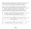
- FIG. 1 is a flow chart of the method for detecting the horizontal and gravity directions of an image according to the present invention
- FIG. 2 is a schematic drawing of the distribution of attention focus detectors for the method for detecting the horizontal and gravity directions of an image according to the present invention.
- the present invention uses an attention focus detector to acquire all attention focus coordinates and the corresponding significant orientation angles in the image coordinate system to constitute a set ⁇ p , and for each element in ⁇ p , an orientation perceptron is used to construct a corresponding local orientation function Dir i ( ⁇ ) according to gray image information, and then an image direction function P I ( ⁇ ) is obtained by summing. On this basis, a horizontal and gravity identification is performed to obtain the horizontal and gravity identification angles, thereby completing detection of the horizontal and gravity directions of the image.
- FIG. 1 is a flow chart of a method for detecting the horizontal and gravity directions of an image according to the present invention. As shown in FIG. 1 , the present invention specifically comprises the following steps:
- FIG. 2 is a schematic drawing of the distribution of attention focus detectors for the method for detecting the horizontal and gravity directions of an image according to the present invention, wherein the diameter of the sampling circle of the attention focus detector is 0.06 times of the short side length of the image.
- the points in FIG. 2 are sampling points, and the circles are the sampling circles of the attention focus detectors.
- Step 102 placing the center of the sampling circle of the attention focus detector on each of the sampling points respectively, and using the attention focus detector to acquire attention focus coordinates (x i , y i ) and the corresponding significant orientation angle ⁇ i ( ⁇ i ⁇ [0, ⁇ ), wherein the subscript i is corresponding to the ith attention focus and i is a natural number, and all attention focus coordinates and the corresponding significant orientation angles constitute a set ⁇ p .
- step 102 includes following steps:
- the attention focus detector stops detecting, otherwise, the central point of the short arc formed between the two pixel points corresponding to the maximum one of the absolute values of the differences is used as the first gray sudden change point p m .
- Step 1022 calculating gray means G up , G down , G left and G right for four square areas, which are above, below, to the left and to the right of the first gray sudden change point p m and whose side lengths are 1/10 of the diameter, and calculating an angle C pm according to the following formula:
- Step 1023 constructing a chord from the first gray sudden change point p m along a direction perpendicular to C pm , said chord intersecting with the sampling circle at another intersection point p o , and searching for a second gray sudden change point near the intersection point p o along the sampling circle, if the second gray sudden change point does not exist, said attention focus detector stops detecting; if the second gray sudden change point exists, it is marked as p m ′, and the central point of the line p m p m ′ between the first gray sudden change point and the second gray sudden change point is used as the attention focus, whose coordinate is marked as (x i , y i ), and the orientation of the chord p m p m ′ is used as the corresponding significant orientation angle ⁇ i ( ⁇ i ⁇ [0, ⁇ )).
- Step 1024 constituting a set ⁇ p using all of the attention focus coordinates and the corresponding significant orientation angles.
- the orientation perceptron in step 103 simulates simple cells in cerebral visual cortex, and the receptive field response function of the orientation perceptron is
- Step 103 specifically includes following steps:
- s max 255 ⁇ ⁇ ⁇ ⁇ V ⁇ ( VL ⁇ ( x , y ) ) ⁇ ⁇ dxdy
- ⁇ s min - 255 ⁇ ⁇ ⁇ ⁇ V ⁇ ( - VL ⁇ ( x , y ) ) ⁇ ⁇ dxdy
- V ⁇ ( k ) ⁇ k , k > 0 0 , k ⁇ 0 ;
- M CGCS ⁇ ( ⁇ ) ⁇ - ⁇ + ⁇ ⁇ k e ⁇ ( ⁇ - ⁇ ) ⁇ O I ⁇ ( ⁇ ) ⁇ ⁇ d ⁇ ⁇ ⁇ ⁇ , wherein ⁇ is a given constant and ⁇ [0, ⁇ /2), and then obtaining the horizontal and gravity identification angles ⁇ argmaxM CGCS ( ⁇ ), argmaxM CGCS ( ⁇ )+ ⁇ /2 ⁇ .
- l ⁇ is 0.06 times of the short side length of the image
- k 1 200
- r 1 0.424l ⁇
- r 2 1.3l ⁇
- r 3 ⁇ 1.3l 100
- a 1 0
- w ⁇ 0.5l ⁇
- T 0 20
- ⁇ 2 0.1
- ⁇ 1 ⁇ /3
- T 1 0.1
- ⁇ ⁇ 3.
- the method for detecting the horizontal and gravity directions of an image according to the present invention has a fast processing speed and good effect, and it is suitable for direction detection of images with the presence of actual gravity or sensory gravity, such as paintings, natural images, texts and so on. Said method is promising for applications particularly in fields such as vehicle rollover warning, automatic scanning of images and image correction.
- Steps of the method or algorithm described in conjunction with embodiments disclosed herein can be carried out by hardware, software modules executed by a processor, or a combination of both.
- the software modules may reside in a random access memory (RAM), a memory, a read-only memory (ROM), an electrically programmable ROM, an electrically erasable and programmable ROM, a register, a hard disc, a movable disc, a CD-ROM, or any other forms of storage medium known in the art.
Landscapes
- Engineering & Computer Science (AREA)
- Physics & Mathematics (AREA)
- Computer Vision & Pattern Recognition (AREA)
- General Physics & Mathematics (AREA)
- Theoretical Computer Science (AREA)
- Geometry (AREA)
- Image Analysis (AREA)
Abstract
Description
- step S1: selecting equidistant sampling points in the image at an interval of the radius of the sampling circle of an attention focus detector;
- step S2: placing the center of the sampling circle of the attention focus detector on each of the sampling points respectively, and using the attention focus detector to acquire attention focus coordinates (xi, yi) and a corresponding significant orientation angle γi ranging from 0 degree to 180 degrees, wherein the subscript i is corresponding to the ith attention focus and i is a natural number, and all attention focus coordinates and the corresponding significant orientation angles constitute a set Ωp;
- step S3: for each element (xi, yi, γi) in the set Ωp, using an orientation perceptron to determine a local orientation angle αi and a weight ηi at the attention focus (xi, yi) near the significant orientation angle γi according to the gray image information, said local orientation angle αi ranging from 0 degree to 180 degrees, and generating a local orientation function Diri(θ)=ηie−(θ-α
i )2 /δ2 to using the local orientation angle and the weight at the attention focus, wherein δ is a given constant and θεR=(−∞, +∞); - step S4: obtaining a sum of each of the local orientation functions as an image direction function
- step S5: using a function OI(θ)=PI(θ)+PI(θ+π/2), θε[0,π/2), and continuing OI(θ) into a periodic function OI(θ+π)=OI(θ), θεR, then convolving said function with
as a kernel function to obtain a function
wherein α is a given constant and βε[0, π/2), and then obtaining the horizontal and gravity identification angles {argmaxMCGCS(β), argmaxMCGCS(β)+π/2}.
- step S21: for each pixel point through which the sampling circle passes, making a normal line segment having a length of ⅕ of the diameter along a normal direction by using the pixel point as the central point, and calculating a gray mean of the pixels through which each normal line segment passes, and then on the sampling circle, calculating a difference between two gray means obtained from pixel points having a spacing of 1/15 of the diameter, and acquiring an absolute value dk of the difference. If the maximum one of the absolute values of the differences does not exceed a given threshold T0, it means that no attention focus has been detected and said attention focus detector stops detecting, otherwise, the central point of the short arc formed between the two pixel points corresponding to the maximum one of the absolute values of the differences is used as the first gray sudden change point pm;
- step S22: calculating gray means Gup, Gdown, Gleft and Gright for four square areas, which are above, below, to the left and to the right of the first gray sudden change point pm and whose side lengths are 1/10 of the diameter, and calculating an angle Cpm according to the following formula:
- step S23: constructing a chord from the first gray sudden change point pm along a direction perpendicular to Cpm, said chord intersecting with the sampling circle at another intersection point po, and searching for a second gray sudden change point near the intersection point po along the sampling circle, if the second gray sudden change point does not exist, said attention focus detector stops detecting, if the second gray sudden change point exists, it is marked as pm′, and the central point of the line pmpm′ between the first gray sudden change point and the second gray sudden change point is used as the attention focus, whose coordinate is marked as (xi, yi), and the orientation of the chord pmpm′ is used as the corresponding significant orientation angle γi;
- step S24: constituting a set Ωp with all of the attention focus coordinates and the corresponding significant orientation angles.
- wherein φ is an area covered by the receptive field, which is expressed by a formula
and (x, y) is the coordinate of a point in the receptive field; kj, rj, αj(j=1, 2, 3), lφ, wφ are parameters of the receptive field response function.
- step S31: searching for a zero point for s′ (θ) at the attention focus (xi, yi) within a range of angles δ1 centered on the significant on angle γI using the formula of
s′(θ)=∫∫VL′ θ(−x sin θ+y cos θ,−x cos θ−y sin θ)I(x i −x,y i −y)dxdy - wherein VL′θ(−x sin θ+y cos θ,−x cos θ−y sin θ) is a derivative of VL(−x sin θ+y cos θ, −x cos θ−y sin θ) with respect to θ, I is the image and I(xi−x, yi−y) is the gray value at the position (xi−x, yi−y), and an approximate solution αi of s′ (θ)=0 within the range of δ is calculated by means of dichotomy;
- step S32: calculating ηi by means of the following formula:
- wherein T1 is a given threshold, smax and smin are the maximum value and minimum value respectively that s(αi) can reach in the gray image, and
- step S33: generating a local orientation function Diri(θ)=ηie−(θ-α
i )2 /δ2 corresponding to (xi, yi, γi).
- Step 101: selecting equidistant sampling points in an image at an interval of the radius of the sampling circle of an attention focus detector.
- Step 1021: determining a first gray sudden change point pm;
- wherein φ is an area covered by the receptive field, which is expressed by the formula
and (x, y) is the coordinate of a point in the receptive field; kj, rj, αj(j=1, 2, 3), l100, wφ are parameters of the receptive field response function.
- Step 1031: searching for a zero point for s′ (θ) at the attention focus (xi, yi) within a range of angle δ1 centered on the significant orientation angle γi, specifically by using the formula of
s′(θ)=∫∫VL′ θ(−x sin θ+y cos θ,−x cos θ−y sin θ)I(x i −x,y i −y)dxdy - wherein VL′θ(−x sin θ+y cos θ,−x cos θ−y sin θ) is a derivative of VL(−x sin θ+y cos θ,−x cos θ−y sin θ) with respect to θ, I is the image and I(xi−x, yi−y) is the gray value at the position (xi−x, yi−y), and an approximate solution αi of s′(θ)=0 within the range of δ is calculated by means of dichotomy;
- Step 1032: calculating ηi by means of the following formula:
- wherein T1 is a given threshold, smax and smin are the maximum value and minimum value respectively that s(αi) can reach in the gray image, and
- Step 1033: generating a local orientation function Diri(θ)=ηie−(θ-α
i )2 /δ2 corresponding to (xi, yi, γi). - Step 104: using the sum of the local orientation functions as the image direction function
- Step 105: identifying the horizontal and gravity directions; using the function OI(θ)=PI(θ)+PI(θ+π/2), θε[0,π/2) and continuing OI(θ) into a periodic function OI(θ+π)=OI(θ), θεR, then convolving said function with
as a kernel function to obtain a function
wherein α is a given constant and βε[0, π/2), and then obtaining the horizontal and gravity identification angles {argmaxMCGCS(β), argmaxMCGCS(β)+π/2}.
Claims (5)
s′(θ)=∫∫VL′ φ(−x sin θ+y cos θ,−x cos θ−y sin θ)I(x i −x,y i −y)dxdy
Applications Claiming Priority (1)
| Application Number | Priority Date | Filing Date | Title |
|---|---|---|---|
| PCT/CN2014/076399 WO2015165015A1 (en) | 2014-04-28 | 2014-04-28 | Detection method of image horizontal gravitation direction |
Publications (2)
| Publication Number | Publication Date |
|---|---|
| US20170046855A1 US20170046855A1 (en) | 2017-02-16 |
| US9886775B2 true US9886775B2 (en) | 2018-02-06 |
Family
ID=51673077
Family Applications (1)
| Application Number | Title | Priority Date | Filing Date |
|---|---|---|---|
| US15/306,980 Active US9886775B2 (en) | 2014-04-28 | 2014-04-28 | Method for detecting horizontal and gravity directions of an image |
Country Status (3)
| Country | Link |
|---|---|
| US (1) | US9886775B2 (en) |
| CN (1) | CN104106097B (en) |
| WO (1) | WO2015165015A1 (en) |
Families Citing this family (3)
| Publication number | Priority date | Publication date | Assignee | Title |
|---|---|---|---|---|
| US10671918B2 (en) * | 2017-10-24 | 2020-06-02 | International Business Machines Corporation | Attention based sequential image processing |
| CN110956184B (en) * | 2019-11-18 | 2023-09-22 | 山西大学 | A method for determining abstract graph direction based on HSI-LBP features |
| CN117197133B (en) * | 2023-11-06 | 2024-01-30 | 湖南睿图智能科技有限公司 | A control system and method for visual robots in complex industrial environments |
Citations (5)
| Publication number | Priority date | Publication date | Assignee | Title |
|---|---|---|---|---|
| US5574498A (en) * | 1993-09-25 | 1996-11-12 | Sony Corporation | Target tracking system |
| US20100302410A1 (en) * | 2009-01-16 | 2010-12-02 | Takuro Naito | Imaging apparatus |
| US20130050529A1 (en) * | 2011-08-26 | 2013-02-28 | Casio Computer Co., Ltd. | Image processing device, image processing method and storage medium |
| US20140254874A1 (en) * | 2011-08-31 | 2014-09-11 | Metaio Gmbh | Method of detecting and describing features from an intensity image |
| US20170104900A1 (en) * | 2015-10-09 | 2017-04-13 | Canon Kabushiki Kaisha | Image capture apparatus, method of controlling image capture apparatus, and non-transitory computer-readable storage medium |
Family Cites Families (4)
| Publication number | Priority date | Publication date | Assignee | Title |
|---|---|---|---|---|
| CN101183000B (en) * | 2007-11-19 | 2010-12-15 | 何淑娟 | Visible sensation inclination angle measurement method and device thereof |
| WO2009112905A2 (en) * | 2008-03-12 | 2009-09-17 | Koninklijke Philips Electronics N.V. | Real-time digital image processing architecture |
| US9160980B2 (en) * | 2011-01-11 | 2015-10-13 | Qualcomm Incorporated | Camera-based inertial sensor alignment for PND |
| CN102592291A (en) * | 2011-12-28 | 2012-07-18 | 浙江大学 | Image importance detection method based on photographic element |
-
2014
- 2014-04-28 CN CN201480000151.5A patent/CN104106097B/en active Active
- 2014-04-28 WO PCT/CN2014/076399 patent/WO2015165015A1/en not_active Ceased
- 2014-04-28 US US15/306,980 patent/US9886775B2/en active Active
Patent Citations (5)
| Publication number | Priority date | Publication date | Assignee | Title |
|---|---|---|---|---|
| US5574498A (en) * | 1993-09-25 | 1996-11-12 | Sony Corporation | Target tracking system |
| US20100302410A1 (en) * | 2009-01-16 | 2010-12-02 | Takuro Naito | Imaging apparatus |
| US20130050529A1 (en) * | 2011-08-26 | 2013-02-28 | Casio Computer Co., Ltd. | Image processing device, image processing method and storage medium |
| US20140254874A1 (en) * | 2011-08-31 | 2014-09-11 | Metaio Gmbh | Method of detecting and describing features from an intensity image |
| US20170104900A1 (en) * | 2015-10-09 | 2017-04-13 | Canon Kabushiki Kaisha | Image capture apparatus, method of controlling image capture apparatus, and non-transitory computer-readable storage medium |
Also Published As
| Publication number | Publication date |
|---|---|
| WO2015165015A1 (en) | 2015-11-05 |
| CN104106097B (en) | 2017-03-29 |
| US20170046855A1 (en) | 2017-02-16 |
| CN104106097A (en) | 2014-10-15 |
Similar Documents
| Publication | Publication Date | Title |
|---|---|---|
| US12094153B2 (en) | Point cloud analysis device, method, and program | |
| US10217005B2 (en) | Method, apparatus and device for generating target detection information | |
| US9157757B1 (en) | Methods and systems for mobile-agent navigation | |
| CN106774313B (en) | A kind of outdoor automatic obstacle-avoiding AGV air navigation aid based on multisensor | |
| US9625912B2 (en) | Methods and systems for mobile-agent navigation | |
| JP6529463B2 (en) | Road structuring device, road structuring method, and road structuring program | |
| KR101632486B1 (en) | Method for extracting curb of road using laser range finder and method for localizing of mobile robot using curb information of road | |
| KR101762504B1 (en) | Method for detecting floor obstacle using laser range finder | |
| US11783507B2 (en) | Camera calibration apparatus and operating method | |
| US20210223373A1 (en) | Methods and systems for processing lidar sensor data | |
| US20210221398A1 (en) | Methods and systems for processing lidar sensor data | |
| WO2018180338A1 (en) | Information processing device, server device, control method, program, and storage medium | |
| JP6381137B2 (en) | Label detection apparatus, method, and program | |
| US20170357850A1 (en) | Human detection apparatus and method using low-resolution two-dimensional (2d) light detection and ranging (lidar) sensor | |
| CN109238221B (en) | A method and device for detecting the surrounding environment of a vehicle | |
| US20150288878A1 (en) | Camera modeling system | |
| CN112180947A (en) | Method and equipment for selecting initial traveling direction of mobile robot | |
| CN117975398B (en) | Terrain trafficability evaluation method and system for tracked vehicle | |
| JP2018155694A (en) | Concave obstacle detection device and method | |
| US9886775B2 (en) | Method for detecting horizontal and gravity directions of an image | |
| US20190163200A1 (en) | Measurement device, measurement method and program | |
| US12292507B2 (en) | Method and apparatus for detecting curb using LiDAR sensor and recording medium storing program to execute the method | |
| CN118838396B (en) | Vehicle posture correction method and system based on deep learning | |
| US20140211998A1 (en) | Method for locating an object using a reference grid | |
| Zhang et al. | Low-cost realtime horizontal curve detection using inertial sensors of a smartphone |
Legal Events
| Date | Code | Title | Description |
|---|---|---|---|
| AS | Assignment |
Owner name: INSTITUTE OF AUTOMATION CHINESE ACADEMY OF SCIENCE Free format text: ASSIGNMENT OF ASSIGNORS INTEREST;ASSIGNORS:CAO, ZHIQIANG;LIU, XILONG;ZHAO, CHAO;AND OTHERS;REEL/FRAME:040497/0482 Effective date: 20161026 |
|
| STCF | Information on status: patent grant |
Free format text: PATENTED CASE |
|
| MAFP | Maintenance fee payment |
Free format text: PAYMENT OF MAINTENANCE FEE, 4TH YR, SMALL ENTITY (ORIGINAL EVENT CODE: M2551); ENTITY STATUS OF PATENT OWNER: SMALL ENTITY Year of fee payment: 4 |
|
| FEPP | Fee payment procedure |
Free format text: MAINTENANCE FEE REMINDER MAILED (ORIGINAL EVENT CODE: REM.); ENTITY STATUS OF PATENT OWNER: SMALL ENTITY |