US9884538B2 - Turbo compound system for vehicle - Google Patents
Turbo compound system for vehicle Download PDFInfo
- Publication number
- US9884538B2 US9884538B2 US14/374,791 US201314374791A US9884538B2 US 9884538 B2 US9884538 B2 US 9884538B2 US 201314374791 A US201314374791 A US 201314374791A US 9884538 B2 US9884538 B2 US 9884538B2
- Authority
- US
- United States
- Prior art keywords
- vehicle
- engine
- blow
- actuator
- power transmission
- Prior art date
- Legal status (The legal status is an assumption and is not a legal conclusion. Google has not performed a legal analysis and makes no representation as to the accuracy of the status listed.)
- Active, expires
Links
Images


Classifications
-
- B—PERFORMING OPERATIONS; TRANSPORTING
- B60—VEHICLES IN GENERAL
- B60H—ARRANGEMENTS OF HEATING, COOLING, VENTILATING OR OTHER AIR-TREATING DEVICES SPECIALLY ADAPTED FOR PASSENGER OR GOODS SPACES OF VEHICLES
- B60H1/00—Heating, cooling or ventilating [HVAC] devices
- B60H1/32—Cooling devices
- B60H1/3204—Cooling devices using compression
- B60H1/3222—Cooling devices using compression characterised by the compressor driving arrangements, e.g. clutches, transmissions or multiple drives
-
- F—MECHANICAL ENGINEERING; LIGHTING; HEATING; WEAPONS; BLASTING
- F01—MACHINES OR ENGINES IN GENERAL; ENGINE PLANTS IN GENERAL; STEAM ENGINES
- F01N—GAS-FLOW SILENCERS OR EXHAUST APPARATUS FOR MACHINES OR ENGINES IN GENERAL; GAS-FLOW SILENCERS OR EXHAUST APPARATUS FOR INTERNAL-COMBUSTION ENGINES
- F01N5/00—Exhaust or silencing apparatus combined or associated with devices profiting by exhaust energy
- F01N5/04—Exhaust or silencing apparatus combined or associated with devices profiting by exhaust energy the devices using kinetic energy
-
- F—MECHANICAL ENGINEERING; LIGHTING; HEATING; WEAPONS; BLASTING
- F02—COMBUSTION ENGINES; HOT-GAS OR COMBUSTION-PRODUCT ENGINE PLANTS
- F02B—INTERNAL-COMBUSTION PISTON ENGINES; COMBUSTION ENGINES IN GENERAL
- F02B37/00—Engines characterised by provision of pumps driven at least for part of the time by exhaust
-
- F—MECHANICAL ENGINEERING; LIGHTING; HEATING; WEAPONS; BLASTING
- F02—COMBUSTION ENGINES; HOT-GAS OR COMBUSTION-PRODUCT ENGINE PLANTS
- F02B—INTERNAL-COMBUSTION PISTON ENGINES; COMBUSTION ENGINES IN GENERAL
- F02B39/00—Component parts, details, or accessories relating to, driven charging or scavenging pumps, not provided for in groups F02B33/00 - F02B37/00
- F02B39/02—Drives of pumps; Varying pump drive gear ratio
- F02B39/08—Non-mechanical drives, e.g. fluid drives having variable gear ratio
-
- F—MECHANICAL ENGINEERING; LIGHTING; HEATING; WEAPONS; BLASTING
- F02—COMBUSTION ENGINES; HOT-GAS OR COMBUSTION-PRODUCT ENGINE PLANTS
- F02B—INTERNAL-COMBUSTION PISTON ENGINES; COMBUSTION ENGINES IN GENERAL
- F02B41/00—Engines characterised by special means for improving conversion of heat or pressure energy into mechanical power
- F02B41/02—Engines with prolonged expansion
- F02B41/10—Engines with prolonged expansion in exhaust turbines
-
- F—MECHANICAL ENGINEERING; LIGHTING; HEATING; WEAPONS; BLASTING
- F02—COMBUSTION ENGINES; HOT-GAS OR COMBUSTION-PRODUCT ENGINE PLANTS
- F02B—INTERNAL-COMBUSTION PISTON ENGINES; COMBUSTION ENGINES IN GENERAL
- F02B61/00—Adaptations of engines for driving vehicles or for driving propellers; Combinations of engines with gearing
-
- F—MECHANICAL ENGINEERING; LIGHTING; HEATING; WEAPONS; BLASTING
- F02—COMBUSTION ENGINES; HOT-GAS OR COMBUSTION-PRODUCT ENGINE PLANTS
- F02G—HOT GAS OR COMBUSTION-PRODUCT POSITIVE-DISPLACEMENT ENGINE PLANTS; USE OF WASTE HEAT OF COMBUSTION ENGINES; NOT OTHERWISE PROVIDED FOR
- F02G5/00—Profiting from waste heat of combustion engines, not otherwise provided for
- F02G5/02—Profiting from waste heat of exhaust gases
-
- F—MECHANICAL ENGINEERING; LIGHTING; HEATING; WEAPONS; BLASTING
- F04—POSITIVE - DISPLACEMENT MACHINES FOR LIQUIDS; PUMPS FOR LIQUIDS OR ELASTIC FLUIDS
- F04D—NON-POSITIVE-DISPLACEMENT PUMPS
- F04D25/00—Pumping installations or systems
- F04D25/02—Units comprising pumps and their driving means
- F04D25/04—Units comprising pumps and their driving means the pump being fluid-driven
-
- F—MECHANICAL ENGINEERING; LIGHTING; HEATING; WEAPONS; BLASTING
- F02—COMBUSTION ENGINES; HOT-GAS OR COMBUSTION-PRODUCT ENGINE PLANTS
- F02B—INTERNAL-COMBUSTION PISTON ENGINES; COMBUSTION ENGINES IN GENERAL
- F02B37/00—Engines characterised by provision of pumps driven at least for part of the time by exhaust
- F02B37/005—Exhaust driven pumps being combined with an exhaust driven auxiliary apparatus, e.g. a ventilator
-
- Y—GENERAL TAGGING OF NEW TECHNOLOGICAL DEVELOPMENTS; GENERAL TAGGING OF CROSS-SECTIONAL TECHNOLOGIES SPANNING OVER SEVERAL SECTIONS OF THE IPC; TECHNICAL SUBJECTS COVERED BY FORMER USPC CROSS-REFERENCE ART COLLECTIONS [XRACs] AND DIGESTS
- Y02—TECHNOLOGIES OR APPLICATIONS FOR MITIGATION OR ADAPTATION AGAINST CLIMATE CHANGE
- Y02T—CLIMATE CHANGE MITIGATION TECHNOLOGIES RELATED TO TRANSPORTATION
- Y02T10/00—Road transport of goods or passengers
- Y02T10/10—Internal combustion engine [ICE] based vehicles
- Y02T10/12—Improving ICE efficiencies
-
- Y02T10/144—
-
- Y02T10/16—
-
- Y02T10/163—
-
- Y02T10/166—
Definitions
- the present disclosure relates to a turbo compound system for a vehicle which recovers emission gas energy of an engine, and more particularly, to a turbo compound system for a vehicle which may recover emission gas energy and provide energy to various auxiliary devices for a vehicle in various forms.
- the present disclosure relates to a turbo compound system for a vehicle in which recovered emission gas energy transferred directly to auxiliary devices for a vehicle, thereby preventing deterioration of fuel efficiency or output reduction, and simplifying facility and control.
- the present disclosure relates to a turbo compound system for a vehicle which variably controls power, which is transferred to auxiliary devices for a vehicle, in response to a situation in which energy of emission gas is varied based on an operational condition of an engine, thereby assuring operational stability.
- turbo compound technology which recovers kinetic energy of engine emission gas
- thermo-electric generator technology which recovers thermal energy from emission gas, engine coolant, and the like.
- turbo compound technology is actually applied to several medium-scale or large-scale trucks, and a turbo compound system has a blow-down turbine, which is further mounted in an engine exhaust system in addition to a turbocharger turbine used for intake air supercharging of fuel air, so as to recover waste energy of emission gas, and is classified into a mechanical type and an electric type in accordance with a manner of transferring energy recovered from the blow-down turbine.
- the mechanical type supplies compressed air for fuel to an engine 10 by operating a turbocharger compressor 12 using a turbocharger turbine 11 , which converts emission gas energy of the engine 10 into mechanical work, and particularly, transfers power produced by the blow-down turbine 20 to a crank shaft 40 through a mechanical power transmission device 30 a including a transmission 31 a and a speed-reducing gear 32 a , thereby increasing output of the engine 10 without additional fuel consumption.
- the electric type supplies compressed air to the engine 10 by operating the turbocharger compressor 12 using the turbocharger turbine 11 , and particularly, transfers power produced by the blow-down turbine 20 to the crank shaft 40 through an electric power transmission device 30 b including a generator 31 b , and a motor 32 b , thereby converting emission gas energy into electrical energy, and utilizing the electrical energy.
- the related art recycles waste energy of emission gas of the engine 10 , as described above, so as to increase output of the crank shaft 40 , and as illustrated in FIG. 3 , compresses a refrigerant by connecting a compressor of an air conditioner 50 for a vehicle and the crank shaft 40 through a belt (not illustrated) and the like in a direct contact manner, and by operating the compressor.
- the vehicle including the engine 10 is tuned in order to meet emission gas regulation and fuel efficiency target values when the vehicle is developed, but additional tuning and building of control logic need to be performed to prepare for a situation when the air conditioner 50 is operated, and thus considerable cost is required, and due to technical difficulty in applying mass production of a tuning technology, emission gas frequently exceeds an allowable value defined by the regulation when the air conditioner 50 is operated.
- auxiliary machinery 60 such as a coolant pump 61 , a fuel pump 62 , and a fuel fan (or a cooling fan) 63 , which assists driving of the engine 10 , is also connected to the crank shaft 40 and operated, and thus, as described above, there are problems in that additional fuel is consumed in order to maintain output of the crank shaft 40 when the auxiliary machinery 60 is operated, and thereby, fuel efficiency deteriorates.
- the present disclosure has been suggested to resolve the aforementioned problem, and provides a turbo compound system for a vehicle which may recover emission gas energy of an engine and provide the energy to various auxiliary devices for a vehicle in various forms.
- the present disclosure provides a turbo compound system for a vehicle in which recovered emission gas energy is transferred directly to auxiliary devices for a vehicle without passing through a crank shaft for a vehicle, thereby preventing deterioration of fuel efficiency or output reduction, and simplifying facility and control.
- the present disclosure provides a variable control type turbo compound system for a vehicle in which variably controls power, which is transferred to auxiliary devices for a vehicle, in response to a situation in which energy of emission gas is varied based on an operational condition of an engine, thereby assuring operational stability.
- a bypass line is configured at front and rear sides of a blow-down turbine, a bypass valve is installed at an upstream portion of the bypass line, and a bypass flow rate is adjusted based on an operational condition, thereby allowing a turbo compound system to output optimum efficiency in wide operational regions.
- an actuator is installed between a speed-reducing gear and a crank shaft, and connection of the crank shaft and the speed-reducing gear is selectively released based on an operational condition, thereby improving efficiency of an engine.
- a turbo compound system for a vehicle includes: an engine which is an internal combustion engine; a blow-down turbine which is installed at an emission gas discharge side of the engine, and recovers waste energy by converting energy of the emission gas into mechanical work; a power transmission device which is connected to the blow-down turbine and operated; and an auxiliary device for a vehicle which is supplied with power directly from the power transmission device without passing through a crank shaft for a vehicle and operated.
- the auxiliary device for a vehicle is an air conditioner, and the air conditioner is operated by the power transmission device so as to form a refrigerant cycle.
- the auxiliary device for a vehicle is auxiliary machinery (auxiliary machine) of the engine, and the auxiliary machinery is operated by the power transmission device so as to assist driving of the engine.
- the power transmission device is a mechanical power transmission device which includes a transmission installed at an output side of the blow-down turbine, and a speed-reducing gear installed at an output side of the transmission.
- the power transmission device is an electric power transmission device which includes a generator installed at an output side of the blow-down turbine, and a motor installed at an output side of the generator.
- the turbo compound system further includes: the crank shaft 140 which is rotated by the engine 110 ; and a control unit which controls power, respectively, which is transfers from the crank shaft 140 and the power transmission device 130 a and 130 b to the auxiliary device for a vehicle based on an operational condition of the engine 110 , in which the auxiliary device 150 and 160 for a vehicle is connected to each of the crank shaft 140 and the power transmission device 130 a and 130 b so as to be driven by receiving power from the crank shaft 140 and the power transmission device 130 a and 130 b.
- crank shaft 140 is connected to the auxiliary device 150 for a vehicle through a first actuator (Actuator 1)
- the blow-down turbine 120 is connected to the power transmission device 130 a and 130 b through a second actuator (Actuator 2)
- the power transmission device 130 a and 130 b is connected to the auxiliary device 150 for a vehicle through a third actuator (Actuator 3)
- the control unit controls each of the connection states of the first actuator (Actuator 1) to the third actuator (Actuator 3).
- the turbo compound system further includes: a bypass line 170 which is provided to bypass emission gas, which flows into the blow-down turbine 120 , based on an operational condition of the engine 110 ; and a bypass valve 171 which is provided at an upstream portion of the bypass line 170 so as to control a flow of emission gas.
- turbo compound system further includes a first control unit which controls the bypass valve 171 based on an operational condition of the engine 110 .
- an actuator 180 which makes and releases engagement of the crank shaft 140 and the speed-reducing gear 132 a , is provided between the crank shaft 140 and the speed-reducing gear 132 a.
- turbo compound system further includes a second control unit which controls the actuator 180 based on an operational condition of the engine 110 .
- the first control unit divides a case in which the engine 110 is in a low-speed and low-load operational state and a case in which the engine 110 is in a high-speed and high-load operational state, and controls the bypass valve.
- the second control unit divides a case in which the engine 110 is in a low-speed and low-load operational state and a case in which the engine 110 is in a high-speed and high-load operational state, and controls the actuator 180 .
- emission gas energy of the engine is recovered, thereby being provided in various forms to various auxiliary devices for a vehicle including the air conditioner for a vehicle or the auxiliary machinery which assists driving of the engine.
- recovered emission gas energy is transferred directly to the auxiliary devices for a vehicle without passing through the crank shaft for a vehicle, thereby preventing deterioration of fuel efficiency or output reduction, and simplifying facility and control.
- variable control type turbo compound system for a vehicle power, which is transferred from the crank shaft and the power transmission device to the auxiliary devices for a vehicle, is variably controlled, respectively, based on an operational condition of the engine, thereby improving operational stability of the system.
- a flow rate of emission gas which flows into the blow-down turbine, is bypassed based on an operational condition of the engine, thereby resolving a problem of an increase in emission gas pressure, and preventing a loss of thermal energy.
- connection between the crank shaft and the speed-reducing gear is controlled based on an operational condition of the engine, thereby resolving a problem of deterioration of fuel efficiency of the engine.
- FIG. 1 is a schematic view illustrating a mechanical turbo compound system according to the related art.
- FIG. 2 is a schematic view illustrating an electric turbo compound system according to the related art.
- FIG. 3 is an example illustrating an example of using recovered energy of the turbo compound system according to the related art.
- FIG. 4 is another example illustrating an example of using recovered energy of the turbo compound system according to the related art.
- FIG. 5 is an exemplary embodiment illustrating a mechanical turbo compound system for a vehicle according to the present disclosure.
- FIG. 6 is an exemplary embodiment illustrating an electric turbo compound system for a vehicle according to the present disclosure.
- FIG. 7 is another exemplary embodiment illustrating a mechanical turbo compound system for a vehicle according to the present disclosure.
- FIG. 8 is another exemplary embodiment illustrating an electric turbo compound system for a vehicle according to the present disclosure.
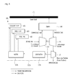
- FIG. 9 is an exemplary embodiment illustrating a variable control type turbo compound system according to the present disclosure.
- FIG. 10 is another exemplary embodiment illustrating a variable control type turbo compound system according to the present disclosure.
- FIG. 11 is a flow chart illustrating a method of operating the variable control type turbo compound system according to the present disclosure.
- FIG. 12 is yet another exemplary embodiment illustrating a mechanical turbo compound system according to the present disclosure.
- FIG. 13 is a flow chart illustrating a method of operating the mechanical turbo compound system of yet another exemplary embodiment according to the present disclosure.
- blow-down turbine which will be described below, is also referred to as a power turbine, and despite the difference in terminology, it is obvious that the blow-down turbine and the power turbine are the same configuration.
- a turbo compound system for a vehicle includes an engine 110 which is an internal combustion engine, a blow-down turbine 120 which is installed at an emission gas discharge side of the engine 110 and recovers waste energy by converting energy of emission gas into mechanical work, a power transmission device 130 a which is connected to the blow-down turbine 120 and operated, and an auxiliary device 150 for a vehicle which is supplied with power directly from the power transmission device 130 a and operated.
- the turbo compound system further includes a turbocharger turbine 111 which is installed at the emission gas discharge side of the engine 110 and converts energy of emission gas into mechanical work, and a turbocharger compressor 112 which is operated by the turbocharger turbine 111 , compresses air for fuel, and supercharges the compressed air into the engine 110 , and the turbo compound system may supply air for fuel using waste energy like the related art.
- a mechanical power transmission device 130 a which includes a transmission 131 a that is installed at an output side of the blow-down turbine 120 , and a speed-reducing gear 132 a that is installed at an output side of the transmission 131 a so as to transfer power to the auxiliary device 150 for a vehicle, is used.
- the transmission 131 a There are two types of methods for the transmission 131 a , such as a method of using a fluid and a direct contact type, and even though any one of the two types may be used, when the fluid type is used through a fluid coupling and the like, power transmission efficiency is slightly lower in comparison with the direct contact type, but matching development and control are easy, and system implementation performance is high.
- the auxiliary device 150 for a vehicle which is used to recover and recycle waste energy of emission gas
- various components of a vehicle may be used as long as the components may recover and recycle waste energy, except for the crank shaft 140 that has a high power load and is a subject to be essentially controlled in a vehicle.
- the auxiliary device 150 for a vehicle is preferably an air conditioner 150 which greatly affects fuel consumption while being operated when the vehicle runs.
- the air conditioner 150 is operated by the mechanical power transmission device 130 a so as to form a refrigerant cycle, and generally includes a compressor, a condenser, an expansion valve, an evaporator, and the like, such that for example, when the compressor is operated by the blow-down turbine 120 , a motor for compression may be operated by the blow-down turbine 120 so as to compress a refrigerant.
- a motor for compression may be operated by the blow-down turbine 120 so as to compress a refrigerant.
- the condenser, the expansion valve, and the evaporator may also be operated by the blow-down turbine 120 in addition to the compressor.
- the present disclosure may operate the compressor of the air conditioner 150 using the blow-down turbine 120 that converts waste energy of emission gas into mechanical work, waste energy may be utilized for the auxiliary device 150 for a vehicle, and the compressor is operated using waste energy without additional fuel consumption, thereby preventing fuel efficiency from deteriorating.
- waste energy is first transferred to the crank shaft 140 , and thereafter, the compressor is operated by the crank shaft 140 , whereas in the present disclosure, mechanical work of the blow-down turbine 120 is directly transferred to the compressor without passing through the crank shaft 140 , thereby preventing output of the crank shaft 140 from being reduced when the air conditioner 150 is operated.
- the compressor is independently operated by the blow-down turbine 120 , when the vehicle is tuned in order to meet emission gas regulation and fuel efficiency target values when the vehicle is developed, additional tuning for preparing for a situation when the air conditioner 150 is operated and related control logic become extraordinarily simplified or unnecessary, thereby saving development costs and period, and preventing a problem that emission gas exceeds an allowed value, which may occur when the air conditioner 150 is operated.
- the air conditioner 150 particularly, the compressor is exemplified above as the auxiliary device 150 for a vehicle that is used to recover and recycle waste energy of emission gas
- the mechanical power transmission device 130 a which includes the transmission 131 a and the speed-reducing gear 132 a , is exemplified as the power transmission device 130 a.
- an electric power transmission device 130 b may also be used, and the electric power transmission device 130 b converts waste energy into electrical energy, and thereafter, allows the air conditioner 150 to be operated.
- the electric power transmission device 130 b includes a generator 131 b which is installed at an output side of the blow-down turbine 120 , and a motor 132 b which is installed at an output side of the generator 131 b and operated by generated electric power, and power of the motor 132 b , which is operated by generated electric power, is transferred to the air conditioner 150 so as to operate the compressor and the like.
- waste energy may be utilized for the auxiliary device 150 for a vehicle without additional fuel consumption, output of the crank shaft 140 is prevented from being reduced when the air conditioner 150 is operated, and additional tuning and related control logic are extraordinarily simplified.
- generated electric power of the generator 131 b is additionally used to charge a battery (not illustrated) of the vehicle so as to start the vehicle, or generated electric power is directly supplied to various electric devices (not illustrated) such as a lighting device or a display device for a vehicle, so as to be utilized in additional various forms, and even though system costs are high compared to the mechanical type, high efficiency may be maintained in a wider operational range.
- auxiliary device for a vehicle which recycles recovered waste energy
- auxiliary machinery that assists driving of the engine.
- a turbo compound system for a vehicle includes an engine 110 which is an internal combustion engine, a blow-down turbine 120 which recovers waste energy by converting energy of emission gas into mechanical work, a power transmission device 130 a which is connected to the blow-down turbine 120 and operated, and an auxiliary device 160 for a vehicle which is supplied with power directly from the power transmission device 130 a and operated.
- the turbo compound system may further include a turbocharger turbine 111 which converts energy of emission gas into mechanical work, and a turbocharger compressor 112 which is operated by the turbocharger turbine 111 , compresses air for fuel, and supercharges the compressed air into the engine 110 .
- a mechanical power transmission device 130 a which includes a transmission 131 a that is installed at an output side of the blow-down turbine 120 , and a speed-reducing gear 132 a that is installed at an output side of the transmission 131 a so as to transfer power to the auxiliary device 150 for a vehicle, is used.
- auxiliary device 160 for a vehicle which is used to recover and recycle waste energy of emission gas
- auxiliary machinery 160 such as a coolant pump 161 , a fuel pump 162 , a fuel fan 163 , and the like, which assists driving of the engine 110 .
- waste energy may be utilized for the auxiliary device 160 for a vehicle, and the auxiliary machinery 160 is operated using waste energy without additional fuel consumption, thereby preventing fuel efficiency from deteriorating.
- auxiliary machinery 160 is independently operated by mechanical work of the blow-down turbine 120 , when the vehicle is tuned at a step of developing the vehicle, additional tuning prepared for when the auxiliary machinery 160 is operated and related control logic become extraordinarily simplified or unnecessary.
- an electric power transmission device 130 b may also be used, and the electric power transmission device 130 b converts waste energy into electrical energy, and thereafter, operates the auxiliary machinery 160 .
- the electric power transmission device 130 b includes a generator 131 b which is installed at an output side of the blow-down turbine 120 , and a motor 132 b which is installed at an output side of the generator and operated by generated electric power, and the auxiliary machinery 160 is operated by power of the motor 132 b which is operated by generated electric power.
- the present disclosure may charge a battery with generated electric power of the generator 131 b , or directly supplies generated electric power to various electric devices such as a lighting device or a display device for a vehicle, thereby further increasing utilization.
- a variable control type turbo compound system for a vehicle includes an engine 110 which is an internal combustion engine, a blow-down turbine 120 which is installed at an emission gas discharge side of the engine 110 , power transmission devices 130 a and 130 b which are connected to the blow-down turbine 120 , a crank shaft 140 which is rotated by the engine 110 , an auxiliary device 150 for a vehicle which is driven by receiving power from the crank shaft 140 and the power transmission devices 130 a and 130 b , and a control unit (not illustrated) which controls power transmitted to the auxiliary device 150 for a vehicle based on an operational condition of the engine 110 .
- the turbo compound system further includes a turbocharger turbine 111 which is installed at the emission gas discharge side of the engine 110 and converts energy of emission gas into mechanical work, and a turbocharger compressor 112 which is operated by the turbocharger turbine 111 , compresses air for fuel, and supercharges the compressed air into the engine 110 , and the turbo compound system may supply air for fuel using waste energy like the related art.
- waste energy of emission gas is recovered and converted into mechanical work (that is, power generation) in the blow-down turbine 120 , power generated in the blow-down turbine 120 is transferred to the auxiliary device 150 for a vehicle through the power transmission devices 130 a and 130 b , and thereby, the configuration may be used as a configuration that operates the auxiliary device 150 for a vehicle together with the crank shaft 140 .
- emission gas energy of the engine 110 is recovered by the blow-down turbine 120 and provided to the auxiliary device 150 for a vehicle, and thus it is not necessary to consume additional fuel in order to operate the auxiliary device 150 for a vehicle, thereby preventing deterioration of fuel efficiency and output reduction.
- the auxiliary device 150 for a vehicle is connected to each of the crank shaft 140 and the power transmission devices 130 a and 130 b so as to be driven by receiving power from the crank shaft 140 and the power transmission devices 130 a and 130 b , and in this case, the control unit controls power, respectively, which is transferred from the crank shaft 140 and the power transmission devices 130 a and 130 b to the auxiliary device 150 for a vehicle based on an operational condition of the engine 110 , thereby stably operating the turbo compound system.
- a mechanical power transmission device 130 a which includes a transmission 131 a that is installed at an output side of the blow-down turbine 120 , and a speed-reducing gear 132 a that is installed at an output side of the transmission 131 a so as to transfer power to the auxiliary device 150 for a vehicle, may be used.
- the transmission 131 a There are two types of methods for the transmission 131 a , such as a method of using a fluid and a direct contact type, and even though any one of the two types may be used, when the fluid type is used through a fluid coupling and the like, power transmission efficiency is slightly lower in comparison with the direct contact type, but matching development and control are easy, and system implementation performance is high.
- an electric power transmission device 130 b which converts waste energy into electrical energy, and thereafter operates the auxiliary device 150 for a vehicle, may also be used.
- the electric power transmission device 130 b includes a generator 131 b which is installed at an output side of the blow-down turbine 120 , and a motor 132 b which is installed at an output side of the generator 131 b , operated by generated electric power, and connected to the auxiliary device 150 for a vehicle.
- generated electric power of the generator 131 b is used to charge a battery of the vehicle so as to start the vehicle, or generated electric power is directly supplied to various electric devices such as a lighting device or a display device for a vehicle, so as to be utilized in additional various forms.
- generated electric power is directly supplied to various electric devices such as a lighting device or a display device for a vehicle, so as to be utilized in additional various forms.
- system costs are high compared to the mechanical type, high efficiency may be maintained in a wider operational range.
- auxiliary device 150 for a vehicle which is used to recover and recycle waste energy of emission gas
- various component of a vehicle may be used as long as the components may recover and recycle waste energy, except for the crank shaft 140 that has a high power load and is a subject to be essentially controlled in a vehicle.
- the auxiliary device 150 for a vehicle is an air conditioner 151 which greatly affects fuel consumption while being operated when the vehicle runs, and the air conditioner 151 includes a compressor, a condenser, an expansion valve, an evaporator, and the like such that when the compressor is operated by the blow-down turbine 120 , a motor for compression is operated by the blow-down turbine 120 so as to compress a refrigerant.
- the condenser, the expansion valve, and the evaporator may also be operated by the blow-down turbine 120 in addition to the compressor.
- auxiliary machine such as a coolant pump 152 , a fuel pump 153 , a fuel fan 154 , and the like, which assists driving of the engine 110 , may also be used.
- crank shaft 140 is connected to the auxiliary device 150 for a vehicle through a first actuator (Actuator 1)
- the blow-down turbine 120 is connected to the power transmission devices 130 a and 130 b through a second actuator (Actuator 2)
- the power transmission devices 130 a and 130 b are connected to the auxiliary device 150 for a vehicle through a third actuator (Actuator 3).
- an environment is provided to allow each of the crank shaft 140 and the blow-down turbine 120 to operate the auxiliary device 150 for a vehicle, and to allow the control unit to control power transmission of each of the crank shaft 140 and the blow-down turbine 120 .
- the control unit may be integrally provided in an electronic controller unit (ECU) or an electronic power controller system (EPOS), which is equipped in various vehicles including heavy equipment, or may be modularized and separately provided, and connection states of the first actuator (Actuator 1) to the third actuator (Actuator 3) are controlled by the control unit, respectively.
- ECU electronic controller unit
- EPOS electronic power controller system
- connection state is generally divided into ‘connection’ and ‘connection release’.
- connection is divided into various steps of ‘connections’ like an operation of shifting gears so as to adjust torque or speed, which is transferred to the auxiliary device 150 for a vehicle, in several steps, and connection degrees may be controlled, respectively.
- control unit preferably divides a case in which the engine 110 is in a variable (transient) operational state and a case in which the engine 110 is in the other operational states (for example, a constant-speed operational state), and controls power, respectively, which is transferred from the crank shaft 140 and the power transmission devices 130 a and 130 b to the auxiliary device 150 for a vehicle.
- the blow-down turbine 120 depends on thermal energy of emission gas of engine 110 , and in this case, the thermal energy of emission gas is varied based on an operational condition of the vehicle (engine), and when thermal energy of emission gas is varied for every moment under a variable operational condition, power, which is supplied from the blow-down turbine 120 to the auxiliary device 150 for a vehicle, is also varied.
- the case in which the vehicle is in a variable operational state and the case in which the vehicle is in the other operational states are divided, and power, which is transferred from the crank shaft 140 and the power transmission devices 130 a and 130 b to the auxiliary device 150 for a vehicle, is controlled for each operational state, thereby allowing the turbo compound system to be stably operated.
- the present disclosure operates the auxiliary device 150 for a vehicle through both the crank shaft 140 and the power transmission devices 130 a and 130 b , or operates the auxiliary device 150 for a vehicle through any one of the crank shaft 140 and the power transmission devices 130 a and 130 b , thereby allowing the turbo compound system to be always and stably operated.
- the first actuator (Actuator 1) is connected to the auxiliary device 150 for a vehicle so as to operate the auxiliary device 150 for a vehicle only through the crank shaft 140 , and the connections of the second actuator (Actuator 2) and the third actuator (Actuator 3) to the auxiliary device 150 for a vehicle are released.
- the connection of the first actuator (Actuator 1) to the auxiliary device 150 for a vehicle is released so as to operate the auxiliary device 150 for a vehicle only through the blow-down turbine 120 , and the second actuator (Actuator 2) and the third actuator (Actuator 3) are connected to the auxiliary device 150 for a vehicle.
- both the second actuator (Actuator 2) and the third actuator (Actuator 3) may be connected to or disconnected from the auxiliary device 150 for a vehicle as described above, but additionally, the second actuator (Actuator 2) may be controlled so as to be connected to the auxiliary device 150 for a vehicle, and the third actuator (Actuator 3) may be controlled so as to be disconnected from the auxiliary device 150 for a vehicle.
- variable control type turbo compound system Accordingly, a method of operating the variable control type turbo compound system according to the present disclosure will be described with reference to FIG. 11 .
- the control unit monitors an operational state of the vehicle (engine), and determines whether the operational state is the constant-speed operational state (S 110 ).
- the control unit determines whether the operational state is the constant-speed operational state (S 110 ).
- a manner in which the monitoring of the operational state is directly performed by the control unit a manner in which the monitoring of the operation state is performed by the ECU or the EPOS, and thereafter a result thereof is provided to the control unit may also be used.
- the second actuator (Actuator 2) and the third actuator (Actuator 3) are connected to an accessory device for a vehicle (S 121 and S 122 ), and the connection of the first actuator (Actuator 1) to the accessory device for a vehicle is released (S 123 ).
- the accessory device for a vehicle is operated only through the blow-down turbine 120 , thereby operating the accessory device for a vehicle without additional fuel consumption.
- the first actuator (Actuator 1) is connected to the accessory device for a vehicle (S 131 ), and the connections of the second actuator (Actuator 2) and the third actuator (Actuator 3) to the accessory device for a vehicle are released (S 132 and S 133 ).
- the accessory device for a vehicle is operated only through the crank shaft 140 , thereby preventing an operation of the turbo compound system from becoming unstable due to variation in the emission gas energy.
- the accessory device for a vehicle may be simultaneously operated through both the blow-down turbine 120 and the crank shaft 140 , and in this case, each connection degree may be controlled so as to be minutely adjusted for each step.
- a turbo compound system includes an engine 110 which is an internal combustion engine, a blow-down turbine 120 which is installed at an emission gas discharge side of the engine 110 , a power transmission device 130 a which is connected to the blow-down turbine 120 , a crank shaft 140 which is rotated by the engine 110 , a bypass line 170 which is provided to bypass emission gas, which flows into the blow-down turbine 120 , based on an operational condition of the engine 110 , and a bypass valve 171 which is provided at an upstream portion of the bypass line 170 so as to control a flow of emission gas.
- the turbo compound system further includes a turbocharger turbine 111 which is installed at the emission gas discharge side of the engine 110 and converts energy of emission gas into mechanical work, and a turbocharger compressor 112 which is operated by the turbocharger turbine 111 , compresses air for fuel, and supercharges the compressed air into the engine 110 , and the turbo compound system may supply air for fuel using waste energy like the related art.
- waste energy of emission gas is recovered and converted into mechanical work (that is, power generation) in the blow-down turbine 120 , power generated in the blow-down turbine 120 is transferred to the crank shaft 140 through the power transmission device 130 a.
- a mechanical power transmission device 130 a which includes a transmission 131 a that is installed at an output side of the blow-down turbine 120 , and a speed-reducing gear 132 a that is installed at an output side of the transmission 131 a so as to transfer power to the crank shaft 140 , may be used.
- the transmission 131 a There are two types of methods for the transmission 131 a , such as a method of using a fluid and a direct contact type, and even though any one of the two types may be used, when the fluid type is used through a fluid coupling and the like, power transmission efficiency is slightly lower in comparison with the direct contact type, but matching development and control are easy, and system implementation performance is high.
- an electric power transmission device which converts waste energy into electrical energy, and thereafter operates the auxiliary device for a vehicle and the like, may also be used.
- the electric power transmission device includes a generator which is installed at an output side of the blow-down turbine 120 , and a motor which is installed at an output side of the generator, operated by generated electric power, and connected to the auxiliary device for a vehicle.
- generated electric power of the generator is used to charge a battery of the vehicle so as to start the vehicle, or generated electric power is directly supplied to various electric devices such as a lighting device or a display device for a vehicle, so as to be utilized in additional various forms.
- various electric devices such as a lighting device or a display device for a vehicle, so as to be utilized in additional various forms.
- system costs are high compared to the mechanical type, high efficiency may be maintained in a wider operational range.
- auxiliary device for a vehicle which is used to recover and recycle waste energy of emission gas
- various components of a vehicle may be used as long as the components may recover and recycle waste energy, except for the crank shaft 140 that has a high power load and is a subject to be essentially controlled in a vehicle.
- the auxiliary device for a vehicle is an air conditioner which greatly affects fuel consumption while being operated when the vehicle runs, and the air conditioner includes a compressor, a condenser, an expansion valve, an evaporator, and the like such that when the compressor is operated by the blow-down turbine 120 , a motor for compression is operated by the blow-down turbine 120 so as to compress a refrigerant.
- the condenser, the expansion valve, and the evaporator may also be operated by the blow-down turbine 120 in addition to the compressor.
- auxiliary machine such as a coolant pump, a fuel pump, a fuel fan, and the like, which assists driving of the engine, may also be used.
- the bypass line 170 which is provided to bypass emission gas that flows into the blow-down turbine, is connected to front and rear sides of the blow-down turbine.
- bypass valve 171 is provided at the upstream portion of the bypass line 170 so as to control a flow of emission gas, and as the bypass valve 171 , various valves such as a mechanical or electronic proportional valve may be used.
- the turbo compound system may further include a first control unit for controlling the bypass valve 171 . That is, based on an operational condition of the engine, an operation of opening and closing the bypass valve 171 is controlled.
- a flow rate of emission gas, which is bypassed by the bypass line 170 is adjusted so that the mechanical turbo compound system may obtain optimum efficiency in all operational regions.
- an actuator 180 is provided between the crank shaft 140 and the speed-reducing gear 132 a .
- the actuator 180 may connect power supplied from the blow-down turbine 120 to the crank shaft 140 , or may release the connection of power to the crank shaft 140 .
- the actuator 180 releases the engagement in a state like the low-speed and low-load state, and makes the engagement in a state like a high-speed and high-load state, thereby improving fuel efficiency.
- the turbo compound system may further include a second control unit for controlling the actuator 180 . That is, based on an operational condition of the engine, an operation of the actuator 180 is controlled.
- crank shaft 140 may be connected to the speed-reducing gear 132 a through the actuator 180
- the blow-down turbine 120 may be connected to the power transmission device 130 a through the second actuator (Actuator 2)
- the power transmission device 130 a may be connected to the auxiliary device for a vehicle through a third actuator (Actuator 3).
- an environment is provided to allow each of the crank shaft 140 and the blow-down turbine 120 to operate the auxiliary device for a vehicle, and to allow the second control unit to control power transmission of each of the crank shaft 140 and the blow-down turbine 120 .
- the first control unit and the second control unit may be integrally provided in an electronic controller unit (ECU) or an electronic power controller system (EPOS), which is equipped in various vehicles including heavy equipment, or may be modularized and separately provided, and a connection state of the actuator 180 and the bypass valve 171 are controlled by the control units, respectively.
- ECU electronic controller unit
- EPOS electronic power controller system
- connection state is generally divided into ‘connection’ and ‘connection release’.
- connection is divided into various steps of ‘connections’ like an operation of shifting gears so as to adjust torque or speed, which is transferred to the auxiliary device for a vehicle, in several steps, and connection degrees may be controlled, respectively.
- first control unit and the second control unit preferably divide a case in which the engine 110 is in a variable (transient) operational state and a case in which the engine 110 is in the other operational states (for example, a constant-speed operational state), and control power, respectively, which is transferred from the crank shaft 140 and the power transmission device 130 a to the auxiliary device for a vehicle.
- the blow-down turbine 120 depends on thermal energy of emission gas of engine 110 , and in this case, the thermal energy of emission gas is varied based on an operational condition of the vehicle (engine), and when thermal energy of emission gas is varied for every moment, power, which is supplied from the blow-down turbine 120 to the power transmission device 130 a , is also varied.
- power which is transmitted from the power transmission device 130 a to the crank shaft 140 and the auxiliary device for a vehicle, is controlled based on an operational state, respectively, thereby allowing the turbo compound system to be stably operated.
- the present disclosure connects the crank shaft 140 and the power transmission device 130 a and releases the connection of the crank shaft 140 and the power transmission device 130 a , and bypasses emission gas, which flows into the blow-down turbine 120 , so as to adjust a flow rate of emission gas, thereby allowing the turbo compound system to be always and stably operated.
- the connection of the actuator 180 is released so that only the crank shaft 140 is operated, and the bypass valve 171 is opened to bypass emission gas discharged from the engine 110 to the bypass line 170 .
- an amount of open degree of the bypass valve 171 may be operated in an on/off state, and a partial amount may be bypassed depending on the circumstances.
- the bypass valve 171 is closed so that emission gas discharged from the engine 110 flows into the blow-down turbine 120 without being bypassed to the bypass line 170 .
- the actuator 180 which is connected between the crank shaft 140 and the power transmission device 130 a , is connected to transfer power of the power transmission device 130 a to the crank shaft 140 .
- FIG. 13 is a flow chart explaining a process in which the turbo compound system according to the present disclosure selects operations of the bypass valve 171 and the actuator 180 based on an operational condition of the engine 110 .
- an operational state of the vehicle is monitored, and it is determined whether the operational state is the constant-speed operational state or the low-speed and low-load operational state (S 110 ).
- the monitoring of the operational state is directly performed, a manner in which the monitoring of the operation state is performed by the ECU or the EPOS, and thereafter a result thereof is provided may also be used.
- the bypass valve 171 is closed so that emission gas flows into the blow-down turbine 120 , and the engagement of the actuator 180 is maintained so that power of the power transmission device 130 a is transferred to the crank shaft 140 .
- the accessory device for a vehicle may be simultaneously operated through both the blow-down turbine 120 and the crank shaft 140 , and in this case, each connection degree may be controlled so as to be minutely adjusted for each step.
- the turbo compound system for a vehicle may be used for a turbo compound system for a vehicle which may recover emission gas energy and provide the energy to various auxiliary devices for a vehicle.
Landscapes
- Engineering & Computer Science (AREA)
- Mechanical Engineering (AREA)
- General Engineering & Computer Science (AREA)
- Chemical & Material Sciences (AREA)
- Combustion & Propulsion (AREA)
- Supercharger (AREA)
- Physics & Mathematics (AREA)
- Thermal Sciences (AREA)
Abstract
Description
-
- 110: Engine
- 111: Turbocharger turbine
- 112: Turbocharger compressor
- 120: Blow-down turbine
- 130 a: Mechanical power transmission device
- 131 a: Transmission
- 132 a: Speed-reducing gear
- 130 b: Electric power transmission device
- 131 b: Generator
- 132 b: Motor
- 140: Crank shaft
- 150, 160: Auxiliary device for vehicle
- 150: Air conditioner
- 160: Auxiliary machinery
Claims (6)
Applications Claiming Priority (7)
| Application Number | Priority Date | Filing Date | Title |
|---|---|---|---|
| KR10-2012-0007732 | 2012-01-26 | ||
| KR10-2012-0007729 | 2012-01-26 | ||
| KR1020120007732A KR101887694B1 (en) | 2012-01-26 | 2012-01-26 | Variable control type turbo compound system for vehicle |
| KR1020120007729A KR20130086776A (en) | 2012-01-26 | 2012-01-26 | Turbo compound system for vehicle |
| KR10-2012-0028071 | 2012-03-20 | ||
| KR1020120028071A KR20130106495A (en) | 2012-03-20 | 2012-03-20 | Turbo compound system with improved structure |
| PCT/KR2013/000587 WO2013111980A1 (en) | 2012-01-26 | 2013-01-25 | Turbo compound system for vehicle |
Publications (2)
| Publication Number | Publication Date |
|---|---|
| US20150037178A1 US20150037178A1 (en) | 2015-02-05 |
| US9884538B2 true US9884538B2 (en) | 2018-02-06 |
Family
ID=48873663
Family Applications (1)
| Application Number | Title | Priority Date | Filing Date |
|---|---|---|---|
| US14/374,791 Active 2034-04-07 US9884538B2 (en) | 2012-01-26 | 2013-01-25 | Turbo compound system for vehicle |
Country Status (2)
| Country | Link |
|---|---|
| US (1) | US9884538B2 (en) |
| WO (1) | WO2013111980A1 (en) |
Families Citing this family (6)
| Publication number | Priority date | Publication date | Assignee | Title |
|---|---|---|---|---|
| JP6434285B2 (en) | 2013-12-04 | 2018-12-05 | 三菱重工業株式会社 | Control device for supercharging system |
| JP6234198B2 (en) | 2013-12-04 | 2017-11-22 | 三菱重工業株式会社 | Turbocharger device |
| JP6351962B2 (en) | 2013-12-04 | 2018-07-04 | 三菱重工業株式会社 | Turbocharger control device |
| JP6294646B2 (en) * | 2013-12-04 | 2018-03-14 | 三菱重工業株式会社 | Turbo compound system controller |
| JP6377340B2 (en) | 2013-12-04 | 2018-08-22 | 三菱重工業株式会社 | Control device for supercharging system |
| US10035511B2 (en) * | 2015-07-27 | 2018-07-31 | Cummins Inc. | Method and system for controlling operation of an engine powered device having cyclical duty cycles |
Citations (12)
| Publication number | Priority date | Publication date | Assignee | Title |
|---|---|---|---|---|
| US3979913A (en) * | 1975-01-20 | 1976-09-14 | Yates Harold P | Method and system for utilizing waste energy from internal combustion engines as ancillary power |
| JPS6255420A (en) | 1985-09-04 | 1987-03-11 | Yanmar Diesel Engine Co Ltd | Power recovery device for turbo compound engine |
| US5329770A (en) * | 1993-05-06 | 1994-07-19 | Ward Michael S | Exhaust gas turbine drive system for engine accessories |
| JPH07102987A (en) | 1993-10-04 | 1995-04-18 | Isuzu Motors Ltd | Exhaust energy recovery device |
| US6470680B1 (en) * | 2000-03-15 | 2002-10-29 | Charl E Janeke | Manifold alternator generator |
| US7047743B1 (en) * | 2005-03-14 | 2006-05-23 | Deere & Company | Electric turbo compound configuration for an engine/electric generator system |
| JP2006299938A (en) | 2005-04-21 | 2006-11-02 | Hino Motors Ltd | Turbo compound system |
| JP2007303295A (en) | 2006-05-09 | 2007-11-22 | Hino Motors Ltd | Method and apparatus for controlling turbo compound engine |
| US7434389B2 (en) * | 2006-03-08 | 2008-10-14 | Caterpillar Inc. | Engine system and method of providing power therein |
| US8261550B2 (en) * | 2006-12-19 | 2012-09-11 | Renault Trucks | Power unit for an automotive vehicle and vehicle including such a power unit |
| US8302398B2 (en) * | 2008-08-29 | 2012-11-06 | Deere & Company | Work machine with drive train coupled turbo compounding |
| US8584460B2 (en) * | 2008-11-19 | 2013-11-19 | Volvo Lastvagnar Ab | Method and arrangement for reducing an NOx content in the exhaust gas of an internal combustion engine in a vehicle |
-
2013
- 2013-01-25 US US14/374,791 patent/US9884538B2/en active Active
- 2013-01-25 WO PCT/KR2013/000587 patent/WO2013111980A1/en not_active Ceased
Patent Citations (12)
| Publication number | Priority date | Publication date | Assignee | Title |
|---|---|---|---|---|
| US3979913A (en) * | 1975-01-20 | 1976-09-14 | Yates Harold P | Method and system for utilizing waste energy from internal combustion engines as ancillary power |
| JPS6255420A (en) | 1985-09-04 | 1987-03-11 | Yanmar Diesel Engine Co Ltd | Power recovery device for turbo compound engine |
| US5329770A (en) * | 1993-05-06 | 1994-07-19 | Ward Michael S | Exhaust gas turbine drive system for engine accessories |
| JPH07102987A (en) | 1993-10-04 | 1995-04-18 | Isuzu Motors Ltd | Exhaust energy recovery device |
| US6470680B1 (en) * | 2000-03-15 | 2002-10-29 | Charl E Janeke | Manifold alternator generator |
| US7047743B1 (en) * | 2005-03-14 | 2006-05-23 | Deere & Company | Electric turbo compound configuration for an engine/electric generator system |
| JP2006299938A (en) | 2005-04-21 | 2006-11-02 | Hino Motors Ltd | Turbo compound system |
| US7434389B2 (en) * | 2006-03-08 | 2008-10-14 | Caterpillar Inc. | Engine system and method of providing power therein |
| JP2007303295A (en) | 2006-05-09 | 2007-11-22 | Hino Motors Ltd | Method and apparatus for controlling turbo compound engine |
| US8261550B2 (en) * | 2006-12-19 | 2012-09-11 | Renault Trucks | Power unit for an automotive vehicle and vehicle including such a power unit |
| US8302398B2 (en) * | 2008-08-29 | 2012-11-06 | Deere & Company | Work machine with drive train coupled turbo compounding |
| US8584460B2 (en) * | 2008-11-19 | 2013-11-19 | Volvo Lastvagnar Ab | Method and arrangement for reducing an NOx content in the exhaust gas of an internal combustion engine in a vehicle |
Non-Patent Citations (1)
| Title |
|---|
| Search Report dated May 13, 2013 and written in Korean with English translation for International Patent Application No. PCT/KR2013/000587 filed Jan. 25, 2012, 5 pages. |
Also Published As
| Publication number | Publication date |
|---|---|
| WO2013111980A1 (en) | 2013-08-01 |
| US20150037178A1 (en) | 2015-02-05 |
Similar Documents
| Publication | Publication Date | Title |
|---|---|---|
| US10330030B2 (en) | Hybrid system comprising a supercharging system and method for operation | |
| US7958873B2 (en) | Open loop Brayton cycle for EGR cooling | |
| US8141360B1 (en) | Hybrid gas turbine and internal combustion engine | |
| US9884538B2 (en) | Turbo compound system for vehicle | |
| US10066532B2 (en) | Electric supercharging device utilizing waste heat of internal combustion engine and power supplying method thereof | |
| EP2886824B1 (en) | Improved turbocompound scheme, in particular in the field of industrial vehicles | |
| US20140208745A1 (en) | Control strategy for an engine | |
| EP1801386A1 (en) | An arrangement at an internal combustion engine | |
| JP2013509526A (en) | Control method for engine | |
| US20120210952A1 (en) | Motor vehicle with a combustion engine, and method of operating a combustion engine | |
| US11007998B1 (en) | Hybrid vehicle | |
| CN104454137A (en) | Engine device | |
| CN113202643B (en) | System with energy recovery device and control method | |
| US7152393B2 (en) | Arrangement for utilizing the throttle energy of an internal combustion engine | |
| KR20130106495A (en) | Turbo compound system with improved structure | |
| CN108757161B (en) | Engine exhaust energy treatment method and system for hybrid power system | |
| KR101887694B1 (en) | Variable control type turbo compound system for vehicle | |
| JP2002168201A (en) | Engine driven hydraulic system | |
| US20190048750A1 (en) | Dual mode waste heat recovery expander and control method | |
| CN222276788U (en) | Engine systems and automobiles | |
| CN112031928A (en) | Mechanical turbocharging system and method | |
| CN100585142C (en) | internal combustion engine | |
| WO2013159299A1 (en) | Brayton cycle-based waste heat utilization system and engine having same | |
| CN114041005B (en) | Internal combustion engine system, method for controlling internal combustion engine system, control circuit and vehicle | |
| CN119754925A (en) | Electric assisted turbocharging system and control method, and vehicle |
Legal Events
| Date | Code | Title | Description |
|---|---|---|---|
| AS | Assignment |
Owner name: DOOSAN INFRACORE CO., LTD., KOREA, REPUBLIC OF Free format text: ASSIGNMENT OF ASSIGNORS INTEREST;ASSIGNOR:WANG, TAE JOONG;REEL/FRAME:033478/0365 Effective date: 20140723 |
|
| STCF | Information on status: patent grant |
Free format text: PATENTED CASE |
|
| MAFP | Maintenance fee payment |
Free format text: PAYMENT OF MAINTENANCE FEE, 4TH YEAR, LARGE ENTITY (ORIGINAL EVENT CODE: M1551); ENTITY STATUS OF PATENT OWNER: LARGE ENTITY Year of fee payment: 4 |
|
| AS | Assignment |
Owner name: HD HYUNDAI INFRACORE CO., LTD., KOREA, REPUBLIC OF Free format text: CHANGE OF NAME;ASSIGNOR:HYUNDAI DOOSAN INFRACORE CO., LTD.;REEL/FRAME:065761/0957 Effective date: 20230327 Owner name: HYUNDAI DOOSAN INFRACORE CO., LTD., KOREA, REPUBLIC OF Free format text: CHANGE OF NAME;ASSIGNOR:DOOSAN INFRACORE CO., LTD.;REEL/FRAME:065761/0942 Effective date: 20210910 |
|
| AS | Assignment |
Owner name: TCW ASSET MANAGEMENT COMPANY LLC, AS COLLATERAL AGENT, MASSACHUSETTS Free format text: SECURITY INTEREST;ASSIGNORS:LIFELINE SYSTEMS COMPANY;ANELTO, INC.;100PLUS, INC.;AND OTHERS;REEL/FRAME:069164/0414 Effective date: 20241011 |
|
| MAFP | Maintenance fee payment |
Free format text: PAYMENT OF MAINTENANCE FEE, 8TH YEAR, LARGE ENTITY (ORIGINAL EVENT CODE: M1552); ENTITY STATUS OF PATENT OWNER: LARGE ENTITY Year of fee payment: 8 |