US9883743B2 - Firearm lock shroud - Google Patents
Firearm lock shroud Download PDFInfo
- Publication number
- US9883743B2 US9883743B2 US15/162,434 US201615162434A US9883743B2 US 9883743 B2 US9883743 B2 US 9883743B2 US 201615162434 A US201615162434 A US 201615162434A US 9883743 B2 US9883743 B2 US 9883743B2
- Authority
- US
- United States
- Prior art keywords
- firearm
- lock
- side member
- shroud
- firearm lock
- Prior art date
- Legal status (The legal status is an assumption and is not a legal conclusion. Google has not performed a legal analysis and makes no representation as to the accuracy of the status listed.)
- Active
Links
Images


Classifications
-
- A—HUMAN NECESSITIES
- A47—FURNITURE; DOMESTIC ARTICLES OR APPLIANCES; COFFEE MILLS; SPICE MILLS; SUCTION CLEANERS IN GENERAL
- A47B—TABLES; DESKS; OFFICE FURNITURE; CABINETS; DRAWERS; GENERAL DETAILS OF FURNITURE
- A47B81/00—Cabinets or racks specially adapted for other particular purposes, e.g. for storing guns or skis
- A47B81/005—Devices for storing or displaying rifles, guns, pistols or elongated objects such as fishing rods storing fishing rods
-
- B—PERFORMING OPERATIONS; TRANSPORTING
- B60—VEHICLES IN GENERAL
- B60R—VEHICLES, VEHICLE FITTINGS, OR VEHICLE PARTS, NOT OTHERWISE PROVIDED FOR
- B60R7/00—Stowing or holding appliances inside vehicle primarily intended for personal property smaller than suit-cases, e.g. travelling articles, or maps
- B60R7/08—Disposition of racks, clips, holders, containers or the like for supporting specific articles
- B60R7/14—Disposition of racks, clips, holders, containers or the like for supporting specific articles for supporting weapons
-
- F—MECHANICAL ENGINEERING; LIGHTING; HEATING; WEAPONS; BLASTING
- F41—WEAPONS
- F41A—FUNCTIONAL FEATURES OR DETAILS COMMON TO BOTH SMALLARMS AND ORDNANCE, e.g. CANNONS; MOUNTINGS FOR SMALLARMS OR ORDNANCE
- F41A17/00—Safety arrangements, e.g. safeties
- F41A17/46—Trigger safeties, i.e. means for preventing trigger movement
- F41A17/54—Protecting-caps for trigger guards; Trigger locking pieces mounted on, or within, the trigger guard
Definitions
- This application relates to firearm storage, and in particular to a shroud that provides additional security to a locked firearm.
- Described below are implementations of a firearm shroud that addresses potential problems with conventional firearm locks.
- a firearm lock shroud for a firearm lock comprises a first side member and a second side member.
- the first side member is positionable adjacent the firearm lock.
- the second side member is positionable adjacent the firearm lock and spaced apart from the first side member.
- the first and second side members define a firearm receiving space therebetween for receiving a firearm.
- the first and second side members extend over an area to cover at least a trigger area of a firearm received in the firearm receiving space and locked by the firearm lock to prevent unauthorized access to the trigger area.
- the first and second side members extend to cover a take-down pin area of the firearm received in the firearm receiving space to prevent unauthorized access to a take-down pin for the firearm.
- the first and second side members extend to cover a magazine area of the firearm received in the firearm receiving space to prevent unauthorized access to a magazine for the firearm.
- the firearm lock shroud comprises a bracket connected to the first side member and to the second side member, and the bracket defines mounting holes and/or a mounting surface for mounting the firearm lock. In some implementations, the bracket defines rear and upper surfaces when the firearm lock shroud is in an installed position.
- the shroud is adjustably positionable in at least a vertical direction by fasteners adjustably coupling the shroud to a stationary track.
- the firearm lock shroud comprises an anti-lift bracket that extends from one end positioned at the first side member, over the firearm lock and to a second end positioned at the second side member.
- the firearm lock shroud comprises an anti-lift bracket tab adjustably coupled to the anti-lift bracket, wherein the anti-lift bracket tab is adjustably positionable to contact a firearm with the firearm lock in the locked position around a firearm within the firearm receiving space.
- the firearm lock shroud comprises at least one spacer member mounted to an inner surface of at least one of the first side member or the second side member.
- FIG. 1A is a perspective view of a firearm lock assembly for two firearms and having a firearm lock shroud for one of the two firearms.
- FIG. 1B is a perspective view of an exemplary firearm that can be stored and locked within the firearm lock assembly of FIG. 1 .
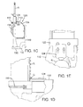
- FIG. 1C is a side elevation of the firearm in the firearm lock assembly (with the second firearm removed for clarity).
- FIG. 1D is a magnified view of a portion of the assembly shown in FIG. 1C .
- FIG. 1E is a top plan view of the approximate portion of the assembly shown in FIG. 1D .
- FIG. 2 is an exploded perspective view of the firearm lock assembly of FIG. 1A with the two firearms omitted for clarity.
- FIGS. 3-6 are perspective, side elevation, front elevation and top plan views, respectively, of the firearm lock shroud.
- FIG. 7 is a perspective view of a first side member of the firearm lock shroud.
- FIG. 8A is a perspective view of a second side member of the firearm lock shroud.
- FIG. 8B is a perspective view of the first and second side members assembled together.
- FIG. 9 is a perspective view of an upper bracket of the firearm lock shroud.
- FIG. 10 is a perspective view of an anti-lift bracket base of the firearm lock shroud.
- FIG. 11 is a perspective view of an anti-lift bracket tab of the firearm lock shroud.
- FIG. 12 is a perspective view of a butt holder bracket.
- FIG. 13 is a perspective view of a rail floor bracket.
- FIG. 14 is a perspective view of a second butt holder bracket.
- FIGS. 15A and 15B are perspective and side elevation views of a second lock bracket.
- FIGS. 16A, 16B and 16C are perspective, top plan and side elevation views of a first butt holder.
- FIGS. 17A, 17B and 17C are perspective, top plan and side elevation views of a second butt holder.
- FIGS. 18A, 18B and 18C are side elevation, top plan and end elevation views of a spacer.
- FIG. 19 is a perspective view of a filler plate.
- FIG. 20 is an exploded perspective view of a firearm lock assembly having a modified firearm lock shroud.
- FIGS. 21-24 are perspective, side elevation, front elevation and top plan views, respectively, of the firearm lock shroud of FIG. 20 .
- FIG. 25 is a perspective view of a first side member of the firearm lock shroud of FIG. 20 .
- FIG. 26 is a perspective view of a second side member of the firearm lock shroud of FIG. 20 .
- FIG. 27 is a perspective view of an upper bracket of the firearm lock shroud of FIG. 20 .
- FIG. 28 is a perspective view of a bracket support of the firearm lock shroud of FIG. 20 .
- FIG. 29 is a side elevation view of the second side member of FIG. 26 with a firearm lock, upper bracket and bracket support installed.
- FIG. 30 is a top plan view of the second side member and other components of FIG. 29 .
- Described below are embodiments of a firearm lock shroud and associated vehicle firearm lock assembly typically used in a vehicle.
- a rifle R is secured in an upright position with a lock 110 .
- the lock 110 contacts or extends around the rifle R in the region of its forearm.
- a new guard or shroud 120 is positioned adjacent the lock and configured to prevent tampering with the rifle R, including when the rifle R is in its stored and locked position as shown.
- the shroud 120 extends along the rifle R to cover one or more its trigger T, takedown pin P and magazine M ( FIG. 1B ).
- the shroud 120 extends along both sides of the rifle R, as well as in the area between the lock 110 and a rail 140 to which the shroud and lock are adjustably coupled, as described below in greater detail.
- the lock 110 is sometimes referred to as a Universal Lock.
- a butt of the rifle R is received in a butt holder 130 .
- the butt holder 130 is supported by a butt holder bracket 132 , which is also adjustably coupled to the rail 140 .
- there is a shotgun S secured in an upright position by a second lock 150 which is attached by a second lock bracket 152 to the rail 140 .
- a butt of the shotgun S is received in a second butt holder 160 , which is supported by a second butt holder bracket 162 .
- the rail 140 can have one or more tracks to receive fasteners for adjustably coupling components.
- an anti-lift bracket base 122 and an anti-lift bracket tab 124 that is coupled to the anti-lift bracket base 122 .
- the anti-lift bracket base 122 and anti-lift bracket tab 124 are adjustably positioned to contact or cooperate with the rifle R, such as to eliminate excess play when the rifle R is positioned as shown in FIG. 1A with the lock 110 in the locked position.
- the anti-lift bracket base and anti-lift bracket tab can be moved laterally to contact the rifle R or otherwise prevent it from being lifted, manipulated and/or rotated.
- the anti-lift bracket tab 124 can be positioned so that it is received in a groove G or recess of the firearm R.
- a side elevation view of the rifle R received and locked in the shroud 120 is shown in FIG. 1C .
- FIG. 1D is a magnified view of a portion of FIG. 1C in elevation showing the anti-lift bracket tab 124 positioned above the lock 110 and to extend into a groove G in the forearm area of the rifle R.
- FIG. 1E shows a top plan view of approximately the same portion as FIG. 1D .
- the rifle R cannot be displaced vertically relative to the lock 110 by any appreciable distance, and thus is more secure from tampering efforts.
- the groove G is one of a series of grooves formed in an accessories rail with which the firearm R is typically equipped ( FIGS. 1C and 1D ).
- the shroud and lock assembly can be configured oppositely, i.e., the assembly can have a groove or recess configured to receive a corresponding protrusion on the firearm R.
- FIG. 2 is an exploded perspective view of the vehicle firearm lock assembly 100 of FIG. 1 , except that the rifle R and the shotgun S have been omitted for clarity.
- FIGS. 3-11 are additional views of the shroud and its components.
- the shroud 120 has a first side member 126 and an opposite second side member 128 spaced apart from the side member 126 .
- the side members 126 , 128 can be coupled to the upper bracket 134 with fasteners 146 .
- At least some of the fasteners 146 can be tamper-resistant fasteners, which are defined herein to include fasteners having an uncommon or proprietary head configuration.
- the shroud 120 can have optional spacers 136 mounted along one or more internal surfaces to help guide the rifle into position when it is being inserted into the shroud and to protect the rifle from damage, e.g., such as scratches and/or other damage.
- the side member 126 has a bent outward tab 138
- the side member 128 has a bent inward tab 144 .
- the tabs 138 , 144 define an opening into which the rifle R is inserted.
- the tabs and other structure defining the leading edges of the opening can be modified to suit the particular requirements of the location of the vehicle firearm lock assembly and/or the rifle R, such as where the assembly is mounted and what other structural elements may be present, as well as other circumstances.
- the side members 126 , 128 can be formed from separate components that are joined together.
- the side member 128 can be formed with a back flange 180 and a base flange 182 that extend approximately perpendicular to the side member's major inner and outer surfaces at the leading edge of the side member 128 , and adjacent the bent inward tab 144 , there can be a curved edge 184 extending from an area of the base flange 182 to the bent inward tab 144 .
- the side member 128 can be formed with a notch 186 .
- the side member 126 can be formed with a base flange 170 extending approximately perpendicular to the major inner and outer surfaces of the side member 126 .
- the side member 126 can have a recessed edge 172 adjacent an upper end of the bent outward tab 138 .
- the recessed edge 172 can join a notch 174 as shown.
- the upper bracket 134 that is shaped to fit between the side members 126 , 128 can have a back flange 190 , an angled flange 192 , an upper flange 194 , a mounting flange 196 and a perpendicular mounting flange 198 .
- various types of firearm locks including the lock 110 , can be secured to the upper bracket 134 at the mounting flange 196 and/or the mounting flange 198 , e.g., using fasteners, including tamper-resistant fasteners as discussed above.
- FIG. 10 is a perspective view of the anti-lift bracket base 122
- FIG. 11 is a perspective view of the associated anti-lift bracket tab 124 .
- the anti-lift bracket base 122 is positioned to surround the firearm lock 110 on three of its sides and to be attached to the side member 126 and side member 128 with fasteners.
- the anti-lift bracket tab 124 is adjustably coupled to the anti-lift bracket base 122 such that it can be positioned to contact the rifle R and to prevent the rifle R from being lifted when it is in the secured and locked positioned within the firearm lock 110 as best shown in FIG. 1 .
- FIG. 12 is a perspective view of the butt holder bracket 132 .
- FIG. 13 is a perspective view of a rail floor bracket 142 , also shown in FIG. 2 , with which the rail 140 can be secured, such as to a floor of the vehicle.
- FIG. 14 is a perspective view of a second butt holder bracket 162 .
- FIGS. 15A and 15B are perspective and side views of a second lock bracket 152 by which the second lock 150 is secured to the rail 140 .
- the rail 140 has a series of slots along with the various components can be adjustably positioned to allow for secure attachment and convenient reconfiguration according to the particular operating requirements.
- FIGS. 16A, 16B and 16C are perspective, plan and side elevation views, respectively, of the butt holder 130 .
- FIGS. 17A, 17B and 17C are perspective, top plan and side elevation views, respectively, of the second butt holder 160 .
- FIGS. 18A, 18B and 18C are side elevation, top plan and end elevation views, respectively, of the spacer 136 .
- the spacer may be constructed of a plastic or other similar material that is smooth, has low friction and tends not to damage firearms.
- the spacer is made of DELRIN or a similar material.
- FIG. 19 is a perspective view of a filler plate 200 .
- one or more filler plates can be used to adjust the fit of the spacer 136 so that it makes contact with the firearm as desired when the firearm is received in the shroud.
- a filler plate is used to prevent undesired side-to-side motion of the firearm while it is stored in the shroud.
- FIG. 20 is a perspective view of another vehicle firearm lock assembly 300 that is similar to the vehicle firearm lock assembly 100 except that a lock 310 of a different type and a corresponding different shroud 320 are shown.
- the components that are identical to those already described are shown with the same reference numeral.
- the lock 310 is referred to as a Rail Lock and is typically configured to interact with a rail of the firearm 9 or other recess or protruding feature) in order to lock the firearm securely in place.
- the shroud 320 has a side member 326 and a side member 328 spaced apart from the side member 326 .
- the side member 328 has an opening 342
- the side member 326 has a corresponding opening 340 .
- the opening 340 or the opening 342 can be used as a manual lock override access opening, e.g., in the case of a lost key or a damaged lock.
- the upper bracket 334 there is an upper bracket 334 to which the side member 326 and the side member 328 are attached.
- the upper bracket 334 has a back flange 390 , an angled flange 392 , an upper flange 394 , a mounting flange 396 and a mounting flange 398 , as also shown in FIGS. 21-24 .
- the lock 310 is mounted to the upper bracket 334 ( FIGS. 28-30 ), such as with tamper-proof fasteners.
- the lock 310 is mounted to a bracket support 350 , which is in turn mounted to the upper bracket 334 , such as with tamper-proof fasteners. Referring to FIG.
- the bracket support 350 has a mounting flange 400 , a connecting flange 402 and a second mounting flange 404 . As best shown in FIGS. 29 and 30 , the bracket support 350 is mounted to the upper bracket 334 to position the lock 310 as shown. In an alternative implementation, the upper bracket and bracket support are formed as a single piece.
- the various structural components of the vehicle firearm lock assembly 100 , 300 , including the shroud 120 , 320 can be made of any suitable materials, including, e.g., aircraft grade aluminum.
- the shroud 120 , 320 can be adapted for use with various firearms.
- the firearm is a M4 carbine or similar firearm, but the shroud can be adapted for use with other long arms, including other rifles as well as shot guns.
Landscapes
- Engineering & Computer Science (AREA)
- Mechanical Engineering (AREA)
- Lock And Its Accessories (AREA)
- Fittings On The Vehicle Exterior For Carrying Loads, And Devices For Holding Or Mounting Articles (AREA)
Abstract
A firearm lock shroud for a firearm lock comprises first and second side members. The first side member is positioned adjacent the firearm lock. The second side member is positioned adjacent the firearm lock and spaced apart from the first side member. The first and second side members define a firearm receiving space therebetween for receiving a firearm. The first and second side members extend over an area to cover at least a trigger area of a firearm received in the firearm receiving space and locked by the firearm lock to prevent unauthorized access to the trigger area. The side members can optionally extend to cover a magazine area and/or a take-down pin area of the firearm.
Description
This application relates to firearm storage, and in particular to a shroud that provides additional security to a locked firearm.
Providing secure storage for a firearm in a manner that allows it to be accessed quickly by an authorized user, yet prevents access by others, continues to pose a challenge. This is especially true for law enforcement officers. Officers often prefer to have their firearms, and especially rifles and shotguns, locked and stored in the passenger compartments of their vehicles. In this way, rifles and shotguns are readily available to the officers upon arriving at a scene, which provides advantages over needing to retrieve them from a rear trunk or cargo area. But the passenger compartments of law enforcement vehicles are also used to transport prisoners. Prisoners may need to be left unattended in a law enforcement vehicle, in close proximity to one or more locked firearms, while officers respond to a situation. Vehicle-mounted firearm racks with locks for securing firearms are known. But some firearms are susceptible to damage, tampering or other unauthorized activity, even while locked in a rack.
Described below are implementations of a firearm shroud that addresses potential problems with conventional firearm locks.
According to a first implementation, a firearm lock shroud for a firearm lock comprises a first side member and a second side member. The first side member is positionable adjacent the firearm lock. The second side member is positionable adjacent the firearm lock and spaced apart from the first side member. The first and second side members define a firearm receiving space therebetween for receiving a firearm. The first and second side members extend over an area to cover at least a trigger area of a firearm received in the firearm receiving space and locked by the firearm lock to prevent unauthorized access to the trigger area.
In some implementations, the first and second side members extend to cover a take-down pin area of the firearm received in the firearm receiving space to prevent unauthorized access to a take-down pin for the firearm.
In some implementations, the first and second side members extend to cover a magazine area of the firearm received in the firearm receiving space to prevent unauthorized access to a magazine for the firearm.
In some implementations, the firearm lock shroud comprises a bracket connected to the first side member and to the second side member, and the bracket defines mounting holes and/or a mounting surface for mounting the firearm lock. In some implementations, the bracket defines rear and upper surfaces when the firearm lock shroud is in an installed position.
In some implementations, the shroud is adjustably positionable in at least a vertical direction by fasteners adjustably coupling the shroud to a stationary track.
In some implementations, the firearm lock shroud comprises an anti-lift bracket that extends from one end positioned at the first side member, over the firearm lock and to a second end positioned at the second side member.
In some implementations, the firearm lock shroud comprises an anti-lift bracket tab adjustably coupled to the anti-lift bracket, wherein the anti-lift bracket tab is adjustably positionable to contact a firearm with the firearm lock in the locked position around a firearm within the firearm receiving space.
In some implementations, the firearm lock shroud comprises at least one spacer member mounted to an inner surface of at least one of the first side member or the second side member.
The foregoing and other objects, features, and advantages of the invention will become more apparent from the following detailed description, which proceeds with reference to the accompanying figures.
Described below are embodiments of a firearm lock shroud and associated vehicle firearm lock assembly typically used in a vehicle.
Referring to FIG. 1A , in a first vehicle fire arm lock assembly 100, a rifle R is secured in an upright position with a lock 110. The lock 110 contacts or extends around the rifle R in the region of its forearm. A new guard or shroud 120 is positioned adjacent the lock and configured to prevent tampering with the rifle R, including when the rifle R is in its stored and locked position as shown. In the illustrated implementation, the shroud 120 extends along the rifle R to cover one or more its trigger T, takedown pin P and magazine M (FIG. 1B ). The shroud 120 extends along both sides of the rifle R, as well as in the area between the lock 110 and a rail 140 to which the shroud and lock are adjustably coupled, as described below in greater detail. The lock 110 is sometimes referred to as a Universal Lock.
A butt of the rifle R is received in a butt holder 130. The butt holder 130 is supported by a butt holder bracket 132, which is also adjustably coupled to the rail 140. As also shown in FIG. 1 , there is a shotgun S secured in an upright position by a second lock 150, which is attached by a second lock bracket 152 to the rail 140. A butt of the shotgun S is received in a second butt holder 160, which is supported by a second butt holder bracket 162. The rail 140 can have one or more tracks to receive fasteners for adjustably coupling components.
Referring again to the shroud 120 for the rifle R, there is an anti-lift bracket base 122 and an anti-lift bracket tab 124 that is coupled to the anti-lift bracket base 122. The anti-lift bracket base 122 and anti-lift bracket tab 124 are adjustably positioned to contact or cooperate with the rifle R, such as to eliminate excess play when the rifle R is positioned as shown in FIG. 1A with the lock 110 in the locked position. Specifically, the anti-lift bracket base and anti-lift bracket tab can be moved laterally to contact the rifle R or otherwise prevent it from being lifted, manipulated and/or rotated.
In a specific implementation, the anti-lift bracket tab 124 can be positioned so that it is received in a groove G or recess of the firearm R. A side elevation view of the rifle R received and locked in the shroud 120 is shown in FIG. 1C . FIG. 1D is a magnified view of a portion of FIG. 1C in elevation showing the anti-lift bracket tab 124 positioned above the lock 110 and to extend into a groove G in the forearm area of the rifle R. FIG. 1E shows a top plan view of approximately the same portion as FIG. 1D . As can be seen from the close fit between the anti-lift bracket tab 124 and the groove G, the rifle R cannot be displaced vertically relative to the lock 110 by any appreciable distance, and thus is more secure from tampering efforts.
Any suitable recess on the rifle R can serve as the groove G. In the illustrated implementation, the groove G is one of a series of grooves formed in an accessories rail with which the firearm R is typically equipped (FIGS. 1C and 1D ). In other implementations, the shroud and lock assembly can be configured oppositely, i.e., the assembly can have a groove or recess configured to receive a corresponding protrusion on the firearm R.
Referring to FIGS. 2-11 , the shroud 120 has a first side member 126 and an opposite second side member 128 spaced apart from the side member 126. In the illustrated implementations, there is an upper bracket 134 that serves to space the side members 126, 128 apart from each other by a desired dimension, e.g., a space sized to receive a selected rifle or other firearm. The side members 126, 128 can be coupled to the upper bracket 134 with fasteners 146. At least some of the fasteners 146 can be tamper-resistant fasteners, which are defined herein to include fasteners having an uncommon or proprietary head configuration.
The shroud 120 can have optional spacers 136 mounted along one or more internal surfaces to help guide the rifle into position when it is being inserted into the shroud and to protect the rifle from damage, e.g., such as scratches and/or other damage. In the illustrated implementations, the side member 126 has a bent outward tab 138, and the side member 128 has a bent inward tab 144. The tabs 138, 144 define an opening into which the rifle R is inserted. The tabs and other structure defining the leading edges of the opening can be modified to suit the particular requirements of the location of the vehicle firearm lock assembly and/or the rifle R, such as where the assembly is mounted and what other structural elements may be present, as well as other circumstances.
As shown in FIGS. 7, 8A and 8B , the side members 126, 128 can be formed from separate components that are joined together. Referring to FIG. 7 , the side member 128 can be formed with a back flange 180 and a base flange 182 that extend approximately perpendicular to the side member's major inner and outer surfaces at the leading edge of the side member 128, and adjacent the bent inward tab 144, there can be a curved edge 184 extending from an area of the base flange 182 to the bent inward tab 144. In addition, the side member 128 can be formed with a notch 186.
The side member 126 can be formed with a base flange 170 extending approximately perpendicular to the major inner and outer surfaces of the side member 126. The side member 126 can have a recessed edge 172 adjacent an upper end of the bent outward tab 138. The recessed edge 172 can join a notch 174 as shown.
Referring to FIG. 9 , the upper bracket 134 that is shaped to fit between the side members 126, 128 can have a back flange 190, an angled flange 192, an upper flange 194, a mounting flange 196 and a perpendicular mounting flange 198. As best shown in FIG. 2 , various types of firearm locks, including the lock 110, can be secured to the upper bracket 134 at the mounting flange 196 and/or the mounting flange 198, e.g., using fasteners, including tamper-resistant fasteners as discussed above.
Referring to FIGS. 20-26, 29 and 30 , the shroud 320 has a side member 326 and a side member 328 spaced apart from the side member 326. As shown in FIGS. 21 and 22 , the side member 328 has an opening 342, and the side member 326 has a corresponding opening 340. The opening 340 or the opening 342 can be used as a manual lock override access opening, e.g., in the case of a lost key or a damaged lock.
There is an upper bracket 334 to which the side member 326 and the side member 328 are attached. The upper bracket 334 has a back flange 390, an angled flange 392, an upper flange 394, a mounting flange 396 and a mounting flange 398, as also shown in FIGS. 21-24 . At its upper end, the lock 310 is mounted to the upper bracket 334 (FIGS. 28-30 ), such as with tamper-proof fasteners. At its lower end, the lock 310 is mounted to a bracket support 350, which is in turn mounted to the upper bracket 334, such as with tamper-proof fasteners. Referring to FIG. 28 , the bracket support 350 has a mounting flange 400, a connecting flange 402 and a second mounting flange 404. As best shown in FIGS. 29 and 30 , the bracket support 350 is mounted to the upper bracket 334 to position the lock 310 as shown. In an alternative implementation, the upper bracket and bracket support are formed as a single piece.
The various structural components of the vehicle firearm lock assembly 100, 300, including the shroud 120, 320 can be made of any suitable materials, including, e.g., aircraft grade aluminum.
The shroud 120, 320 can be adapted for use with various firearms. In the illustrated implementation, the firearm is a M4 carbine or similar firearm, but the shroud can be adapted for use with other long arms, including other rifles as well as shot guns.
In view of the many possible embodiments to which the principles of the disclosed invention may be applied, it should be recognized that the illustrated embodiments are only preferred examples of the invention and should not be taken as limiting the scope of the invention. Rather, the scope of the invention is defined by the following claims. We therefore claim as our invention all that comes within the scope and spirit of these claims.
Claims (17)
1. A firearm lock shroud for a firearm lock, comprising:
a first side member positionable adjacent the firearm lock;
a second side member positionable adjacent the firearm lock and spaced apart from the first side member, the first and second side members extending longitudinally and defining a firearm receiving space therebetween for receiving the firearm, wherein respective free ends of the first and second side members define a longitudinal opening therebetween in the firearm lock shroud through which a firearm can be inserted into and removed from the firearm receiving space, the longitudinal opening and firearm receiving space being sized to receive a narrow dimension of the firearm;
an anti-lift bracket that extends from one end positioned at the first side member, over the firearm lock and to a second end positioned at the second side member;
an anti-lift bracket tab adjustably coupled to the anti-lift bracket;
wherein the first and second side members are positioned to be closely spaced from respective opposite sides of at least a trigger area of a firearm received in the firearm receiving space and locked by the firearm lock to cover the trigger area and prevent unauthorized access to the trigger area, and
wherein the anti-lift bracket tab is adjustably positionable to contact a firearm with the firearm lock in a locked position around a firearm within the firearm receiving space.
2. The firearm lock shroud of claim 1 , wherein the first and second side members extend to cover a magazine area of the firearm received in the firearm receiving space to prevent unauthorized access to a magazine for the firearm.
3. The firearm lock shroud of claim 1 , further comprising a bracket connected to the first side member and to the second side member along at least a part of a rear side of the firearm receiving space, and wherein the bracket defines mounting holes for mounting the firearm lock.
4. The firearm lock shroud of claim 3 , wherein the bracket defines rear and upper surfaces when the firearm lock shroud is in an installed position.
5. The firearm lock shroud of claim 1 , wherein the firearm lock shroud is adjustably positionable in at least a vertical direction by fasteners adjustably coupling the shroud to a stationary track.
6. The firearm lock shroud of claim 1 , wherein the first and second side members extend to cover a take-down pin area of the firearm received in the firearm receiving space to prevent unauthorized access to a take-down pin for the firearm.
7. The firearm lock shroud of claim 1 , further comprising at least one spacer member mounted to an inner surface of at least one of the first side member or the second side member.
8. A firearm lock assembly for locking a firearm, comprising:
a firearm lock;
a firearm lock mount;
a firearm lock shroud positioned adjacent the firearm lock, coupled to the firearm lock mount and having a first side member and a second side member, wherein the first side member and the second side member are spaced apart from each other to define a firearm receiving space therebetween for receiving a firearm, wherein respective free ends of the first and second side members define a longitudinal opening therebetween in the firearm lock shroud through which the firearm can be inserted into and removed from the firearm receiving space, the longitudinal opening and firearm receiving space being sized to receive a narrow dimension of the firearm;
an anti-lift bracket that extends from one end positioned at the first side member, over the firearm lock and to a second end positioned at the second side member, and
an anti-lift bracket tab adjustably coupled to the anti-lift bracket, wherein the anti-lift bracket tab is adjustably positionable to extend into contact with a firearm in the firearm receiving space and with the firearm lock in a locked position or to extend into a recess defined on the firearm;
wherein the first and second side members extend longitudinally in a direction generally away from the firearm lock to cover at least a trigger area of a firearm received in the firearm receiving space and locked by the firearm lock to prevent unauthorized access to the trigger area.
9. The firearm lock assembly of claim 8 , wherein the first and second side members extend to cover a take-down pin area of the firearm received in the firearm receiving space to prevent unauthorized access to a take-down pin for the firearm.
10. The firearm lock assembly of claim 8 , wherein the first and second side members extend to cover a magazine area of the firearm received in the firearm receiving space to prevent unauthorized access to a magazine for the firearm.
11. The firearm lock assembly of claim 8 , further comprising a bracket connected to the first side member and to the second side member, and wherein the bracket defines a mounting surface for the firearm lock.
12. The firearm lock assembly of claim 8 , further comprising a second firearm lock for a second firearm, the second firearm lock being adjustably coupleable to the firearm lock mount.
13. The firearm lock assembly of claim 8 , wherein the firearm lock mount comprises a rail configured for mounting to a vehicle, the rail comprising at least one track along which the firearm lock and firearm lock shroud can be adjustably positioned.
14. The firearm lock assembly of claim 8 , further comprising at least one spacer member mounted to an inner surface of at least one of the first side member or the second side member.
15. The firearm lock assembly of claim 8 , wherein the firearm lock shroud comprises a bracket, wherein the first and second side members and the firearm lock are coupleable to the bracket with fasteners.
16. The firearm lock assembly of claim 8 , wherein the first and second side members have aligned openings, and wherein the firearm lock can be accessed through one of the aligned openings to override key operation of the lock.
17. The firearm lock shroud of claim 1 , wherein the free ends of the first and second side members are bent.
Priority Applications (2)
| Application Number | Priority Date | Filing Date | Title |
|---|---|---|---|
| US15/162,434 US9883743B2 (en) | 2016-05-23 | 2016-05-23 | Firearm lock shroud |
| CA2967959A CA2967959C (en) | 2016-05-23 | 2017-05-19 | Firearm lock shroud |
Applications Claiming Priority (1)
| Application Number | Priority Date | Filing Date | Title |
|---|---|---|---|
| US15/162,434 US9883743B2 (en) | 2016-05-23 | 2016-05-23 | Firearm lock shroud |
Publications (2)
| Publication Number | Publication Date |
|---|---|
| US20170332783A1 US20170332783A1 (en) | 2017-11-23 |
| US9883743B2 true US9883743B2 (en) | 2018-02-06 |
Family
ID=60329674
Family Applications (1)
| Application Number | Title | Priority Date | Filing Date |
|---|---|---|---|
| US15/162,434 Active US9883743B2 (en) | 2016-05-23 | 2016-05-23 | Firearm lock shroud |
Country Status (2)
| Country | Link |
|---|---|
| US (1) | US9883743B2 (en) |
| CA (1) | CA2967959C (en) |
Cited By (4)
| Publication number | Priority date | Publication date | Assignee | Title |
|---|---|---|---|---|
| DE102019108863A1 (en) * | 2019-04-04 | 2020-10-08 | Krauss-Maffei Wegmann Gmbh & Co. Kg | Holding device |
| WO2021086894A1 (en) * | 2019-10-28 | 2021-05-06 | Tac Bracket, Llc | Handgun holder assembly |
| US20230165367A1 (en) * | 2020-05-06 | 2023-06-01 | Secant Teknoloji Gelistirme San. Ve Tic. A. S. | A gun rack and a gun holder assembly |
| US20230180930A1 (en) * | 2018-12-07 | 2023-06-15 | Quality Wood Designs, Inc. | Firearm Holder Including a Stock Lock and Muzzle Holder |
Families Citing this family (8)
| Publication number | Priority date | Publication date | Assignee | Title |
|---|---|---|---|---|
| US10864857B1 (en) * | 2017-03-22 | 2020-12-15 | The United States Of America As Represented By The Secretary Of The Army | Multi-weapon rack for combat vehicle |
| CN109631662A (en) * | 2018-12-24 | 2019-04-16 | 北奔重型汽车集团有限公司 | A kind of firearms fixed structure |
| US11110867B2 (en) * | 2019-10-11 | 2021-09-07 | Joanna Claire Franklin | Gun rack |
| CN111765806B (en) * | 2020-07-14 | 2023-03-14 | 北京汽车集团越野车有限公司 | Stock supports base and vehicle |
| CN112373402B (en) * | 2020-10-28 | 2024-05-14 | 东风越野车有限公司 | Multipurpose gun fixing support capable of being mounted on vehicle |
| TR2021017678A1 (en) * | 2021-11-12 | 2023-05-22 | Bmc Otomotiv Sanayi Ve Ticaret Anonim Sirketi | WEAPON HOLDER AND PROTECTIVE MECHANISM FOR MILITARY VEHICLES |
| CN114061366B (en) * | 2021-11-24 | 2023-07-04 | 重庆建设工业(集团)有限责任公司 | Firearm fixing device for high-precision shooting test and mounting method thereof |
| US12520938B2 (en) * | 2022-12-28 | 2026-01-13 | Sportsman Necessities Llc | Self-securing retention apparatus |
Citations (11)
| Publication number | Priority date | Publication date | Assignee | Title |
|---|---|---|---|---|
| US5138786A (en) * | 1991-07-17 | 1992-08-18 | Fischer Michael G | Insta-guard firearm protection |
| US5791499A (en) * | 1995-06-29 | 1998-08-11 | Zebbedies; Dieter H. | Shotgun rack |
| US6330815B1 (en) * | 1999-08-11 | 2001-12-18 | Tactical Solutions, Inc. | Apparatus and method for securely mounting a firearm to a support structure |
| US6438885B1 (en) * | 1998-07-31 | 2002-08-27 | Pro-Guard Industries, L.P. | Weapon trigger guard apparatus |
| US7047771B2 (en) * | 2004-09-07 | 2006-05-23 | Laszlo Tanos | Universally adjustable gun rack and lock assembly |
| US8266835B2 (en) * | 2007-01-31 | 2012-09-18 | Pintar Kevin B | Firearm security device |
| US8950596B2 (en) * | 2013-03-15 | 2015-02-10 | Covered 6, Llc | Locking gun rack system with quick deployment |
| US9010007B2 (en) * | 2010-07-08 | 2015-04-21 | Alan D. Chandler | Controlled access article for housing shotguns |
| US20160238337A1 (en) * | 2015-02-12 | 2016-08-18 | Pro-Gard Products, Llc | Weapon mounting system |
| US9482482B1 (en) * | 2015-06-12 | 2016-11-01 | William T. Sanders | Safe and secure firearm mount |
| US9534867B2 (en) * | 2014-03-17 | 2017-01-03 | Boomstix, LLC | Firearm security apparatus |
-
2016
- 2016-05-23 US US15/162,434 patent/US9883743B2/en active Active
-
2017
- 2017-05-19 CA CA2967959A patent/CA2967959C/en active Active
Patent Citations (11)
| Publication number | Priority date | Publication date | Assignee | Title |
|---|---|---|---|---|
| US5138786A (en) * | 1991-07-17 | 1992-08-18 | Fischer Michael G | Insta-guard firearm protection |
| US5791499A (en) * | 1995-06-29 | 1998-08-11 | Zebbedies; Dieter H. | Shotgun rack |
| US6438885B1 (en) * | 1998-07-31 | 2002-08-27 | Pro-Guard Industries, L.P. | Weapon trigger guard apparatus |
| US6330815B1 (en) * | 1999-08-11 | 2001-12-18 | Tactical Solutions, Inc. | Apparatus and method for securely mounting a firearm to a support structure |
| US7047771B2 (en) * | 2004-09-07 | 2006-05-23 | Laszlo Tanos | Universally adjustable gun rack and lock assembly |
| US8266835B2 (en) * | 2007-01-31 | 2012-09-18 | Pintar Kevin B | Firearm security device |
| US9010007B2 (en) * | 2010-07-08 | 2015-04-21 | Alan D. Chandler | Controlled access article for housing shotguns |
| US8950596B2 (en) * | 2013-03-15 | 2015-02-10 | Covered 6, Llc | Locking gun rack system with quick deployment |
| US9534867B2 (en) * | 2014-03-17 | 2017-01-03 | Boomstix, LLC | Firearm security apparatus |
| US20160238337A1 (en) * | 2015-02-12 | 2016-08-18 | Pro-Gard Products, Llc | Weapon mounting system |
| US9482482B1 (en) * | 2015-06-12 | 2016-11-01 | William T. Sanders | Safe and secure firearm mount |
Cited By (6)
| Publication number | Priority date | Publication date | Assignee | Title |
|---|---|---|---|---|
| US20230180930A1 (en) * | 2018-12-07 | 2023-06-15 | Quality Wood Designs, Inc. | Firearm Holder Including a Stock Lock and Muzzle Holder |
| US12064032B2 (en) * | 2018-12-07 | 2024-08-20 | Quality Wood Designs Inc. | Firearm holder including a stock lock and muzzle holder |
| DE102019108863A1 (en) * | 2019-04-04 | 2020-10-08 | Krauss-Maffei Wegmann Gmbh & Co. Kg | Holding device |
| WO2021086894A1 (en) * | 2019-10-28 | 2021-05-06 | Tac Bracket, Llc | Handgun holder assembly |
| US20230165367A1 (en) * | 2020-05-06 | 2023-06-01 | Secant Teknoloji Gelistirme San. Ve Tic. A. S. | A gun rack and a gun holder assembly |
| US11889918B2 (en) * | 2020-05-06 | 2024-02-06 | Secant Teknoloji Gelistirme San. Ve Tic. A. S. | Gun rack and a gun holder assembly |
Also Published As
| Publication number | Publication date |
|---|---|
| US20170332783A1 (en) | 2017-11-23 |
| CA2967959A1 (en) | 2017-11-23 |
| CA2967959C (en) | 2024-02-20 |
Similar Documents
| Publication | Publication Date | Title |
|---|---|---|
| CA2967959C (en) | Firearm lock shroud | |
| US10676036B2 (en) | Weapon mounting system | |
| US5524772A (en) | Locking gun rack | |
| US6082601A (en) | Gun storage device | |
| US10576900B2 (en) | Weapon mount assembly | |
| US20150068096A1 (en) | Systems and methods for aiding the insertion of detachable firearm magazines | |
| US7143913B2 (en) | Gun safe mounted permanently to a surface | |
| US5116010A (en) | Vehicular weapon support | |
| US5271174A (en) | Combination wall mount/portable gun lock assembly | |
| US5325686A (en) | Wall mount gun lock assembly | |
| US10184747B1 (en) | Multi-directional locking gun mount devices and methods of use for a variety of applications | |
| US9221400B1 (en) | Firearm mount for vehicle trunk or cargo area | |
| US10571218B2 (en) | Rail interface system | |
| US9482482B1 (en) | Safe and secure firearm mount | |
| US4579263A (en) | Gun rack | |
| US8826702B1 (en) | Vehicle mounted firearm lock | |
| US9683796B2 (en) | Systems for aiding the insertion of detachable firearm magazines and methods thereof | |
| US10578390B2 (en) | Reverse mount weapon security apparatus and method | |
| US10641575B1 (en) | Gun lock for a rail riser | |
| US12281877B2 (en) | Firearm accessory mounting assembly, firearm containing the same, and method of attachment | |
| US20050145585A1 (en) | Gun rack | |
| US6619082B1 (en) | Wall mount corner gun lock assembly | |
| US20090307954A1 (en) | Adaptor mount for gun | |
| US5850796A (en) | Case or lockbox resistant to forced entry and theft and method for converting case to secure and mountable locking container | |
| US20250134249A1 (en) | Storage Apparatuses and Storage Apparatus systems |
Legal Events
| Date | Code | Title | Description |
|---|---|---|---|
| STCF | Information on status: patent grant |
Free format text: PATENTED CASE |
|
| MAFP | Maintenance fee payment |
Free format text: PAYMENT OF MAINTENANCE FEE, 4TH YR, SMALL ENTITY (ORIGINAL EVENT CODE: M2551); ENTITY STATUS OF PATENT OWNER: SMALL ENTITY Year of fee payment: 4 |
|
| MAFP | Maintenance fee payment |
Free format text: PAYMENT OF MAINTENANCE FEE, 8TH YR, SMALL ENTITY (ORIGINAL EVENT CODE: M2552); ENTITY STATUS OF PATENT OWNER: SMALL ENTITY Year of fee payment: 8 |