US9882409B2 - System and method for correcting SOC of battery - Google Patents
System and method for correcting SOC of battery Download PDFInfo
- Publication number
- US9882409B2 US9882409B2 US14/917,346 US201514917346A US9882409B2 US 9882409 B2 US9882409 B2 US 9882409B2 US 201514917346 A US201514917346 A US 201514917346A US 9882409 B2 US9882409 B2 US 9882409B2
- Authority
- US
- United States
- Prior art keywords
- operation range
- battery
- soc
- charging
- range
- Prior art date
- Legal status (The legal status is an assumption and is not a legal conclusion. Google has not performed a legal analysis and makes no representation as to the accuracy of the status listed.)
- Active, expires
Links
Images


Classifications
-
- H02J7/0075—
-
- H02J7/933—
-
- H02J7/865—
-
- B60L11/1862—
-
- B—PERFORMING OPERATIONS; TRANSPORTING
- B60—VEHICLES IN GENERAL
- B60L—PROPULSION OF ELECTRICALLY-PROPELLED VEHICLES; SUPPLYING ELECTRIC POWER FOR AUXILIARY EQUIPMENT OF ELECTRICALLY-PROPELLED VEHICLES; ELECTRODYNAMIC BRAKE SYSTEMS FOR VEHICLES IN GENERAL; MAGNETIC SUSPENSION OR LEVITATION FOR VEHICLES; MONITORING OPERATING VARIABLES OF ELECTRICALLY-PROPELLED VEHICLES; ELECTRIC SAFETY DEVICES FOR ELECTRICALLY-PROPELLED VEHICLES
- B60L3/00—Electric devices on electrically-propelled vehicles for safety purposes; Monitoring operating variables, e.g. speed, deceleration or energy consumption
- B60L3/0023—Detecting, eliminating, remedying or compensating for drive train abnormalities, e.g. failures within the drive train
- B60L3/0046—Detecting, eliminating, remedying or compensating for drive train abnormalities, e.g. failures within the drive train relating to electric energy storage systems, e.g. batteries or capacitors
-
- B—PERFORMING OPERATIONS; TRANSPORTING
- B60—VEHICLES IN GENERAL
- B60L—PROPULSION OF ELECTRICALLY-PROPELLED VEHICLES; SUPPLYING ELECTRIC POWER FOR AUXILIARY EQUIPMENT OF ELECTRICALLY-PROPELLED VEHICLES; ELECTRODYNAMIC BRAKE SYSTEMS FOR VEHICLES IN GENERAL; MAGNETIC SUSPENSION OR LEVITATION FOR VEHICLES; MONITORING OPERATING VARIABLES OF ELECTRICALLY-PROPELLED VEHICLES; ELECTRIC SAFETY DEVICES FOR ELECTRICALLY-PROPELLED VEHICLES
- B60L58/00—Methods or circuit arrangements for monitoring or controlling batteries or fuel cells, specially adapted for electric vehicles
- B60L58/10—Methods or circuit arrangements for monitoring or controlling batteries or fuel cells, specially adapted for electric vehicles for monitoring or controlling batteries
- B60L58/12—Methods or circuit arrangements for monitoring or controlling batteries or fuel cells, specially adapted for electric vehicles for monitoring or controlling batteries responding to state of charge [SoC]
- B60L58/13—Maintaining the SoC within a determined range
-
- G01R31/3606—
-
- G—PHYSICS
- G01—MEASURING; TESTING
- G01R—MEASURING ELECTRIC VARIABLES; MEASURING MAGNETIC VARIABLES
- G01R31/00—Arrangements for testing electric properties; Arrangements for locating electric faults; Arrangements for electrical testing characterised by what is being tested not provided for elsewhere
- G01R31/36—Arrangements for testing, measuring or monitoring the electrical condition of accumulators or electric batteries, e.g. capacity or state of charge [SoC]
- G01R31/382—Arrangements for monitoring battery or accumulator variables, e.g. SoC
-
- H—ELECTRICITY
- H01—ELECTRIC ELEMENTS
- H01M—PROCESSES OR MEANS, e.g. BATTERIES, FOR THE DIRECT CONVERSION OF CHEMICAL ENERGY INTO ELECTRICAL ENERGY
- H01M10/00—Secondary cells; Manufacture thereof
- H01M10/42—Methods or arrangements for servicing or maintenance of secondary cells or secondary half-cells
- H01M10/44—Methods for charging or discharging
- H01M10/446—Initial charging measures
-
- H—ELECTRICITY
- H01—ELECTRIC ELEMENTS
- H01M—PROCESSES OR MEANS, e.g. BATTERIES, FOR THE DIRECT CONVERSION OF CHEMICAL ENERGY INTO ELECTRICAL ENERGY
- H01M10/00—Secondary cells; Manufacture thereof
- H01M10/42—Methods or arrangements for servicing or maintenance of secondary cells or secondary half-cells
- H01M10/48—Accumulators combined with arrangements for measuring, testing or indicating the condition of cells, e.g. the level or density of the electrolyte
-
- H—ELECTRICITY
- H02—GENERATION; CONVERSION OR DISTRIBUTION OF ELECTRIC POWER
- H02J—CIRCUIT ARRANGEMENTS OR SYSTEMS FOR SUPPLYING OR DISTRIBUTING ELECTRIC POWER; SYSTEMS FOR STORING ELECTRIC ENERGY
- H02J3/00—Circuit arrangements for AC mains or AC distribution networks
- H02J3/28—Arrangements for balancing of the load in a network by storage of energy
- H02J3/32—Arrangements for balancing of the load in a network by storage of energy using batteries with converting means
-
- H—ELECTRICITY
- H02—GENERATION; CONVERSION OR DISTRIBUTION OF ELECTRIC POWER
- H02J—CIRCUIT ARRANGEMENTS OR SYSTEMS FOR SUPPLYING OR DISTRIBUTING ELECTRIC POWER; SYSTEMS FOR STORING ELECTRIC ENERGY
- H02J7/00—Circuit arrangements for charging or depolarising batteries or for supplying loads from batteries
-
- H02J7/82—
-
- H02J7/875—
-
- H—ELECTRICITY
- H01—ELECTRIC ELEMENTS
- H01M—PROCESSES OR MEANS, e.g. BATTERIES, FOR THE DIRECT CONVERSION OF CHEMICAL ENERGY INTO ELECTRICAL ENERGY
- H01M10/00—Secondary cells; Manufacture thereof
- H01M10/05—Accumulators with non-aqueous electrolyte
- H01M10/052—Li-accumulators
- H01M10/0525—Rocking-chair batteries, i.e. batteries with lithium insertion or intercalation in both electrodes; Lithium-ion batteries
-
- H—ELECTRICITY
- H01—ELECTRIC ELEMENTS
- H01M—PROCESSES OR MEANS, e.g. BATTERIES, FOR THE DIRECT CONVERSION OF CHEMICAL ENERGY INTO ELECTRICAL ENERGY
- H01M2220/00—Batteries for particular applications
- H01M2220/20—Batteries in motive systems, e.g. vehicle, ship, plane
-
- H02J2105/37—
-
- Y—GENERAL TAGGING OF NEW TECHNOLOGICAL DEVELOPMENTS; GENERAL TAGGING OF CROSS-SECTIONAL TECHNOLOGIES SPANNING OVER SEVERAL SECTIONS OF THE IPC; TECHNICAL SUBJECTS COVERED BY FORMER USPC CROSS-REFERENCE ART COLLECTIONS [XRACs] AND DIGESTS
- Y02—TECHNOLOGIES OR APPLICATIONS FOR MITIGATION OR ADAPTATION AGAINST CLIMATE CHANGE
- Y02E—REDUCTION OF GREENHOUSE GAS [GHG] EMISSIONS, RELATED TO ENERGY GENERATION, TRANSMISSION OR DISTRIBUTION
- Y02E60/00—Enabling technologies; Technologies with a potential or indirect contribution to GHG emissions mitigation
- Y02E60/10—Energy storage using batteries
-
- Y—GENERAL TAGGING OF NEW TECHNOLOGICAL DEVELOPMENTS; GENERAL TAGGING OF CROSS-SECTIONAL TECHNOLOGIES SPANNING OVER SEVERAL SECTIONS OF THE IPC; TECHNICAL SUBJECTS COVERED BY FORMER USPC CROSS-REFERENCE ART COLLECTIONS [XRACs] AND DIGESTS
- Y02—TECHNOLOGIES OR APPLICATIONS FOR MITIGATION OR ADAPTATION AGAINST CLIMATE CHANGE
- Y02T—CLIMATE CHANGE MITIGATION TECHNOLOGIES RELATED TO TRANSPORTATION
- Y02T10/00—Road transport of goods or passengers
- Y02T10/60—Other road transportation technologies with climate change mitigation effect
- Y02T10/70—Energy storage systems for electromobility, e.g. batteries
-
- Y02T10/7011—
-
- Y02T10/7044—
-
- Y02T10/705—
Definitions
- the present invention relates to a system and method for correcting a state-of-charging (SOC) of a battery, and more particularly, to a system and method for maintaining an SOC value to a predetermined range while a battery is charged and discharged.
- SOC state-of-charging
- secondary batteries include nickel-cadmium batteries, nickel-hydrogen batteries, lithium ion batteries, and lithium ion polymer batteries.
- Such secondary batteries are classified into lithium based batteries and nickel-hydrogen based batteries.
- Lithium-based batteries are mainly used for small products such as digital cameras, P-DVDs, MP3Ps, cellular phones, PDAs, portable game devices, power tools, and E-bikes, and nickel hydrogen-based batteries are mainly applied to and used for large products such as electric vehicles or hybrid electric vehicles, which need high output.
- a motor To drive electric vehicles or hybrid electric vehicles, a motor has to be driven, which requires high output. Also, in case of the power storage devices for supplying power to buildings or certain areas, a large amount of power that is enough to satisfy power demands has to be supplied. As described above, to provide power having high output or large capacity, a plurality of batteries, each of which is composed of a unit cell assembly, are connected in series or parallel to each other to supply desired output or power.
- the difference in charging capacity may cause the overcharging or overdischarging of some of the unit cells.
- power may not be stably supplied to a load (e.g., an electric motor, a power grid, and the like).
- An object of the present invention is to provide a system and method for correcting a battery SOC, which is capable of more efficiently correcting a battery SOC value to a predetermined range by adjusting a dead band in charging/discharging directions or adjusting charging/discharging power while charging/discharging a battery.
- a system for correcting a state-of-charging (SOC) of a battery including: an SOC measuring unit measuring an SOC value of the battery; a storage unit storing preset operation ranges to determine whether charging/discharging of the battery is compensated; a determining unit determining an operation range corresponding to the SOC value of the battery among the preset operation ranges; and an SOC correcting unit adjusting a dead band in charging/discharging directions or charging/discharging power according to the result determined in the determining unit to correct the SOC value of the battery.
- SOC state-of-charging
- a method for correcting a state-of-charging (SOC) of a battery including: measuring an SOC value of the battery; comparing the SOC value to preset operation ranges to determine an operation range corresponding to the SOC value; and adjusting a dead band in charging/discharging directions or charging/discharging power according to conditions corresponding to the operation range which corresponds to the SOC value to correct the SOC value of the battery.
- the SOC correction may be performed by adjusting the dead band section in the charging/discharging directions or adjusting the charging/discharging power while charging/discharging the battery to maintain the SOC value of the battery within a predetermined range.
- the probability that the SOC value of the battery reaches about 100% or about 0% may be reduced, and the battery may be reduced in capacity when the battery is designed.
- FIG. 1 is a block diagram of a system for correcting an SOC of a battery according to an embodiment of the present invention.
- FIG. 2 is a flowchart of a method for correcting the SOC of the battery according to an embodiment of the present invention.
- FIG. 3 is a graph of a variation in SOC depending on charging/discharging sections of the battery according to an embodiment of the present invention.
- FIGS. 4A to 4C are graphs of the method for correcting the SOC of the battery according to an embodiment of the present invention.
- FIG. 5 is a block diagram of a system for correcting an SOC of a battery according to another embodiment of the present invention.
- FIG. 6 is a flowchart of a method for correcting the SOC of the battery according to another embodiment of the present invention.
- FIG. 7 is a graph of a variation in SOC depending on charging/discharging sections of the battery according to another embodiment of the present invention.
- FIGS. 8A to 8C, 9A to 9C, and 10A to 10C are graphs of the method for correcting the SOC of the battery according to another embodiment of the present invention.
- FIG. 1 is a block diagram of a system for correcting a state-of-charging (SOC) of a battery according to an embodiment of the present invention.
- SOC state-of-charging
- a system 100 for correcting an SOC of a battery includes an SOC measuring unit 110 , a storage unit 120 , a determining unit 130 , and an SOC correcting unit 140 .
- the SOC measuring unit 110 measures an SOC value of the battery which is charged through power supplied from a power producing device of a battery energy storage system (BESS).
- BESS battery energy storage system
- the SOC measuring unit 110 may measure the SOC value of the battery at every preset unit time.
- the SOC value of the battery which is measured in the SOC measuring unit 110 , is stored in the storage unit 120 .
- a plurality of operation ranges corresponding to SOC values of the battery are stored in the storage unit 120 .
- the plurality of operation ranges may be previously set to determine whether the charging/discharging of the battery is compensated.
- the operation range corresponding to the SOC value of the battery may be set to an operation range that are adequate for a lifecycle of the BESS.
- the operation ranges may be set to operation ranges for a reference value.
- an operation range is about 70% to about 100% of the SOC value of the battery, which is measured in the SOC measuring unit 110 , the operation range may be defined as a first operation range.
- the operation range may be defined as a second operation range, and if an operation range is about 0% to about 30% of the SOC value, the operation range may be defined as a third operation range.
- the second operation range may be determined as a normal range.
- the value of each of the operation ranges is set as described above, the present invention is not limited thereto.
- the values of the operation ranges may be changed according to a state of the battery or surrounding environments.
- the determining unit 130 may compare the measured SOC value of the battery to the plurality of operation ranges stored in the storage unit 120 to determine an operation range corresponding to the measured SOC value of the battery among the plurality of operation ranges.
- the SOC correcting unit 140 stores correction values corresponding to the plurality of operation ranges.
- the correction values may be set to correction values different from each other according to the operation ranges.
- the first correction value corresponding to the first operation range may include conditions for increasing a dead band in a charging direction or decreasing the dead band in a discharging direction.
- the second correction value corresponding to the second operation range may include conditions for increasing the dead band in the charging/discharging directions or maintaining the present state
- the third correction value corresponding to the third operation range may include conditions for decreasing the dead band in the charging direction or increasing the dead band in the discharging direction.
- the SOC correcting unit 140 adjusts the dead band section according to the result determined in the determining unit 130 to correct the SOC value of the battery.
- the SOC correcting unit 140 increases the dead band in the charging direction or decreases the dead band in the discharging direction. Since the second operation range corresponds to the normal range, when it is determined that the measured SOC value of the battery corresponds to the second operation range, the present state is maintained. Here, even through the measured SOC value of the battery corresponds to the normal range, the dead band may be increased in the charging direction in consideration of efficiency of the battery.
- the dead band is decreased in the charging direction or increased in the discharging direction.
- the dead band section in the charging/discharging directions may be adjusted to correct the SOC value of the battery while charging/discharging the battery, thereby maintaining the SOC value within a predetermined range.
- FIG. 2 is a flowchart of a method for correcting the SOC of the battery according to an embodiment of the present invention.
- the SOC measuring unit 110 measures an SOC value of a battery which is charged through power supplied from the power producing device of the BESS (S 100 ).
- the SOC value of the battery may be measured at every preset unit time.
- FIG. 3 is a graph of SOC values of the battery, which are measured at every unit time. Referring to FIG. 3 , it is seen that an SOC value of the battery is frequently changed in a range of about 0% to about 100%.
- the determining unit ( 130 ) compares the measured SOC value of the battery to the plurality of operation ranges stored in the storage unit (see reference numeral 120 of FIG. 1 ) to determine an operation range corresponding to the measured SOC value among the plurality of operation ranges (S 110 ).
- the plurality of operation ranges corresponding to the SOC values of the battery are stored in the storage unit 120 .
- the plurality of operation ranges may be previously set to determine whether the charging/discharging of the battery is compensated.
- an x-axis in the graph may denote a time
- a y-axis in the graph may denote an SOC value of the battery.
- the SOC value of the battery may be partitively set to ranges of about 70% to about 100% (a first operation range: a), about 30% to about 70% (a second operation range: b), and about 0% to about 30% (a third operation range: c).
- the first operation state a is defined as an overcharged state
- the second operation range b is defined as a normal range
- the third operation range c is defined as an overcharged state.
- the value of each of the operation ranges is set as described above, the present invention is not limited thereto.
- the values of the operation ranges may be changed in consideration of capacity, charging efficiency, discharging resistance, and the like of the battery.
- the SOC correcting unit 140 performs SOC correction by using a correction value corresponding to the operation range which corresponds to the measured SOC value (S 120 ).
- the SOC correction may adjust the dead band section in the charging/discharging directions according to the result determined in the operation S 110 .
- the SOC correction value will be described with reference to the graphs of FIG. 4A to 4C .
- FIG. 4A illustrates a case in which the SOC value of the battery, which is measured in the SOC measuring unit corresponds to the first operation range a of about 70% to about 100%.
- the dead band is increased in the charging direction or decreased in the discharging direction.
- a range of the dead band in the charging direction is expanded to reduce a frequency correction signal range corresponding to the range of the dead band. Also, the number of power signal applied to the battery is decreased. Also, probability that the SOC value of the battery reaches about 100% is reduced.
- the range of the dead band in the discharging direction is decreased, and the frequency correction signal range corresponding to the range of the dead band is increased. Also, the number of power signal applied to the battery is increased. Also, probability that the SOC value of the battery reaches about 100% is reduced.
- the range of the dead band is decreased, and the frequency correction signal range corresponding to the range of the dead band is increased. Also, the number of power signal applied to the battery is increased, and probability that the SOC value of the battery reaches about 0% is reduced.
- the SOC value of the battery may be measured, and the operation range corresponding to the measured SOC value may be determined. Then, the dead band section may be adjusted by using the correction value corresponding to the operation range to maintain the SOC value within a predetermined range.
- FIG. 5 is a block diagram of a system 200 for correcting an SOC of a battery according to another embodiment of the present invention.
- a system 200 for correcting an SOC of a battery includes an SOC measuring unit 210 , a storage unit 220 , a determining unit 230 , and an SOC correcting unit 240 .
- the SOC measuring unit 210 measures an SOC value of the battery which is charged through power supplied from a power producing device of a battery energy storage system (BESS).
- BESS battery energy storage system
- the SOC value of the battery may be measured at every preset unit time.
- the SOC value of the battery which is measured in the SOC measuring unit 210 , is stored in the storage unit 220 .
- a plurality of operation ranges corresponding to SOC values of the battery are stored in the storage unit 220 .
- the plurality of operation ranges may be previously set to determine whether the charging/discharging of the battery is compensated.
- the operation ranges corresponding to the SOC value of the battery may be set to operation ranges that are adequate for a lifecycle of the BESS.
- the operation ranges may be set to operation ranges for a reference value.
- an operation range is about 70% to about 100% of the SOC value of the battery, which is measured in the SOC measuring unit 210 .
- the operation range may be set to a first operation range.
- the operation range may be set to a second operation range, and if an operation range is about 0% to about 30% of the SOC value, the operation range may be set to a third operation range.
- the second operation range may be determined as a normal range.
- the value of each of the operation ranges is set as described above, the present invention is not limited thereto.
- the values of the operation ranges may be changed according to a state of the battery or surrounding environments.
- the determining unit 230 determines an operation range corresponding to the measured SOC value of the battery among the plurality of operation ranges.
- the SOC correcting unit 240 stores correction values corresponding to the plurality of operation ranges, respectively.
- the SOC correcting unit 240 includes a first correcting part 240 a , a second correcting part 240 b , and a third correcting part 240 c .
- the correcting parts have correction values obtained by using charging/discharging power adjusting manners different from each other, respectively.
- the first correcting part 240 a includes conditions for increasing or decreasing charging/discharging power in an exponential form.
- the second correcting part 240 b includes conditions for increasing or decreasing the charging/discharging power in a stepped form.
- a third correcting part 240 c includes conditions for increasing or decreasing the charging/discharging power at a predetermined ratio.
- the SOC correcting unit 240 adjusts the charging/discharging power according to the result determined in the determining unit 230 to correct the SOC value of the battery.
- one correcting part of the SOC correcting unit 240 is selected to perform the SOC correction by using the correction value of the selected correcting part, which corresponds to the first operation range.
- the charging power is decreased, or the discharging power is increased.
- the charging/discharging power may be increased or decreased in the exponential or stepped form or at the predetermined ratio.
- the present state is maintained.
- the charging power is increased, or the discharging power is decreased.
- the charging/discharging power may be increased or decreased in the exponential or stepped form or at the predetermined ratio.
- the SOC value of the battery may be maintained within a predetermined range.
- the probability that the SOC value of the battery reaches about 100% or about 0% may be reduced, and the battery may be reduced in capacity when the battery is designed.
- FIG. 6 is a flowchart of a method for correcting the SOC of the battery according to another embodiment of the present invention.
- an SOC value of the battery which is charged through power supplied from a power producing device of a battery energy storage system (BESS) is measured (S 200 ).
- the SOC value of the battery may be measured at every preset unit time.
- FIG. 3 is a graph of SOC values of the battery, which is measured at every unit time. Referring to FIG. 3 , it is seen that an SOC value of the battery is frequently changed in a range of about 0% to about 100%.
- the measured SOC value of the battery is compared to the plurality of operation ranges stored in the storage unit (see reference numeral 220 of FIG. 5 ) to determine an operation range corresponding to the measured SOC value among the plurality of operation ranges (S 210 ).
- the plurality of operation ranges corresponding to the SOC values of the battery are stored in the storage unit 220 .
- the plurality of operation ranges may be previously set to determine whether the charging/discharging of the battery is compensated.
- an x-axis in the graph may denote a time
- a y-axis in the graph may denote an SOC value of the battery.
- the SOC value of the battery may be partitively set to ranges of about 70% to about 100% (a first operation range: a), about 30% to about 70% (a second operation range: b), and about 0% to about 30% (a third operation range: c). Since there are many demands to match the present SOC value of the battery to a level of about 50%, it may be determined that the first operation state is defined as an overcharged state, the second operation range is defined as a normal range, and the third operation range is defined as an overcharged state.
- the value of each of the operation ranges is set as described above, the present invention is not limited thereto.
- the values of the operation ranges may be changed in consideration of capacity, charging efficiency, discharging resistance, and the like of the battery.
- the SOC correcting unit 240 includes a first correcting part 240 a , a second correcting part 240 b , and a third correcting part 240 c .
- the correcting parts are operated by using charging/discharging power adjusting manners different from each other, respectively.
- the first correcting part 240 a includes conditions for increasing or decreasing charging/discharging power in an exponential form.
- the second correcting part 240 b includes conditions for increasing or decreasing the charging/discharging power in a stepped form.
- a third correcting part 240 c includes conditions for increasing or decreasing the charging/discharging power at a predetermined ratio.
- the SOC correction is performed by using the correction value corresponding to the operation range which corresponds to the measured SOC value of the battery (S 220 ).
- the SOC correction may adjust the charging/discharging power according to the result determined in the operation S 210 .
- a method for adjusting the charging/discharging power may include various methods set in the SOC correcting unit 240 and will be described with reference to embodiments.
- FIGS. 8A to 8C are graphs of a method for increasing or decreasing the charging/discharging power in the exponential form.
- FIG. 8A illustrates a case in which the SOC value of the battery, which is measured in the SOC measuring unit corresponds to the first operation range a of about 70% to about 100%.
- a correction value by which the charging power is decreased in the exponential form, and the discharging power is increased in the exponential form is applied.
- the probability that the SOC value of the battery reaches about 100% may be reduced, and the battery may be reduced in capacity when the battery is designed.
- FIG. 8B illustrates a case in which the SOC value of the battery, which is measured in the SOC measuring unit corresponds to the second operation range b of about 30% to about 70%. In this case, it is determined as the normal range to maintain the present state.
- FIG. 8C illustrates a case in which the SOC value of the battery, which is measured in the SOC measuring unit corresponds to the third operation range c of about 0% to about 30%.
- a correction value by which the charging power is increased in the exponential form, and the discharging power is decreased in the exponential form is applied.
- FIGS. 9A to 9C are graphs of a method for increasing or decreasing the charging/discharging power in the stepped form.
- FIG. 9A illustrates a case in which the SOC value of the battery, which is measured in the SOC measuring unit corresponds to the first operation range a of about 70% to about 100%.
- a correction value by which the charging power is decreased in the stepped form, and the discharging power is increased in the stepped form is applied.
- FIG. 9B illustrates a case in which the SOC value of the battery, which is measured in the SOC measuring unit corresponds to the second operation range b of about 30% to about 70%. In this case, it is determined as the normal range to maintain the present state.
- FIG. 9C illustrates a case in which the SOC value of the battery, which is measured in the SOC measuring unit corresponds to the third operation range c of about 0% to about 30%.
- a correction value by which the charging power is increased in the stepped form, and the discharging power is decreased in the stepped form is applied.
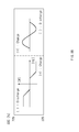
- FIGS. 10A to 10C are graphs of a method for increasing or decreasing the charging/discharging power at a predetermined ratio.
- FIG. 10A illustrates a case in which the SOC value of the battery, which is measured in the SOC measuring unit corresponds to the first operation range a of about 70% to about 100%.
- a correction value by which the charging power is decreased at a predetermined ratio is applied.
- FIG. 10B illustrates a case in which the SOC value of the battery, which is measured in the SOC measuring unit corresponds to the second operation range b of about 30% to about 70%. In this case, it is determined as the normal range to maintain the present state.
- FIG. 10C illustrates a case in which the SOC value of the battery, which is measured in the SOC measuring unit corresponds to the third operation range c of about 0% to about 30%.
- a correction value by which the discharging power is decreased at a predetermined ratio in comparison to the existing discharging power is applied.
- the SOC value of the battery may be maintained within a predetermined range.
- the probability that the SOC value of the battery reaches about 100% or about 0% may be reduced, and the battery may be reduced in capacity when the battery is designed.
Landscapes
- Engineering & Computer Science (AREA)
- Manufacturing & Machinery (AREA)
- General Chemical & Material Sciences (AREA)
- Electrochemistry (AREA)
- Chemical Kinetics & Catalysis (AREA)
- Chemical & Material Sciences (AREA)
- Power Engineering (AREA)
- Mechanical Engineering (AREA)
- Transportation (AREA)
- Life Sciences & Earth Sciences (AREA)
- Sustainable Energy (AREA)
- Sustainable Development (AREA)
- Physics & Mathematics (AREA)
- General Physics & Mathematics (AREA)
- Charge And Discharge Circuits For Batteries Or The Like (AREA)
- Secondary Cells (AREA)
Abstract
Description
Claims (20)
Applications Claiming Priority (5)
| Application Number | Priority Date | Filing Date | Title |
|---|---|---|---|
| KR10-2014-0142610 | 2014-10-21 | ||
| KR10-2014-0142609 | 2014-10-21 | ||
| KR1020140142609A KR101749383B1 (en) | 2014-10-21 | 2014-10-21 | System and method for adjusting the battery soc |
| KR1020140142610A KR20160046550A (en) | 2014-10-21 | 2014-10-21 | System and method for adjusting the battery soc |
| PCT/KR2015/011098 WO2016064171A1 (en) | 2014-10-21 | 2015-10-20 | System and method for correcting soc of battery |
Publications (2)
| Publication Number | Publication Date |
|---|---|
| US20160301234A1 US20160301234A1 (en) | 2016-10-13 |
| US9882409B2 true US9882409B2 (en) | 2018-01-30 |
Family
ID=55761142
Family Applications (1)
| Application Number | Title | Priority Date | Filing Date |
|---|---|---|---|
| US14/917,346 Active 2036-02-03 US9882409B2 (en) | 2014-10-21 | 2015-10-20 | System and method for correcting SOC of battery |
Country Status (6)
| Country | Link |
|---|---|
| US (1) | US9882409B2 (en) |
| EP (1) | EP3051656B1 (en) |
| CN (1) | CN105745811A (en) |
| ES (1) | ES2988721T3 (en) |
| HU (1) | HUE068575T2 (en) |
| WO (1) | WO2016064171A1 (en) |
Cited By (1)
| Publication number | Priority date | Publication date | Assignee | Title |
|---|---|---|---|---|
| US11456610B2 (en) * | 2019-02-20 | 2022-09-27 | Samsung Sdi Co., Ltd. | Internal short sensing battery control apparatus and battery control method |
Families Citing this family (9)
| Publication number | Priority date | Publication date | Assignee | Title |
|---|---|---|---|---|
| CN107627872B (en) * | 2017-08-29 | 2020-01-14 | 广州小鹏汽车科技有限公司 | Battery charging control method and system based on electric vehicle travel mode |
| CN110549900B (en) * | 2018-03-30 | 2021-06-18 | 比亚迪股份有限公司 | Parameter update method and device for electric vehicle and power battery after standing still |
| CN111220919B (en) * | 2018-11-26 | 2021-04-20 | 北汽福田汽车股份有限公司 | Battery electric quantity detection method and device and vehicle |
| KR102685558B1 (en) * | 2019-01-04 | 2024-07-15 | 주식회사 엘지에너지솔루션 | Battery management method, battery device, and vehicle comprising battery device |
| KR102785786B1 (en) | 2019-03-21 | 2025-03-26 | 주식회사 엘지에너지솔루션 | Apparatus and method for controlling battery bank |
| CN110190649B (en) * | 2019-06-01 | 2020-12-29 | 深圳市永航新能源技术有限公司 | A battery capacity evaluation and correction charging and discharging device and correction method |
| CN113049961B (en) * | 2021-02-26 | 2022-07-19 | 佛山职业技术学院 | DZSOC algorithm of lithium iron phosphate battery |
| WO2022198564A1 (en) * | 2021-03-25 | 2022-09-29 | 华为数字能源技术有限公司 | Energy storage system control method and energy storage system |
| CN113848484B (en) * | 2021-09-09 | 2025-03-25 | 华为数字能源技术有限公司 | Energy storage system and parameter calibration method |
Citations (17)
| Publication number | Priority date | Publication date | Assignee | Title |
|---|---|---|---|---|
| US6868318B1 (en) * | 2003-10-14 | 2005-03-15 | General Motors Corporation | Method for adjusting battery power limits in a hybrid electric vehicle to provide consistent launch characteristics |
| EP2055587A2 (en) | 2007-11-04 | 2009-05-06 | GM Global Technology Operations, Inc. | Method for controlling output power of an energy storage device in a powertrain system |
| US20090250277A1 (en) | 2007-01-12 | 2009-10-08 | Grand Kerry E | Battery Equalization Using a Plug-In Charger in a Hybrid Electric Vehicle |
| EP2145808A1 (en) | 2007-05-15 | 2010-01-20 | Toyota Jidosha Kabushiki Kaisha | Vehicle and its control method |
| US20110115439A1 (en) | 2009-11-17 | 2011-05-19 | Hyundai Motor Company | Battery's state-of-charge balancing control method for hybrid vehicle |
| US20110273129A1 (en) * | 2010-05-04 | 2011-11-10 | Xtreme Power Inc. | Managing Renewable Power Generation |
| US20120161707A1 (en) | 2010-12-28 | 2012-06-28 | Samsung Sdi Co., Ltd | Balancing method and balancing system of battery pack |
| US20130113433A1 (en) * | 2010-07-13 | 2013-05-09 | Honda Motor Co., Ltd. | Storage capacity management system |
| DE102012208464B3 (en) | 2012-05-21 | 2013-07-04 | Deere & Company | Conditioning device for self-propelled forage harvester, for harvesting plants or parts of plants, has crop residues removing element whose surface is adjacent to roller and arcuately-extended around part of circumference of roller |
| KR101337576B1 (en) | 2012-06-14 | 2013-12-06 | 이엔테크놀로지 주식회사 | Method and system for state of charge management |
| KR20140073627A (en) | 2012-11-30 | 2014-06-17 | 주식회사 포스코아이씨티 | Apparatus and Method for Managing Battery |
| JP2014112980A (en) | 2011-03-25 | 2014-06-19 | Sanyo Electric Co Ltd | Battery module, battery system, power-supply device, and mobile body |
| US20140292080A1 (en) | 2011-11-10 | 2014-10-02 | Evonik Industries Ag | Method for providing control power using an energy store having variable deadband width when providing the control power |
| US20150015213A1 (en) * | 2012-03-28 | 2015-01-15 | Aerovironment, Inc. | Frequency responsive charging system and method |
| US20150142236A1 (en) | 2012-05-21 | 2015-05-21 | Robert Bosch Gmbh | Method and device for controlling an internal combustion engine |
| US20160079778A1 (en) * | 2013-04-29 | 2016-03-17 | Welsengen Limited | Apparatus and method for managing stored energy |
| US20160254683A1 (en) * | 2013-10-16 | 2016-09-01 | Toyota Jidosha Kabushiki Kaisha | Electric storage system |
Family Cites Families (1)
| Publication number | Priority date | Publication date | Assignee | Title |
|---|---|---|---|---|
| DE102013206808A1 (en) * | 2013-04-16 | 2014-10-16 | Younicos Ag | Method and device for controlling the state of charge of a battery power plant |
-
2015
- 2015-10-20 US US14/917,346 patent/US9882409B2/en active Active
- 2015-10-20 HU HUE15837076A patent/HUE068575T2/en unknown
- 2015-10-20 WO PCT/KR2015/011098 patent/WO2016064171A1/en not_active Ceased
- 2015-10-20 CN CN201580001968.9A patent/CN105745811A/en active Pending
- 2015-10-20 EP EP15837076.7A patent/EP3051656B1/en active Active
- 2015-10-20 ES ES15837076T patent/ES2988721T3/en active Active
Patent Citations (20)
| Publication number | Priority date | Publication date | Assignee | Title |
|---|---|---|---|---|
| US6868318B1 (en) * | 2003-10-14 | 2005-03-15 | General Motors Corporation | Method for adjusting battery power limits in a hybrid electric vehicle to provide consistent launch characteristics |
| US20090250277A1 (en) | 2007-01-12 | 2009-10-08 | Grand Kerry E | Battery Equalization Using a Plug-In Charger in a Hybrid Electric Vehicle |
| EP2145808A1 (en) | 2007-05-15 | 2010-01-20 | Toyota Jidosha Kabushiki Kaisha | Vehicle and its control method |
| US20100152938A1 (en) | 2007-05-15 | 2010-06-17 | Takanori Aoki | Vehicle and control method of vehicle |
| EP2055587A2 (en) | 2007-11-04 | 2009-05-06 | GM Global Technology Operations, Inc. | Method for controlling output power of an energy storage device in a powertrain system |
| US20090118962A1 (en) | 2007-11-04 | 2009-05-07 | Gm Global Technology Operations, Inc. | Method for controlling output power of an energy storage device in a powertrain system |
| US20110115439A1 (en) | 2009-11-17 | 2011-05-19 | Hyundai Motor Company | Battery's state-of-charge balancing control method for hybrid vehicle |
| KR20110054135A (en) | 2009-11-17 | 2011-05-25 | 현대자동차주식회사 | Soc band strategy for hev |
| US20110273129A1 (en) * | 2010-05-04 | 2011-11-10 | Xtreme Power Inc. | Managing Renewable Power Generation |
| US20130113433A1 (en) * | 2010-07-13 | 2013-05-09 | Honda Motor Co., Ltd. | Storage capacity management system |
| US20120161707A1 (en) | 2010-12-28 | 2012-06-28 | Samsung Sdi Co., Ltd | Balancing method and balancing system of battery pack |
| JP2014112980A (en) | 2011-03-25 | 2014-06-19 | Sanyo Electric Co Ltd | Battery module, battery system, power-supply device, and mobile body |
| US20140292080A1 (en) | 2011-11-10 | 2014-10-02 | Evonik Industries Ag | Method for providing control power using an energy store having variable deadband width when providing the control power |
| US20150015213A1 (en) * | 2012-03-28 | 2015-01-15 | Aerovironment, Inc. | Frequency responsive charging system and method |
| DE102012208464B3 (en) | 2012-05-21 | 2013-07-04 | Deere & Company | Conditioning device for self-propelled forage harvester, for harvesting plants or parts of plants, has crop residues removing element whose surface is adjacent to roller and arcuately-extended around part of circumference of roller |
| US20150142236A1 (en) | 2012-05-21 | 2015-05-21 | Robert Bosch Gmbh | Method and device for controlling an internal combustion engine |
| KR101337576B1 (en) | 2012-06-14 | 2013-12-06 | 이엔테크놀로지 주식회사 | Method and system for state of charge management |
| KR20140073627A (en) | 2012-11-30 | 2014-06-17 | 주식회사 포스코아이씨티 | Apparatus and Method for Managing Battery |
| US20160079778A1 (en) * | 2013-04-29 | 2016-03-17 | Welsengen Limited | Apparatus and method for managing stored energy |
| US20160254683A1 (en) * | 2013-10-16 | 2016-09-01 | Toyota Jidosha Kabushiki Kaisha | Electric storage system |
Non-Patent Citations (2)
| Title |
|---|
| Extended European Search Report for Appl. No. 15837076.7 dated Dec. 21, 2016. |
| Liu, H. et al, "Decentralized Vehicle-to-Grid Control for Primary Frequency Regulation Considering Charging Demands," IEEE Transactions on Power Systems, Aug. 2013, vol. 28, No. 3, pp. 3480-3489. |
Cited By (1)
| Publication number | Priority date | Publication date | Assignee | Title |
|---|---|---|---|---|
| US11456610B2 (en) * | 2019-02-20 | 2022-09-27 | Samsung Sdi Co., Ltd. | Internal short sensing battery control apparatus and battery control method |
Also Published As
| Publication number | Publication date |
|---|---|
| WO2016064171A1 (en) | 2016-04-28 |
| EP3051656B1 (en) | 2024-09-11 |
| US20160301234A1 (en) | 2016-10-13 |
| EP3051656A1 (en) | 2016-08-03 |
| HUE068575T2 (en) | 2025-01-28 |
| ES2988721T3 (en) | 2024-11-21 |
| CN105745811A (en) | 2016-07-06 |
| EP3051656A4 (en) | 2017-01-18 |
Similar Documents
| Publication | Publication Date | Title |
|---|---|---|
| US9882409B2 (en) | System and method for correcting SOC of battery | |
| US9142980B2 (en) | Apparatus and method for controlling charge capacity balancing operation of secondary battery cell | |
| US9475398B2 (en) | Optimization-based predictive method for battery charging | |
| US9166257B2 (en) | Method for charging and method for determining an end-of-charge criterion of a nickel-based battery | |
| US10211651B2 (en) | Device and method for managing SOC and SOH of parallel-connected battery pack | |
| KR101500547B1 (en) | Apparatus and method for balancing of battery cell's charging capacity | |
| US20170104350A1 (en) | Device and method for controlling a plurality of cells of a battery | |
| KR20150054464A (en) | Charging method of battery and battery charging system | |
| US20140132202A1 (en) | Method and apparatus for controlling charging of secondary battery | |
| KR20210056301A (en) | Apparatus and method for processing voltage data of battery cell | |
| US20150042351A1 (en) | Method and System for Characterizing Battery Cells for Use in Battery Packs | |
| KR101614046B1 (en) | Apparatus for managing battery system | |
| KR20110117992A (en) | Battery charging system and its charging method | |
| KR102020044B1 (en) | Battery charging system, and method for controlling maximum capacity charging in battery module using the same | |
| KR20190078092A (en) | Apparatus for managing battery | |
| KR101491460B1 (en) | Active cell balancing method of battery and system thereof | |
| KR102895821B1 (en) | Battery managing apparatus and method thereof | |
| KR102895834B1 (en) | Battery managing apparatus and method thereof | |
| US9466990B2 (en) | Method for enhancing a battery management system, battery management system, battery system and motor vehicle | |
| KR101749383B1 (en) | System and method for adjusting the battery soc | |
| CN120936892A (en) | Battery management device and method thereof | |
| CN121127755A (en) | Battery management device and method thereof | |
| KR101915183B1 (en) | Apparatus and method for setting and operating reference SOC of active cell balancing using common bus | |
| KR102911276B1 (en) | Data management apparatus for energy storage apparatus and apparatus for predicting life | |
| KR20100077141A (en) | Battery charging system |
Legal Events
| Date | Code | Title | Description |
|---|---|---|---|
| AS | Assignment |
Owner name: LG CHEM, LTD., KOREA, REPUBLIC OF Free format text: ASSIGNMENT OF ASSIGNORS INTEREST;ASSIGNORS:PARK, JEONG SEOK;YOON, SUNG YUL;CHO, TAE SHIN;AND OTHERS;REEL/FRAME:037924/0156 Effective date: 20160223 |
|
| STCF | Information on status: patent grant |
Free format text: PATENTED CASE |
|
| MAFP | Maintenance fee payment |
Free format text: PAYMENT OF MAINTENANCE FEE, 4TH YEAR, LARGE ENTITY (ORIGINAL EVENT CODE: M1551); ENTITY STATUS OF PATENT OWNER: LARGE ENTITY Year of fee payment: 4 |
|
| AS | Assignment |
Owner name: LG ENERGY SOLUTION, LTD., KOREA, REPUBLIC OF Free format text: ASSIGNMENT OF ASSIGNORS INTEREST;ASSIGNOR:LG CHEM, LTD.;REEL/FRAME:058295/0068 Effective date: 20211027 Owner name: LG ENERGY SOLUTION, LTD., KOREA, REPUBLIC OF Free format text: ASSIGNMENT OF ASSIGNOR'S INTEREST;ASSIGNOR:LG CHEM, LTD.;REEL/FRAME:058295/0068 Effective date: 20211027 |
|
| MAFP | Maintenance fee payment |
Free format text: PAYMENT OF MAINTENANCE FEE, 8TH YEAR, LARGE ENTITY (ORIGINAL EVENT CODE: M1552); ENTITY STATUS OF PATENT OWNER: LARGE ENTITY Year of fee payment: 8 |