US9879814B1 - Pigging support system - Google Patents

Pigging support system Download PDF

Info

Publication number
US9879814B1
US9879814B1 US14/801,035 US201514801035A US9879814B1 US 9879814 B1 US9879814 B1 US 9879814B1 US 201514801035 A US201514801035 A US 201514801035A US 9879814 B1 US9879814 B1 US 9879814B1
Authority
US
United States
Prior art keywords
pig
ring
pipe
pipeline
support
Prior art date
Legal status (The legal status is an assumption and is not a legal conclusion. Google has not performed a legal analysis and makes no representation as to the accuracy of the status listed.)
Active, expires
Application number
US14/801,035
Inventor
Richard Brent Mackey
Current Assignee (The listed assignees may be inaccurate. Google has not performed a legal analysis and makes no representation or warranty as to the accuracy of the list.)
Individual
Original Assignee
Individual
Priority date (The priority date is an assumption and is not a legal conclusion. Google has not performed a legal analysis and makes no representation as to the accuracy of the date listed.)
Filing date
Publication date
Application filed by Individual filed Critical Individual
Priority to US14/801,035 priority Critical patent/US9879814B1/en
Application granted granted Critical
Publication of US9879814B1 publication Critical patent/US9879814B1/en
Active legal-status Critical Current
Adjusted expiration legal-status Critical

Links

Images

Classifications

    • FMECHANICAL ENGINEERING; LIGHTING; HEATING; WEAPONS; BLASTING
    • F16ENGINEERING ELEMENTS AND UNITS; GENERAL MEASURES FOR PRODUCING AND MAINTAINING EFFECTIVE FUNCTIONING OF MACHINES OR INSTALLATIONS; THERMAL INSULATION IN GENERAL
    • F16LPIPES; JOINTS OR FITTINGS FOR PIPES; SUPPORTS FOR PIPES, CABLES OR PROTECTIVE TUBING; MEANS FOR THERMAL INSULATION IN GENERAL
    • F16L55/00Devices or appurtenances for use in, or in connection with, pipes or pipe systems
    • F16L55/26Pigs or moles, i.e. devices movable in a pipe or conduit with or without self-contained propulsion means
    • F16L55/46Launching or retrieval of pigs or moles
    • BPERFORMING OPERATIONS; TRANSPORTING
    • B08CLEANING
    • B08BCLEANING IN GENERAL; PREVENTION OF FOULING IN GENERAL
    • B08B9/00Cleaning hollow articles by methods or apparatus specially adapted thereto
    • B08B9/02Cleaning pipes or tubes or systems of pipes or tubes
    • B08B9/027Cleaning the internal surfaces; Removal of blockages
    • B08B9/04Cleaning the internal surfaces; Removal of blockages using cleaning devices introduced into and moved along the pipes
    • B08B9/053Cleaning the internal surfaces; Removal of blockages using cleaning devices introduced into and moved along the pipes moved along the pipes by a fluid, e.g. by fluid pressure or by suction
    • B08B9/055Cleaning the internal surfaces; Removal of blockages using cleaning devices introduced into and moved along the pipes moved along the pipes by a fluid, e.g. by fluid pressure or by suction the cleaning devices conforming to, or being conformable to, substantially the same cross-section of the pipes, e.g. pigs or moles
    • FMECHANICAL ENGINEERING; LIGHTING; HEATING; WEAPONS; BLASTING
    • F16ENGINEERING ELEMENTS AND UNITS; GENERAL MEASURES FOR PRODUCING AND MAINTAINING EFFECTIVE FUNCTIONING OF MACHINES OR INSTALLATIONS; THERMAL INSULATION IN GENERAL
    • F16LPIPES; JOINTS OR FITTINGS FOR PIPES; SUPPORTS FOR PIPES, CABLES OR PROTECTIVE TUBING; MEANS FOR THERMAL INSULATION IN GENERAL
    • F16L55/00Devices or appurtenances for use in, or in connection with, pipes or pipe systems
    • F16L55/07Arrangement or mounting of devices, e.g. valves, for venting or aerating or draining
    • FMECHANICAL ENGINEERING; LIGHTING; HEATING; WEAPONS; BLASTING
    • F16ENGINEERING ELEMENTS AND UNITS; GENERAL MEASURES FOR PRODUCING AND MAINTAINING EFFECTIVE FUNCTIONING OF MACHINES OR INSTALLATIONS; THERMAL INSULATION IN GENERAL
    • F16LPIPES; JOINTS OR FITTINGS FOR PIPES; SUPPORTS FOR PIPES, CABLES OR PROTECTIVE TUBING; MEANS FOR THERMAL INSULATION IN GENERAL
    • F16L41/00Branching pipes; Joining pipes to walls
    • F16L41/02Branch units, e.g. made in one piece, welded, riveted
    • F16L41/021T- or cross-pieces
    • FMECHANICAL ENGINEERING; LIGHTING; HEATING; WEAPONS; BLASTING
    • F16ENGINEERING ELEMENTS AND UNITS; GENERAL MEASURES FOR PRODUCING AND MAINTAINING EFFECTIVE FUNCTIONING OF MACHINES OR INSTALLATIONS; THERMAL INSULATION IN GENERAL
    • F16LPIPES; JOINTS OR FITTINGS FOR PIPES; SUPPORTS FOR PIPES, CABLES OR PROTECTIVE TUBING; MEANS FOR THERMAL INSULATION IN GENERAL
    • F16L41/00Branching pipes; Joining pipes to walls
    • F16L41/08Joining pipes to walls or pipes, the joined pipe axis being perpendicular to the plane of a wall or to the axis of another pipe
    • FMECHANICAL ENGINEERING; LIGHTING; HEATING; WEAPONS; BLASTING
    • F16ENGINEERING ELEMENTS AND UNITS; GENERAL MEASURES FOR PRODUCING AND MAINTAINING EFFECTIVE FUNCTIONING OF MACHINES OR INSTALLATIONS; THERMAL INSULATION IN GENERAL
    • F16LPIPES; JOINTS OR FITTINGS FOR PIPES; SUPPORTS FOR PIPES, CABLES OR PROTECTIVE TUBING; MEANS FOR THERMAL INSULATION IN GENERAL
    • F16L55/00Devices or appurtenances for use in, or in connection with, pipes or pipe systems
    • F16L55/26Pigs or moles, i.e. devices movable in a pipe or conduit with or without self-contained propulsion means

Definitions

  • the present invention relates generally to oil and gas pipelines, and more specifically, to a pig support system.
  • Pigging in the context of pipelines refers to the practice of using devices known as “pigs” to perform various maintenance operations on a pipeline. This is done without stopping the flow of the product in the pipeline. These operations include but are not limited to cleaning and inspecting the pipeline. This is accomplished by inserting the pig into a “pig launcher” or “launching station”.
  • the pig launching station consists of an oversized section in the pipeline which reduces to the normal diameter. The launching station is then closed and the pressure-driven flow of the product in the pipeline is used to push it down the pipe until it reaches the receiving trap, e.g. pig catcher or receiving station.
  • FIG. 1 depicts a cross sectional view of a conventional pig support system.
  • system 101 includes one or more support bars 103 which are welded to the pipe inlet/outlet orifice 105 .
  • a common disadvantage with the conventional pig support system 101 is the exposed pig support bar edges which can tear the elastomeric seals 107 on the pig.
  • Another common disadvantage is the offset distance between the horizontal support bars and the inner diameter of the pipeline. The offset distance is present due to the conventional manufacturing process which creates a means for the pig to get stuck on the open orifice surface.
  • a final disadvantage of conventional pig support systems is the labor intensive manufacturing process. Conventional pig support fabrication is a time consuming, multiple step process.
  • FIG. 1 is a front, cross-sectional view of conventional a pig support system
  • FIG. 2 is an oblique view of the preferred embodiment of the present application.
  • FIG. 3 is an oblique, cross sectional view of the preferred embodiment of the present application.
  • FIG. 4 is an oblique view of pig support system in accordance with an alternate embodiment of the present application.
  • FIG. 5 is an oblique, section view of pig support system in accordance with an alternate embodiment of the present application.
  • FIGS. 6A, 6B , & 6 C are oblique views of the pig support system in accordance with an alternate embodiment of the present application.
  • FIG. 7 is an oblique view of an alternate embodiment of the present application.
  • FIGS. 8A, 8B , & 8 C are oblique views of the pig support system in accordance with an alternate embodiment of the present application.
  • the system and method of use in accordance with the present application overcomes one or more of the above-discussed problems commonly associated with pig support systems.
  • the system of the present application includes pre-manufactured pig support which is free of sharp edges which can cause damage to the pig.
  • the exemplary system is configured to eliminate drastic offset surfaces which can cause the pig to get stuck.
  • the manufacturing of the “pig support ring” dramatically increases the ease of installation and greatly reduces the installation labor time.
  • FIG. 2 depicts an oblique view of a pig support system 201 in accordance with the preferred embodiment of the present application. It will be appreciated that system 201 overcomes at least one of the above-listed problems commonly associated with the conventional pig support systems.
  • system 201 preferably includes a ring 205 and one or more pig support bars 203 .
  • Ring 205 's diameter surface 207 is sized to fit into a specific pipeline inner diameter. Therefore, system 201 is configurable based on the inner diameter of the pipeline.
  • the pig support bars 203 are attached to ring 205 by means of welding.
  • the pig support bars 203 provide the support surface for the pig as it travels over the open orifice.
  • One of the unique features believed characteristic of the present application is the added capability to pre-manufacture system 201 prior to the pipeline manufacturing
  • Another unique feature is the manufacturing quality improvement that can be added when fabricating system 201 on a precision, standalone fixture.
  • the pig support bars 203 are flush with the upper surface of ring 205 which will allow the pig to travel smoothly over the support system. This feature overcomes common disadvantages with conventional pig support systems, e.g. protruding pig support bars tearing the elastomeric seals on the pig.
  • FIG. 3 a sectional, oblique view is given which shows system 201 configured in a pipeline tee 301 .
  • the pig supporting surface 303 of system 201 is recessed slightly below the inner diameter surface 305 of pipeline tee 301 to prevent protruding edges which could cause the pig to get stuck or damaged.
  • System 201 attaches to the pipeline tee by means of welding.
  • FIG. 4 depicts an oblique view of a pig support system 401 in accordance with an alternate embodiment of the present application.
  • System 401 is substantially similar in function to the System 201 discussed herein and hereby incorporates one or more of the features discussed herein, and vice-versa.
  • System 401 includes a ring 405 which is configurable in diameter 407 to fit in the pipeline inner diameter. Similarly, system 401 is scalable and configurable based on the pipeline size. In this embodiment, one or more pig support bars 403 are permanently attached to ring 401 . The pig support bars 403 are flush with the upper surface of ring 405 which will allow the pig to travel smoothly over the support system.
  • One or more pig support flanges 409 are uniquely included in system 401 .
  • the pig support flanges 409 provide further support of the pig as it travels over the open orifice.
  • the flanges are permanently attached to the ring 405 and are located flush with the upper surface of the ring. Similarly, this feature allows the pig to travel smoothly over the support system while preventing damage or sticking.
  • FIG. 5 a sectional, oblique view is given which shows system 401 configured in a pipeline tee 501 .
  • the pig supporting surface 503 of system 401 is recessed slightly below the inner diameter surface 505 of pipeline tee 501 to prevent protruding edges which could cause the pig to get stuck or damaged.
  • System 201 attaches to the pipeline tee by means of welding. It is appreciated that the pig support surface 503 provides extended support due to the flange configuration as previously mentioned.
  • FIGS. 6A . 6 B, and 6 C depicts oblique views of an alternate embodiment, namely, lateral pipeline pig support system 601 , of the present application.
  • FIG. 6A shows how pig support system 603 attaches to a lateral pipeline 605 .
  • Pig support system 803 is substantially similar in function to the System 201 & 401 discussed herein and hereby incorporates one or more of the features discussed herein, and vice-versa.
  • One end of lateral pipeline 605 is contoured to fit on the outer diameter of the main pipeline 609 .
  • Pig support system 603 is permanently attached to the lateral pipeline 605 by means of welding prior as shown in FIG. 6A .
  • the lateral pipeline 605 (with pig support system 603 previously attached) is attached to the main pipeline 609 by means of welding.
  • Conventional pig support systems for lateral pipelines use uniquely fabricated pigging support bars.
  • the fabrication process for conventional pig support systems for lateral pipelines includes layout, cutting, grinding, fitting, and welding which is labor intensive and error prone. This is viewed as a common disadvantage of conventional pig support systems for lateral pipelines.
  • FIG. 6C shows an oblique view of the final assembly of system 601 lateral pipeline pig support system.
  • System 601 eliminates the labor intensive and error prone process of custom fabricating pigging support bars for lateral pipelines
  • System 601 achieves this by using pre-manufactured pig support systems 603 which are configured to fit in the respective lateral pipe inner diameter. This is viewed as a sizeable advantage of this alternate embodiment of the present application.
  • FIG. 7 depicts an oblique view of a pig support system 701 in accordance with an alternate embodiment of the present application.
  • System 701 is substantially similar in function to the System 201 & 401 discussed herein and hereby incorporates one or more of the features discussed herein, and vice-versa.
  • System 701 includes a saddle ring 703 which is contoured to fit on an outer diameter of a pipeline.
  • the “saddle” portion of saddle ring 703 acts as a stiffener when welded to the outer diameter of a primary pipeline.
  • one or more pig support bars are permanently attached to saddle ring 703 .
  • the pig support bars protrude through the saddle such that they are flush with the inner diameter of the primary pipeline when system 701 is installed.
  • system 701 is scalable and configurable based on the pipeline size.
  • FIGS. 8A, 8B, and 8C depicts oblique views of an alternate embodiment, namely, lateral pipeline pig support system 801 , of the present application.
  • FIG. 8A shows how pig support system 701 attaches to a primary pipeline 803 .
  • System 701 attaches permanently to the outer diameter of primary pipeline 803 by means of welding.
  • the lateral pipeline 805 is located in the pig support system 701 .
  • the outer diameter of the lateral pipeline 805 fits in the inner diameter of the pig support system 701 and is permanently attached by welding.
  • the pig support bars located in system 701 are flush with the inner diameter of the primary pipeline 803 and provide a support surface for the pig when passing over the lateral orifice.
  • FIG. 8C depicts an oblique view of the final assembly of system 801 lateral pipeline pig support system.
  • System 801 eliminates the labor intensive and error prone process of custom fabricating pigging support bars for lateral pipelines.
  • System 801 achieves this by using pre-manufactured pig support systems 701 which are configured to fit the respective lateral pipe. This is viewed as a sizeable advantage of this alternate embodiment of the present application.

Landscapes

  • Engineering & Computer Science (AREA)
  • General Engineering & Computer Science (AREA)
  • Mechanical Engineering (AREA)
  • Physics & Mathematics (AREA)
  • Fluid Mechanics (AREA)
  • Chemical & Material Sciences (AREA)
  • Combustion & Propulsion (AREA)
  • Cleaning In General (AREA)

Abstract

A pig support system for a pipe includes a saddle having a flange integral with a ring extending therefrom, the ring forming an opening configured to provide passage to an inner channel formed by the pipe; a plurality of ribs disposed within the ring, the plurality of ribs having longitudinal lengths and configured to extend along the inner surface of the pipe; and, a lateral pipe configured to engage with the ring, the lateral pipe creating a second passage in fluid communication with the opening of the ring, the lateral pipe being configured to extend relatively perpendicular to the pipe.

Description

BACKGROUND 1. Field of the Invention
The present invention relates generally to oil and gas pipelines, and more specifically, to a pig support system.
2. Description of Related Art
Pigging in the context of pipelines refers to the practice of using devices known as “pigs” to perform various maintenance operations on a pipeline. This is done without stopping the flow of the product in the pipeline. These operations include but are not limited to cleaning and inspecting the pipeline. This is accomplished by inserting the pig into a “pig launcher” or “launching station”. The pig launching station consists of an oversized section in the pipeline which reduces to the normal diameter. The launching station is then closed and the pressure-driven flow of the product in the pipeline is used to push it down the pipe until it reaches the receiving trap, e.g. pig catcher or receiving station.
Pigs can get stuck in the pipeline when traveling past two large unsupported orifices. Pig support systems are known in the art and provide a means of supporting the pig as it passes over the orifice. In prior art, horizontal bars which run parallel to the pipeline axis are welded in the lateral inlet and outlets orifices. For example, FIG. 1 depicts a cross sectional view of a conventional pig support system. In the exemplary embodiment, system 101 includes one or more support bars 103 which are welded to the pipe inlet/outlet orifice 105.
A common disadvantage with the conventional pig support system 101 is the exposed pig support bar edges which can tear the elastomeric seals 107 on the pig. Another common disadvantage is the offset distance between the horizontal support bars and the inner diameter of the pipeline. The offset distance is present due to the conventional manufacturing process which creates a means for the pig to get stuck on the open orifice surface. A final disadvantage of conventional pig support systems is the labor intensive manufacturing process. Conventional pig support fabrication is a time consuming, multiple step process.
Although great strides have been made in the area of pig support systems, many shortcomings remain.
DESCRIPTION OF THE DRAWINGS
The novel features believed characteristic of the embodiments of the present application are set forth in the appended claims. However, the embodiments themselves, as well as a preferred mode of use, and further objectives and advantages thereof, will best be understood by reference to the following detailed description when read in conjunction with the accompanying drawings, wherein:
FIG. 1 is a front, cross-sectional view of conventional a pig support system;
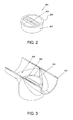
FIG. 2 is an oblique view of the preferred embodiment of the present application;
FIG. 3 is an oblique, cross sectional view of the preferred embodiment of the present application;
FIG. 4 is an oblique view of pig support system in accordance with an alternate embodiment of the present application;
FIG. 5 is an oblique, section view of pig support system in accordance with an alternate embodiment of the present application;
FIGS. 6A, 6B, & 6C are oblique views of the pig support system in accordance with an alternate embodiment of the present application;
FIG. 7 is an oblique view of an alternate embodiment of the present application; and
FIGS. 8A, 8B, & 8C are oblique views of the pig support system in accordance with an alternate embodiment of the present application.
While the system and method of use of the present application is susceptible to various modifications and alternative forms, specific embodiments thereof have been shown by way of example in the drawings and are herein described in detail. It should be understood, however, that the description herein of specific embodiments is not intended to limit the invention to the particular embodiment disclosed, but on the contrary, the intention is to cover all modifications, equivalents, and alternatives falling within the spirit and scope of the present application as defined by the appended claims.
DETAILED DESCRIPTION OF THE PREFERRED EMBODIMENT
Illustrative embodiments of the system and method of use of the present application are provided below. It will of course be appreciated that in the development of any actual embodiment, numerous implementation-specific decisions will be made to achieve the developer's specific goals, such as compliance with system-related and business-related constraints, which will vary from one implementation to another. Moreover, it will be appreciated that such a development effort might be complex and time-consuming, but would nevertheless be a routine undertaking for those of ordinary skill in the art having the benefit of this disclosure.
The system and method of use in accordance with the present application overcomes one or more of the above-discussed problems commonly associated with pig support systems. Specifically, the system of the present application includes pre-manufactured pig support which is free of sharp edges which can cause damage to the pig. Additionally, the exemplary system is configured to eliminate drastic offset surfaces which can cause the pig to get stuck. The manufacturing of the “pig support ring” dramatically increases the ease of installation and greatly reduces the installation labor time. These and other unique features of the pig support system and methods of use are discussed below and illustrated in the accompanying drawings.
The system and method of use will be understood, both as to its structure and operation, from the accompanying drawings, taken in conjunction with the accompanying description. Several embodiments of the pig support system are presented herein. It should be understood that various components, parts, and features of the different embodiments may be combined together and/or interchanged with one another, all of which are within the scope of the present application, even though not all variations and particular embodiments are shown in the drawings. It should also be understood that the mixing and matching of features, elements, and/or functions between various embodiments is expressly contemplated herein so that one of ordinary skill in the art would appreciate from this disclosure that the features, elements, and/or functions of one embodiment may be incorporated into another embodiment as appropriate, unless described otherwise.
Referring now to the drawings wherein like reference characters identify corresponding or similar elements throughout the several views, FIG. 2 depicts an oblique view of a pig support system 201 in accordance with the preferred embodiment of the present application. It will be appreciated that system 201 overcomes at least one of the above-listed problems commonly associated with the conventional pig support systems.
In the contemplated embodiment, system 201 preferably includes a ring 205 and one or more pig support bars 203. Ring 205 's diameter surface 207 is sized to fit into a specific pipeline inner diameter. Therefore, system 201 is configurable based on the inner diameter of the pipeline. The pig support bars 203 are attached to ring 205 by means of welding. The pig support bars 203 provide the support surface for the pig as it travels over the open orifice. One of the unique features believed characteristic of the present application is the added capability to pre-manufacture system 201 prior to the pipeline manufacturing Another unique feature is the manufacturing quality improvement that can be added when fabricating system 201 on a precision, standalone fixture.
As will be explained more fully below, the pig support bars 203 are flush with the upper surface of ring 205 which will allow the pig to travel smoothly over the support system. This feature overcomes common disadvantages with conventional pig support systems, e.g. protruding pig support bars tearing the elastomeric seals on the pig.
In FIG. 3, a sectional, oblique view is given which shows system 201 configured in a pipeline tee 301. The pig supporting surface 303 of system 201 is recessed slightly below the inner diameter surface 305 of pipeline tee 301 to prevent protruding edges which could cause the pig to get stuck or damaged. System 201 attaches to the pipeline tee by means of welding.
FIG. 4 depicts an oblique view of a pig support system 401 in accordance with an alternate embodiment of the present application. System 401 is substantially similar in function to the System 201 discussed herein and hereby incorporates one or more of the features discussed herein, and vice-versa.
System 401 includes a ring 405 which is configurable in diameter 407 to fit in the pipeline inner diameter. Similarly, system 401 is scalable and configurable based on the pipeline size. In this embodiment, one or more pig support bars 403 are permanently attached to ring 401. The pig support bars 403 are flush with the upper surface of ring 405 which will allow the pig to travel smoothly over the support system.
One or more pig support flanges 409 are uniquely included in system 401. The pig support flanges 409 provide further support of the pig as it travels over the open orifice. The flanges are permanently attached to the ring 405 and are located flush with the upper surface of the ring. Similarly, this feature allows the pig to travel smoothly over the support system while preventing damage or sticking.
In FIG. 5, a sectional, oblique view is given which shows system 401 configured in a pipeline tee 501. The pig supporting surface 503 of system 401 is recessed slightly below the inner diameter surface 505 of pipeline tee 501 to prevent protruding edges which could cause the pig to get stuck or damaged. System 201 attaches to the pipeline tee by means of welding. It is appreciated that the pig support surface 503 provides extended support due to the flange configuration as previously mentioned.
FIGS. 6A. 6B, and 6C depicts oblique views of an alternate embodiment, namely, lateral pipeline pig support system 601, of the present application.
FIG. 6A shows how pig support system 603 attaches to a lateral pipeline 605. Pig support system 803 is substantially similar in function to the System 201 & 401 discussed herein and hereby incorporates one or more of the features discussed herein, and vice-versa. One end of lateral pipeline 605 is contoured to fit on the outer diameter of the main pipeline 609. Pig support system 603 is permanently attached to the lateral pipeline 605 by means of welding prior as shown in FIG. 6A.
In FIG. 6B, the lateral pipeline 605 (with pig support system 603 previously attached) is attached to the main pipeline 609 by means of welding. Conventional pig support systems for lateral pipelines use uniquely fabricated pigging support bars. The fabrication process for conventional pig support systems for lateral pipelines includes layout, cutting, grinding, fitting, and welding which is labor intensive and error prone. This is viewed as a common disadvantage of conventional pig support systems for lateral pipelines.
In this alternate embodiment, FIG. 6C shows an oblique view of the final assembly of system 601 lateral pipeline pig support system. System 601 eliminates the labor intensive and error prone process of custom fabricating pigging support bars for lateral pipelines System 601 achieves this by using pre-manufactured pig support systems 603 which are configured to fit in the respective lateral pipe inner diameter. This is viewed as a sizeable advantage of this alternate embodiment of the present application.
FIG. 7 depicts an oblique view of a pig support system 701 in accordance with an alternate embodiment of the present application. System 701 is substantially similar in function to the System 201 & 401 discussed herein and hereby incorporates one or more of the features discussed herein, and vice-versa.
System 701 includes a saddle ring 703 which is contoured to fit on an outer diameter of a pipeline. The “saddle” portion of saddle ring 703 acts as a stiffener when welded to the outer diameter of a primary pipeline. In this embodiment, one or more pig support bars are permanently attached to saddle ring 703. The pig support bars protrude through the saddle such that they are flush with the inner diameter of the primary pipeline when system 701 is installed. Similarly, system 701 is scalable and configurable based on the pipeline size.
FIGS. 8A, 8B, and 8C depicts oblique views of an alternate embodiment, namely, lateral pipeline pig support system 801, of the present application.
FIG. 8A shows how pig support system 701 attaches to a primary pipeline 803. System 701 attaches permanently to the outer diameter of primary pipeline 803 by means of welding. Secondly, in FIG. 8B the lateral pipeline 805 is located in the pig support system 701. The outer diameter of the lateral pipeline 805 fits in the inner diameter of the pig support system 701 and is permanently attached by welding. The pig support bars located in system 701 are flush with the inner diameter of the primary pipeline 803 and provide a support surface for the pig when passing over the lateral orifice.
In this alternate embodiment, FIG. 8C depicts an oblique view of the final assembly of system 801 lateral pipeline pig support system. System 801 eliminates the labor intensive and error prone process of custom fabricating pigging support bars for lateral pipelines. System 801 achieves this by using pre-manufactured pig support systems 701 which are configured to fit the respective lateral pipe. This is viewed as a sizeable advantage of this alternate embodiment of the present application.
The particular embodiments disclosed above are illustrative only, as the embodiments may be modified and practiced in different but equivalent manners apparent to those skilled in the art having the benefit of the teachings herein. It is therefore evident that the particular embodiments disclosed above may be altered or modified, and all such variations are considered within the scope and spirit of the application. Accordingly, the protection sought herein is as set forth in the description. Although the present embodiments are shown above, they are not limited to just these embodiments, but are amenable to various changes and modifications without departing from the spirit thereof.

Claims (1)

What is claimed is:
1. A pig support system for a pipe, comprising:
a saddle having:
a flange integral with a ring extending therefrom, the ring forming an opening configured to provide passage to an inner channel formed by the pipe;
wherein the flange is contoured to match an outer surface of the pipe and provides support for the ring;
a plurality of ribs disposed within the ring, the plurality of ribs having longitudinal lengths and configured to extend from a first side of the ring to a second side of the ring and across the opening; and
a lateral pipe configured to engage with the ring, the lateral pipe creating a second passage in fluid communication with the opening of the ring, the lateral pipe being configured to extend relatively perpendicular to the pipe;
wherein the ribs have a top surface flush with a top surface of the ring and a top surface of the flange, thereby providing a continuous smooth surface on which to support the pig; and
wherein the ribs provide fluid passage to the second passage.
US14/801,035 2014-07-16 2015-07-16 Pigging support system Active 2036-03-07 US9879814B1 (en)

Priority Applications (1)

Application Number Priority Date Filing Date Title
US14/801,035 US9879814B1 (en) 2014-07-16 2015-07-16 Pigging support system

Applications Claiming Priority (2)

Application Number Priority Date Filing Date Title
US201462025082P 2014-07-16 2014-07-16
US14/801,035 US9879814B1 (en) 2014-07-16 2015-07-16 Pigging support system

Publications (1)

Publication Number Publication Date
US9879814B1 true US9879814B1 (en) 2018-01-30

Family

ID=61005164

Family Applications (1)

Application Number Title Priority Date Filing Date
US14/801,035 Active 2036-03-07 US9879814B1 (en) 2014-07-16 2015-07-16 Pigging support system

Country Status (1)

Country Link
US (1) US9879814B1 (en)

Cited By (2)

* Cited by examiner, † Cited by third party
Publication number Priority date Publication date Assignee Title
US20220385051A1 (en) * 2021-05-27 2022-12-01 Michael Faulkenburg Drain coupling for electrical conduits
US20240133506A1 (en) * 2022-10-24 2024-04-25 Applied System Technologies, Inc. Coupling for Connecting Two Sections of Piping with Water Trap

Citations (6)

* Cited by examiner, † Cited by third party
Publication number Priority date Publication date Assignee Title
US4494780A (en) * 1981-08-17 1985-01-22 Romac Industries, Inc. Liquid piping saddle assembly connecting a branch pipe to a main pipe
US4966397A (en) * 1989-09-01 1990-10-30 Mckinnon Robert M Flexible pipe saddle
US5020832A (en) * 1990-04-04 1991-06-04 General Engineering Company Flexible pipe saddle
US5360241A (en) * 1991-08-07 1994-11-01 Npc, Inc. Universal saddle tee for pipes
US6705801B1 (en) * 2002-08-21 2004-03-16 Blue Sky Forever, Inc. Apparatus and method for providing access to buried pipeline
US20120090414A1 (en) * 2010-10-19 2012-04-19 Kearns John P In-Line Piggable Wye Fitting, Apparatus and Method

Patent Citations (6)

* Cited by examiner, † Cited by third party
Publication number Priority date Publication date Assignee Title
US4494780A (en) * 1981-08-17 1985-01-22 Romac Industries, Inc. Liquid piping saddle assembly connecting a branch pipe to a main pipe
US4966397A (en) * 1989-09-01 1990-10-30 Mckinnon Robert M Flexible pipe saddle
US5020832A (en) * 1990-04-04 1991-06-04 General Engineering Company Flexible pipe saddle
US5360241A (en) * 1991-08-07 1994-11-01 Npc, Inc. Universal saddle tee for pipes
US6705801B1 (en) * 2002-08-21 2004-03-16 Blue Sky Forever, Inc. Apparatus and method for providing access to buried pipeline
US20120090414A1 (en) * 2010-10-19 2012-04-19 Kearns John P In-Line Piggable Wye Fitting, Apparatus and Method

Cited By (3)

* Cited by examiner, † Cited by third party
Publication number Priority date Publication date Assignee Title
US20220385051A1 (en) * 2021-05-27 2022-12-01 Michael Faulkenburg Drain coupling for electrical conduits
US20240133506A1 (en) * 2022-10-24 2024-04-25 Applied System Technologies, Inc. Coupling for Connecting Two Sections of Piping with Water Trap
US12000519B2 (en) * 2022-10-24 2024-06-04 Applied System Technologies, Inc. Coupling for connecting two sections of piping with water trap

Similar Documents

Publication Publication Date Title
JP6211060B2 (en) Water faucet forming method and water faucet mounting jig used in the same method
US9879814B1 (en) Pigging support system
EA023592B1 (en) Sealing element for a gate valve
US10267446B2 (en) Pipe assembly comprising a draining system
US20240165642A1 (en) Nozzle assembly
US10927964B2 (en) Self-cleaning double block and bleed valve
US9091094B2 (en) Head for in-floor pool cleaning system
KR101219189B1 (en) Installation apparatus of plug for stopping gas flowing in gas pipe
DE19735335C2 (en) delivery pipe
US11415258B2 (en) Pipeline plug
US20160121375A1 (en) Pipe Cleaning System and Method
KR20170137142A (en) Pipe flange
JP6405272B2 (en) Valve device
CH669169A5 (en) PNEUMATIC CONVEYOR FOR SCHUETTGUETERN.
EP3833894A4 (en) VALVE ASSEMBLY AND LIQUID RECOVERY SYSTEM FOR AN INKJET TYPE DISPENSER
US20130068306A1 (en) Drain valve and method for operating a drain valve
KR102151431B1 (en) Check valve capable of assembling
DE19610868C1 (en) Steel pipe connection for transporting solids especially gravel
US20070215828A1 (en) Universal configurable valve
ATE515662T1 (en) METHOD FOR CONNECTING STEEL PIPES FOR PRESSURE PUMPING FLUIDS
US1536869A (en) Flanged union check valve
KR200470187Y1 (en) Ball valve protection structure of pipeline
DE19729053B4 (en) Nozzle for dust control in underground mining and tunneling with a dust-binding liquid
KR101380120B1 (en) Variable type water valve
KR101838691B1 (en) Multiple water supply network measuring apparatus and water supply property measurement method using the same

Legal Events

Date Code Title Description
STCF Information on status: patent grant

Free format text: PATENTED CASE

MAFP Maintenance fee payment

Free format text: PAYMENT OF MAINTENANCE FEE, 4TH YEAR, MICRO ENTITY (ORIGINAL EVENT CODE: M3551); ENTITY STATUS OF PATENT OWNER: MICROENTITY

Year of fee payment: 4

FEPP Fee payment procedure

Free format text: MAINTENANCE FEE REMINDER MAILED (ORIGINAL EVENT CODE: REM.); ENTITY STATUS OF PATENT OWNER: MICROENTITY