US9876516B2 - Suppression of interference in power and communications signals - Google Patents
Suppression of interference in power and communications signals Download PDFInfo
- Publication number
- US9876516B2 US9876516B2 US14/419,152 US201214419152A US9876516B2 US 9876516 B2 US9876516 B2 US 9876516B2 US 201214419152 A US201214419152 A US 201214419152A US 9876516 B2 US9876516 B2 US 9876516B2
- Authority
- US
- United States
- Prior art keywords
- channel
- distortion
- signal
- power
- induced
- Prior art date
- Legal status (The legal status is an assumption and is not a legal conclusion. Google has not performed a legal analysis and makes no representation as to the accuracy of the status listed.)
- Active
Links
Images


Classifications
-
- H—ELECTRICITY
- H04—ELECTRIC COMMUNICATION TECHNIQUE
- H04B—TRANSMISSION
- H04B1/00—Details of transmission systems, not covered by a single one of groups H04B3/00 - H04B13/00; Details of transmission systems not characterised by the medium used for transmission
- H04B1/02—Transmitters
- H04B1/04—Circuits
- H04B1/0475—Circuits with means for limiting noise, interference or distortion
-
- H—ELECTRICITY
- H04—ELECTRIC COMMUNICATION TECHNIQUE
- H04B—TRANSMISSION
- H04B3/00—Line transmission systems
- H04B3/02—Details
- H04B3/04—Control of transmission; Equalising
- H04B3/06—Control of transmission; Equalising by the transmitted signal
-
- H—ELECTRICITY
- H04—ELECTRIC COMMUNICATION TECHNIQUE
- H04B—TRANSMISSION
- H04B3/00—Line transmission systems
- H04B3/02—Details
- H04B3/30—Reducing interference caused by unbalanced currents in a normally balanced line
-
- H—ELECTRICITY
- H04—ELECTRIC COMMUNICATION TECHNIQUE
- H04B—TRANSMISSION
- H04B3/00—Line transmission systems
- H04B3/54—Systems for transmission via power distribution lines
-
- H—ELECTRICITY
- H04—ELECTRIC COMMUNICATION TECHNIQUE
- H04B—TRANSMISSION
- H04B2203/00—Indexing scheme relating to line transmission systems
- H04B2203/54—Aspects of powerline communications not already covered by H04B3/54 and its subgroups
- H04B2203/5404—Methods of transmitting or receiving signals via power distribution lines
- H04B2203/5425—Methods of transmitting or receiving signals via power distribution lines improving S/N by matching impedance, noise reduction, gain control
Definitions
- This invention relates to handling interference in power and communications systems. More particularly, the invention relates to methods and systems for suppressing interference in communication signals and power signals transmitted over electrical power lines.
- a power line communication (PLC) system may allow end-user devices and utilities to transmit data and enable devices to respond to commands.
- PLC power line communication
- One application for power line communication is in a “smart grid”.
- the term “smart grid” may be used to refer to a control system that integrates digital computing and communication technologies and services with the power-delivery infrastructure, such as contemplated in the Energy Independence and Security Act of 2007.
- Power line communications such as those used in smart grid applications, may not function properly if reliable communications are not available among users (for example, among grid operators, utilities, end users, and electrical devices).
- Utilities increasingly require improved communications methods & technologies to collect data and computing power and software to visualize and control grid operations in real time.
- a low-frequency power line channel tends to be a harsh, complex, reactive environment for any form of communications.
- the power signal itself (the 60 Hz “fundamental”) may produce a form of distortion that is problematic for secondary signals (such as communication signals) which are introduced into the channel.
- secondary signals such as communication signals
- the reactive nature of the channel combined with the relative heft of the primary stimulus (the fundamental, or the power signal itself), may produce a form of channel-initiated modulation which may have a detrimental effect on such secondary communication signals.
- This channel-initiated modulation may express itself in the combined channel (containing the power signal, the communication signal, and other noise) as a form of noise which is time-synchronous with (or “coherent with”) the power signal and which affects all signals in the channel.
- This time-synchronous or coherent noise may also be referred to as “images” or “ghosts” or “side lobes”.
- the coherent noise may be perceived as a recursive replication of the original communication signal, a recursive replication of some component of the original communication signal, or periodically recurring energy which distorts the communication signal.
- Image signals may be particularly problematic for communications scenarios which rely on multiple closely spaced, narrowband subcarriers (for example, narrowband frequency division modulation or similar approaches).
- the pre-existing power signal may cause a number of problems in the system. These problems may include pseudo-stationary interference from harmonics of the fundamental, other forms of synchronous noise, or a form of “blowback” into the data transmitter from the fundamental and harmonics, among others.
- the structure of the power line network may also interact with low frequency secondary signals that are introduced to the network for the purposes of communication. This interaction may appear as a form of amplitude modulation of the communication signal.
- the amplitude modulation envelope may be time-synchronous or coherent with the fundamental.
- the distorting amplitude modulation envelope may be imposed on any/all secondary signals in the channel.
- This type of channel-induced distortion may be problematic for data communications because amplitude modulation tends to create a proliferation of harmonically-related images of the communication signal or components of the communication signal. As image signals proliferate in the channel, the availability of idle or clear spectrum for additional subcarriers may be drastically reduced, and thus the placement of those subcarriers may become difficult.
- a method of suppressing interference in a signal sent over a channel includes assessing characteristics of channel-induced modulation in the channel, and applying pre-distortion to the signal sent over the channel.
- the pre-distortion is based on the assessed characteristics of the channel-induced modulation.
- a system in an embodiment, includes a processor and a memory coupled to the processor.
- the memory program instructions are executable by the processor to implement assessing characteristics of channel-induced modulation in a channel and applying pre-distortion to a signal sent over the channel.
- the pre-distortion is based on the assessed characteristics of the channel-induced modulation.
- a non-transitory, computer-readable storage medium includes program instructions stored thereon.
- the program instructions implement assessing characteristics of channel-induced modulation in a channel and applying pre-distortion to a signal sent over the channel.
- the pre-distortion is based on the assessed characteristics of the channel-induced modulation.
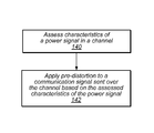
- a method of suppressing interference in a communication sent over a power signal includes assessing characteristics of a power signal in a channel and applying pre-distortion to a communication signal sent over the channel. The pre-distortion is based on the assessed characteristics of the power signal.
- a system in an embodiment, includes a processor and a memory coupled to the processor.
- the memory program instructions are executable by the processor to implement assessing characteristics of a power signal in a channel and applying pre-distortion to a communication signal sent over the channel. The pre-distortion is based on the assessed characteristics of the power signal.
- a non-transitory, computer-readable storage medium includes program instructions stored thereon.
- the program instructions implement assessing characteristics of a power signal in a channel and applying pre-distortion to a communication signal sent over the channel.
- the pre-distortion is based on the assessed characteristics of the power signal.
- a method of transmitting power includes assessing characteristics of channel-induced modulation in a power signal, and applying pre-distortion to the power signal to condition the power signal.
- the pre-distortion is based on the assessed characteristics of the channel-induced modulation.
- an electrical power system includes one or more electrical power sources that supply electrical power, and one or more electrical power lines that transmit electrical power from the electrical power source to one or more loads, a processor, and a memory coupled to the processor.
- the memory comprise programs instructions executable to implement assessing characteristics of channel-induced modulation in a power signal, and applying pre-distortion to the power signal to condition the power signal. The pre-distortion is based on the assessed characteristics of the channel-induced modulation.
- a non-transitory, computer-readable storage medium includes program instructions stored thereon.
- the program instructions implement assessing characteristics of channel-induced modulation in a power signal, and applying pre-distortion to the power signal to condition the power signal.
- the pre-distortion is based on the assessed characteristics of the channel-induced modulation.
- FIG. 1 is a graph illustrating the presence of images in a channel.
- FIG. 2 is a graph of magnitude versus frequency further illustrating images or sidelobes and amplitude modulation of a reactive channel.
- FIG. 3 illustrates one embodiment of applying a pre-distortion to suppress interference in a channel.
- FIG. 4 illustrates one embodiment of interference suppression in power line communications using pre-distortion of a communication signal.
- FIG. 5 illustrates effects of pre-distortion in a frequency-domain plot.
- FIG. 6 illustrates a power signal and a coherent amplitude modulation based on the power signal.
- FIG. 7 illustrates an estimated channel modulation envelope and a corresponding pre-distortion envelope.
- FIG. 8 illustrates effects of applying pre-distortion to counteract channel effects.
- FIG. 9 illustrates signals prior to introduction into a channel in one embodiment.
- FIG. 10 illustrates one embodiment of a power system that includes a system for applying pre-distortion to power signals.
- FIG. 11 illustrates one embodiment of interference suppression to condition power.
- image includes any image, replication, ghost, shadow, echo, reflection, copy, or byproduct of an original signal (or a portion of an original signal) introduced into a channel.
- An image may be, for example, a replication of a signal introduced into a channel for purposes of communication.
- An image may include changes in magnitude (increases or decreases) in a signal that are, in the aggregate, observable within a range of frequencies. For example, an image may be observable in frequency domain as a notch, spike, or lobe (such as in a plot of magnitude versus frequency for a signal).
- An image may be harmonically related to one or more elements of the original signal, a fundamental on the channel, or both.
- images may be observable as lobes at 120 Hz offsets from an 1100 Hz carrier frequency for a communication signal (the offsets in this example being twice the fundamental frequency).
- An image may be characterized by a smooth rise and fall or a by series or set of irregular rises and falls in a signal.
- pre-distortion means any distortion, modulation, alteration, or modification of a signal before, or at the time, a signal is introduced into a given channel or medium.
- real-time in the context of a system performing a computation for electrical signal transmission or signal processing, includes any computation that occurs while signals are being processed by the system.
- a real-time update may take perceptible amount of time to be completed, but would not involve, for example, transmission or processing being switched off during a computation.
- signal characteristics of a power line are observed and used to pre-distort communication signals prior to the communication signals' introduction to the power line channel.
- suppression is performed in low-frequency, narrowband power line communications.
- time-varying characteristics of signals present in a channel prior to introduction of the communication signal are incorporated into an algorithm to pre-distort the communication signal prior to introduction into the channel.
- the pre-distortion may compensate for the channel-induced modulation and suppress the apparent modulation.
- Pre-distortion may produce a cleaner spectral environment after the communication signal is introduced to the channel.
- pre-distortion is used to suppress recursively modulated image signals.
- FIG. 1 is a graph illustrating the presence of images in a channel.
- a 930 Hz subcarrier is introduced into an active power line channel.
- the original 60 Hz power signal is shown at 100 .
- Odd harmonics of the 60 Hz power signal are shown at 102 .
- the injected signal of 930 Hz is shown at 104 .
- Harmonic images of the injected signal at a plus or minus 120 Hz harmonic offset are shown at 106 .
- FIG. 2 is a graph of magnitude versus frequency further illustrating images or sidelobes and amplitude modulation of a reactive channel.
- the plots in FIG. 2 represent a comb-filtered version of FIG. 1 (for example, in which filtering has been applied to remove everything except the 930 Hz communication signal and its images).
- Plot 110 illustrates a short, comb-filtered segment of the 930 Hz pure tone shown in FIG. 1 .
- Side lobes 112 are shown at plus or minus 120 Hz-harmonic offset from injected signal 114 .
- a communication signal in a channel is pre-distorted prior to introduction to the channel to suppress channel-initiated interference from the power line.
- FIG. 3 illustrates one embodiment, of applying a pre-distortion process to suppress interference in a channel.
- one or more characteristics of channel-induced modulation in a channel are assessed.
- the characteristics include one or more images.
- the characteristics include voltage of a signal in the channel.
- a basis set used within the pre-distortion algorithm is computed in real-time from time-domain samples of the channel power signal and used to create a pre-distortion characteristic which can be applied to the communication signal prior to introduction to the channel.
- pre-distortion is applied to a signal sent over the channel.
- the pre-distortion may be based on the assessed characteristics of the channel-induced modulation.
- a phase-coherent amplitude envelope is determined from characteristics of the power signal, which may include images of the communication signal.
- the amplitude envelope may include an inversion based on one or more of the images.
- the pre-distorted signal may, for example, match and counteract (or, be an “inverse” of) the amplitude distortion that will be induced by the channel.
- the specific structure of the pre-distortion signal may be estimated from a function of the signals on the channel.
- the distortion may be phase-synchronous with the fundamental, so the form of the pre-distortion envelope may be derived as a linear combination of powers of the fundamental.
- the pre-distortion function or “inverse envelope” can be computed instantaneously from observed samples of the fundamental.
- the method may observe the extant voltage on the power network and, using the formulation of the distortion envelope, compute a pre-distortion function which can be imposed on the communication signal just prior to introduction to the power network.
- a pre-distortion envelope may be a close approximation of the inverse of the amplitude distortion envelope imposed by the power network.
- suppression of interference in a channel includes determining a phase-coherent amplitude envelope.
- the phase-coherent amplitude envelope may be applied to the communication signal prior to introduction to the channel.
- the pre-distortion amplitude envelope may be related to the existing (distorted) amplitude envelope.
- the pre-distortion envelope may be created by observing the idle-channel signal which is already-present in the channel.
- a communication signal over a power line is pre-distorted to suppress interference in a power line.
- FIG. 4 illustrates one embodiment of interference suppression in power line communications using pre-distortion of a communication signal.
- the power signal may be a signal on a power transmission line from a power utility.
- the fundamental frequency of the power line may be, for example, 60 Hz.
- pre-distortion may be applied to a communication signal sent over the channel based on the assessed characteristics of the power signal.
- the communication includes messages over a smart grid.
- the amplitude of the pre-distorted signal may be an inversion of the amplitude distortion induced by the power network.
- time-domain samples of the idle-channel signal are transformed to create a basis set.
- the basis set may be linearly combined to produce the pre-distortion envelope.
- the basis set used for the weighted linear combination is a truncated set of odd powers of the power signal itself, including the fundamental, its harmonics, and any noise present on the channel (a “coherent basis”).
- the basis set may be neither normalized nor orthogonal, but can be computed instantaneously from time-domain samples of the idle-channel power signal. Any requirement for a secondary phase-locking subsystem may be eliminated.
- Coefficients used in the weighted linear combination and the truncation (order) of the sum can be pre-determined statically or updated dynamically.
- a forward-adaptive (frame-wise) approach may be used to determine the coefficient and/or the order.
- a backward-adaptive (sample-wise) approach may be used to determine the coefficient and/or the order.
- the coefficients can also be optimized in the spectral domain (for example, using a sinusoidal basis set) and then transformed for use with the coherent basis set using a power reduction formula, or vice versa.
- FIG. 5 illustrates effects of pre-distortion in a frequency-domain plot.
- the counteracting time-domain envelope has been computed from the idle-channel signal and applied to the communication signal prior to introduction to the channel.
- Plot 162 is a plot in which sidelobes have been suppressed using pre-distortion.
- An example of suppression of the side lobes can be seen, for example, around the first image at 166 & 168 (f c ⁇ 120 Hz). In this case, a pre-distortion gain is roughly 20 dB.
- This pre-distortion gain is also evident at several other image locations (f c ⁇ n*120 Hz), as can be seen in the differential between plot 160 and plot 162 in areas 164 , 166 , 168 , and 170 .
- the spectral envelope of the original communication signal around 930 Hz may be relatively undistorted even after the pre-distortion process and the coherent distortion process (the channel).
- the lack of distortion is an indicator of efficacy of the pre-distortion process because the communication signal passes into the channel with maximum efficiency while minimizing the distortion due to images or sidelobes, (which occur naturally in this reactive channel).
- a set of basis functions are created from an observation of the fundamental. These basis functions may be combined and used to calculate the pre-distortion envelope, which is then applied to the communication signal. If the set of basis functions and their combination are close enough to the unknown process creating amplitude distortion in the channel, then the two effects will counteract each other, leaving the communication signal in the channel, undistorted.
- the amplitude modulation induced by the channel may be phase-coherent with the fundamental. Further, the amplitude modulation envelope imposed on any signal in the channel can be estimated by a linear combination of specific functions of the fundamental.
- p the entire power signal observed in the channel, which is largely sinusoidal but which may contain some harmonic content due to channel-induced distortion.
- s might be a sinusoid at some frequency other than 60 Hz.
- s might be a more complex pass-band carrier, modulated via analog or digital means to carry a message signal or data bits.
- An objective is to transmit communication signal s through the power line system so that the resulting signal can be recovered without error.
- the power line system may distort s via an unknown transfer function H p . Due to the nature of the system, the transfer function may not affect the power signal p.
- the transfer function H p may depend on p in some fashion, and the structure of H p can be partially estimated via observation of p. Since the effect of H p may be similar to conventional amplitude modulation, appropriate pre-distortion of s via an inverse-function H p ⁇ 1 may effectively cancel out the effect of the channel, thereby suppressing unwanted noise or spectral artifacts related to the interaction of s, p, and H p .
- H p ( H p ⁇ 1 ( s )) s. (1)
- H p may be unknown and may not be observed effectively. As such, computing H p ⁇ 1 precisely may not be possible.
- the channel may produce a coherent amplitude modulation of secondary signals such as s.
- This coherent amplitude modulation can be partially modeled using a linear combination of p j , or
- Equation (3) q(t) is composed using the basis set which is odd powers of the signal p(t).
- the model q(t) can equivalently be composed using a basis set which is even powers of p(t) or a combination of odd and even powers of p(t).
- FIG. 6 A representative p(t) and q(t) are shown in FIG. 6 , where q(t) is constructed using the odd-power basis set only.
- Plot 200 represents p and plot 202 represents q.
- the coefficients were estimated manually.
- both p and q are normalized to unit amplitude.
- the channel may construct a “false message” which is imposed on communication signal s as it transits the channel.
- Equation 4 the real “false message” H p is estimated by ⁇ p , which depends on q through coefficients ⁇ .
- the “false message” can be counteracted by pre-distorting s with ⁇ p ⁇ 1 .
- All envelope functions may be normalized to unit amplitude prior to use.
- ⁇ is a constant related to the modulation depth, as is customary for amplitude modulation envelopes.
- a representative H p estimated from an actual power signal p(t) is shown in FIG. 7 .
- an estimated channel module envelope H p is represented by plot 210 and a corresponding pre-distortion envelope is represented by plot 212 .
- the communication signal s may be a low-rate BPSK-modulated sinusoidal carrier with frequency of roughly 900 Hz.
- FIG. 8 subtle amplitude modulation effects of H p on s may be seen.
- the amplitude envelope of s H which is due to H p , has notches that may be coherent with the peaks of the fundamental p.
- time-domain artifacts are implicitly modeled by q (and hence ⁇ p ).
- the envelope can be translated to an optimized pre-distortion implementation that does not require complex feedback loops or phase discrimination/locking techniques.
- the modulation imposed by the channel via H p is pre-distorted by an inverse function.
- the pre-distortion approach may involve estimating and optimizing the coefficients of q and then formulating an “estimated false message” signal ⁇ p , which can be applied to s prior to introduction to the channel as ⁇ p ⁇ 1 (s).
- the channel transfer function may re-impose the “false message” H p onto the pre-distorted signal.
- the distortion due to the channel can be moderated as in Equation 2, subject to the fidelity of q, ⁇ , and hence ⁇ p .
- a representative graph of the outcome of this process is shown in FIG. 8 . In FIG.
- plot 220 represents a channel envelope corresponding to the channel-induced modulation of signal H p (s).
- Plot 222 represents a pre-distorted signal ⁇ p ⁇ 1 (s) introduced into the channel.
- Plot 224 represents a resulting suppressed signal ⁇ .
- the relatively uniform amplitude of in the resultant signal indicates the effectiveness of the pre-distorted signal in counteracting the channel effects seen in plot 220 of the channel envelope.
- the pre-distortion envelope ⁇ p ⁇ 1 and the coefficients ⁇ may be optimized so that ⁇ ⁇ s.
- the form of H p may need to be estimated via, for example, the coefficients of q.
- the pre-distortion envelope ⁇ p ⁇ 1 may be used in a “double sideband” amplitude modulation scenario, and normalized to unit amplitude before use.
- a formulaic representation of ⁇ p ⁇ 1 is:
- a representative envelope is shown in FIG. 7 at plot 212 , and the effect of applying the envelope to a communication signal s is shown in FIG. 8 , plot 224 .
- the coefficients ⁇ may be estimated manually. However, even with non-optimal coefficients, the fidelity of the pre-distortion process which suppresses the unwanted image energy via an estimate of H p in this example may be relatively effective, as illustrated in plot 224 in FIG. 8 ( ⁇ ) and the spectral plot in FIG. 5 .
- Estimation and inversion of the “false message” includes performing an optimization that depends on a set of coefficients ⁇ . Any suitable approach may be used for optimizing coefficients of this form. In some instances, the signal p may change slowly over time. In these cases, the introduction of a windowed or framed approach may be optimal.
- the effect of the coherent, channel induced distortion is represented in the amplitude envelope of plot 220 , and the pre-distorted signal fed to the channel is represented by plot 222 , and resulting suppressed signal is represented by plot 224 .
- the notches in the amplitude of H p (s) may be phase-coherent with the peaks of p.
- plot 222 the corresponding inverse amplitude modulation of s due to ⁇ p ⁇ 1 is seen.
- the peaks in the amplitude of ⁇ p ⁇ 1 (s) may be phase-coherent with the peaks of p, and hence are also phase-coherent with the notches in H p (s).
- FIG. 5 The effect of this process is illustrated in FIG. 5 where the original spectrum of the power line channel is displayed using a dotted line, and the pre-distorted spectrum is displayed using a solid line.
- a low-rate BPSK signal s is introduced to the channel with a carrier frequency near 900 Hz.
- the pre-distortion scheme is not used (dotted line)
- the images or “sidelobes” of the introduced signal are clearly evident at 120 Hz harmonic offsets from the carrier.
- the pre-distortion scheme is used, the images of s have been suppressed significantly (solid line).
- the differential distortion between the original communication signal s and the post-received, pre-distorted signal ⁇ is approximately 0.7 dB.
- Two areas which may be further optimized in some embodiments include: (a) spurious peaks at distant 120 Hz harmonic offsets from the 900 Hz carrier, and (b) a slowly varying spectral envelope.
- a near-field suppression approach as described herein is used in which coefficients are continuously re-optimized.
- Near-field suppression as described herein may be used, in certain embodiments, in transmissions schemes that rely on large numbers of “thin” carriers, such as frequency-division modulation (FDM) or computationally efficient equivalent approaches based on transforms, such as orthogonal FDM (OFDM).
- FDM frequency-division modulation
- OFDM orthogonal FDM
- FIG. 9 illustrates signals prior to introduction into a channel according to one embodiment.
- Plot 230 represents an original signal before pre-distortion.
- Plot 232 represents an estimated inverse channel envelope.
- Plot 232 may correspond to, for example, an inversion of the channel envelope represented by plot 220 shown in FIG. 8 .
- Plot 234 represents a pre-distorted signal.
- the pre-distorted signal of plot 234 may be generated by applying the inverse channel envelope of plot 232 to the original signal of plot 230 .
- the process of formulating a set of coefficients and truncating the approximation involves using unity-valued coefficients for the first N, and the remainder coefficients zero-valued.
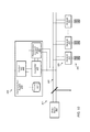
- FIG. 10 illustrates one embodiment of a power system that includes a system for applying pre-distortion to power signals.
- System 300 includes power source 304 and user systems 306 .
- Power source 304 may produce electrical power and supply it to user systems 306 by way of power transmission lines 308 .
- Power source 304 may be, for example, a utility power plant.
- Communication system 310 may introduce signals onto power transmission lines 308 .
- Communication system may transmit signals over power lines 308 to receivers 312 in user systems 306 .
- receivers can be embedded in devices owned by the utility company, or which are part of the grid infrastructure (for example, instead of, or addition to, those in“user systems”).
- Communication system 310 includes control unit 320 , transmitter 322 , data storage device 324 , and pre-distortion compute module 326 .
- Control unit 320 may access and store data on data storage device 324 .
- Control unit 320 may control transmitter 322 to generate communication signals over power lines 308 .
- Pre-distortion compute module 326 may sense power signals carried over power transmission lines 308 .
- Control unit 320 may control pre-distortion compute module 326 to compute envelopes for generating pre-distortion to be applied to signals from transmitter 322 .
- communication system 310 is described for illustrative purposes as only sending communication signals, and receivers 312 are described as only receiving signals. In some embodiments, nevertheless, some or all of the devices in a network may both send and receive communications signals over power lines. In some embodiments, devices in a smart grid use pre-distortion as described herein to suppress interference in communication signals sent over power lines.
- a power signal transmitted over a power line is pre-distorted to condition the power being transmitted.
- FIG. 11 illustrates one embodiment of interference suppression to condition power.
- the power signal may be a signal on a power transmission line from a power utility.
- the fundamental frequency of the power line may be, for example, 60 Hz.
- pre-distortion may be applied to the power signal to condition the power signal based on the assessed characteristics of the power signal. Conditioning may improve the quality of power being transmitted to various electrical loads.
- the pre-distorted signal is an inversion of the amplitude distortion induced by the power network.
- Pre-distortion of signals as described above may provide enhanced Power Line Communications (PLC) capability by suppression of power line signal interference, thus enabling more efficient and reliable use of the power line for additional communication signals, such as for smart grid applications.
- PLC Power Line Communications
- this technology would be considered a Smart Grid-Enabling Technology, targeting the integrated communications segment, specifically enabling enhanced power line communication
- Applications that may implement image suppression using pre-distortion include energy management systems (residential, commercial, or industrial), smart metering applications, manufacturing (for example, semiconductor manufacturing), and home area network (including, for example, enhanced communication with smart appliances in the home).
- Other applications that may implement image suppression using pre-distortion include, in various embodiments, electric vehicle (EV) charging applications. Examples include remote monitoring of EV charging and automated load balancing to enable efficient EV charging.
- EV electric vehicle
- Computer systems may, in various embodiments, include components such as a CPU with an associated memory medium such as Compact Disc Read-Only Memory (CD-ROM).
- the memory medium may store program instructions for computer programs.
- the program instructions may be executable by the CPU.
- Computer systems may further include a display device such as monitor, an alphanumeric input device such as keyboard, and a directional input device such as mouse.
- Computing systems may be operable to execute the computer programs to implement computer-implemented systems and methods.
- a computer system may allow access to users by way of any browser or operating system.
- Embodiments of a subset or all (and portions or all) of the above may be implemented by program instructions stored in a memory medium or carrier medium and executed by a processor.
- a memory medium may include any of various types of memory devices or storage devices.
- the term “memory medium” is intended to include an installation medium, e.g., a Compact Disc Read Only Memory (CD-ROM), floppy disks, or tape device; a computer system memory or random access memory such as Dynamic Random Access Memory (DRAM), Double Data Rate Random Access Memory (DDR RAM), Static Random Access Memory (SRAM), Extended Data Out Random Access Memory (EDO RAM), Rambus Random Access Memory (RAM), etc.; or a non-volatile memory such as a magnetic media, e.g., a hard drive, or optical storage.
- DRAM Dynamic Random Access Memory
- DDR RAM Double Data Rate Random Access Memory
- SRAM Static Random Access Memory
- EEO RAM Extended Data Out Random Access Memory
- RAM Rambus Random Access Memory
- the memory medium may comprise other types of memory as well, or combinations thereof.
- the memory medium may be located in a first computer in which the programs are executed, or may be located in a second different computer that connects to the first computer over a network, such as the Internet. In the latter instance, the second computer may provide program instructions to the first computer for execution.
- the term “memory medium” may include two or more memory mediums that may reside in different locations, e.g., in different computers that are connected over a network.
- a computer system at a respective participant location may include a memory medium(s) on which one or more computer programs or software components according to one embodiment may be stored.
- the memory medium may store one or more programs that are executable to perform the methods described herein.
- the memory medium may also store operating system software, as well as other software for operation of the computer system.
- the memory medium may store a software program or programs operable to implement embodiments as described herein.
- the software program(s) may be implemented in various ways, including, but not limited to, procedure-based techniques, component-based techniques, and/or object-oriented techniques, among others.
- the software programs may be implemented using ActiveX controls, C++ objects, JavaBeans, Microsoft Foundation Classes (MFC), browser-based applications (e.g., Java applets), traditional programs, or other technologies or methodologies, as desired.
- a CPU executing code and data from the memory medium may include a means for creating and executing the software program or programs according to the embodiments described herein.
Landscapes
- Engineering & Computer Science (AREA)
- Computer Networks & Wireless Communication (AREA)
- Signal Processing (AREA)
- Power Engineering (AREA)
- Cable Transmission Systems, Equalization Of Radio And Reduction Of Echo (AREA)
Abstract
Description
H p(H p −1(s))=s. (1)
H p(H p −1(s))=ŝ≈s. (2)
where coefficients α=(α1, . . . , αn)T are initially unknown and may be optimized for each instance of the channel, or re-optimized over time. In Equation (3), q(t) is composed using the basis set which is odd powers of the signal p(t). The model q(t) can equivalently be composed using a basis set which is even powers of p(t) or a combination of odd and even powers of p(t). A representative p(t) and q(t) are shown in
Ĥ p(t,α)=−|q(t)|+δ. (4)
where α=(α1, . . . , αn)T, ε>0, and MAX(.) is the maximum value of the numerator to ensure unity amplitude. A representative envelope is shown in
| TABLE 1 | |||||||
| N | alpha(1) | alpha(2) | alpha(3) | alpha(4) | alpha(5) | alpha(6) | alpha(7) |
| 1 | 1 | ||||||
| 2 | 1.0e−06* | 1.0e−06* | |||||
| (−0.2267354 | (−0.33701498 | ||||||
| 74435443) | 5986362) | ||||||
| 3 | −0.0000289 | 0.00008906 | 0.00169273 | ||||
| 98013682 | 8579453 | 3301065 | |||||
| 4 | 0.0319640 | 0.01899495 | 0.01251511 | 0.01496078 | |||
| 17187134 | 9890008 | 7498110 | 8673542 | ||||
| 5 | −0.0293630 | 0.05841419 | 0.00585579 | −0.03138356 | 0.03792582 | ||
| 96903303 | 6420801 | 6233263 | 7947181 | 4459968 | |||
| 6 | 0.0551020 | −0.15770467 | 0.39724956 | −0.48277577 | 0.23433627 | 0.00135230 | |
| 39334367 | 0758027 | 2827227 | 5931498 | 3787741 | 7313303 | ||
| 7 | 0.0358386 | −0.11940271 | 0.25919593 | −0.25935201 | 0.06605608 | 0.04322283 | −0.22336 |
| 51996427 | 4503254 | 4681300 | 4188269 | 7457890 | 2780858 | 6530973 | |
| 619 | |||||||
Claims (29)
Applications Claiming Priority (1)
| Application Number | Priority Date | Filing Date | Title |
|---|---|---|---|
| PCT/US2012/049296 WO2014021895A1 (en) | 2012-08-02 | 2012-08-02 | Suppression of interference in power and communication signals |
Publications (2)
| Publication Number | Publication Date |
|---|---|
| US20160049988A1 US20160049988A1 (en) | 2016-02-18 |
| US9876516B2 true US9876516B2 (en) | 2018-01-23 |
Family
ID=50028396
Family Applications (1)
| Application Number | Title | Priority Date | Filing Date |
|---|---|---|---|
| US14/419,152 Active US9876516B2 (en) | 2012-08-02 | 2012-08-02 | Suppression of interference in power and communications signals |
Country Status (2)
| Country | Link |
|---|---|
| US (1) | US9876516B2 (en) |
| WO (1) | WO2014021895A1 (en) |
Families Citing this family (1)
| Publication number | Priority date | Publication date | Assignee | Title |
|---|---|---|---|---|
| CN106651150B (en) * | 2016-12-01 | 2021-02-09 | 全球能源互联网研究院有限公司 | Method and device for evaluating harmonic influence of power grid |
Citations (16)
| Publication number | Priority date | Publication date | Assignee | Title |
|---|---|---|---|---|
| US5911115A (en) * | 1995-03-31 | 1999-06-08 | Intel Corporation | Data transmission over amps networks |
| WO2004054117A2 (en) | 2002-12-10 | 2004-06-24 | Current Technologies, Llc | A Power Line Communication System and Method of Operating the Same |
| US6961373B2 (en) | 2002-07-01 | 2005-11-01 | Solarflare Communications, Inc. | Method and apparatus for channel equalization |
| US7113491B2 (en) | 2001-07-31 | 2006-09-26 | Conexant, Inc. | Method and system for varying an echo canceller filter length based on data rate |
| US7352687B2 (en) | 2003-04-28 | 2008-04-01 | Solarflare Communications, Inc. | Mixed domain cancellation |
| US7567666B2 (en) | 2002-11-07 | 2009-07-28 | Solarflare Communications, Inc. | Method and apparatus for crosstalk mitigation |
| US20090307540A1 (en) * | 2008-06-06 | 2009-12-10 | Maxim Integrated Products, Inc. | System and method for applying multi-tone ofdm based communications within a prescribed frequency range |
| US20100159855A1 (en) * | 2008-12-19 | 2010-06-24 | Sony Corporation, Inc. | Techniques for pre-distorting transmitted signals for a transmitter device |
| US20100187914A1 (en) | 2009-01-26 | 2010-07-29 | Geneva Cleantech Inc. | Methods and apparatus for power factor correction and reduction of distortion in and noise in a power supply delivery network |
| US20100283540A1 (en) | 2009-05-07 | 2010-11-11 | Nortel Networks, Limited | Pre-distortion for a Radio Frequency Power Amplifier |
| US7834643B2 (en) * | 2008-03-28 | 2010-11-16 | Baker Hughes Incorporated | Systems and methods for reducing distortion in a power source using an active harmonics filter |
| US20100322364A1 (en) | 2007-03-12 | 2010-12-23 | Bogdan John W | Noise Filtering Inverse Transformation |
| US20110075754A1 (en) | 2007-09-06 | 2011-03-31 | Smith Francis J | Mitigation of transmitter passive and active intermodulation products in real and continuous time in the transmitter and co-located receiver |
| US7948862B2 (en) | 2007-09-26 | 2011-05-24 | Solarflare Communications, Inc. | Crosstalk cancellation using sliding filters |
| US20110163806A1 (en) | 2008-09-09 | 2011-07-07 | Naoki Hongo | Distortion compensation amplification device |
| US20120207229A1 (en) * | 2011-02-16 | 2012-08-16 | Analog Devices, Inc. | Digital pre-distortion |
-
2012
- 2012-08-02 WO PCT/US2012/049296 patent/WO2014021895A1/en not_active Ceased
- 2012-08-02 US US14/419,152 patent/US9876516B2/en active Active
Patent Citations (16)
| Publication number | Priority date | Publication date | Assignee | Title |
|---|---|---|---|---|
| US5911115A (en) * | 1995-03-31 | 1999-06-08 | Intel Corporation | Data transmission over amps networks |
| US7113491B2 (en) | 2001-07-31 | 2006-09-26 | Conexant, Inc. | Method and system for varying an echo canceller filter length based on data rate |
| US6961373B2 (en) | 2002-07-01 | 2005-11-01 | Solarflare Communications, Inc. | Method and apparatus for channel equalization |
| US7567666B2 (en) | 2002-11-07 | 2009-07-28 | Solarflare Communications, Inc. | Method and apparatus for crosstalk mitigation |
| WO2004054117A2 (en) | 2002-12-10 | 2004-06-24 | Current Technologies, Llc | A Power Line Communication System and Method of Operating the Same |
| US7352687B2 (en) | 2003-04-28 | 2008-04-01 | Solarflare Communications, Inc. | Mixed domain cancellation |
| US20100322364A1 (en) | 2007-03-12 | 2010-12-23 | Bogdan John W | Noise Filtering Inverse Transformation |
| US20110075754A1 (en) | 2007-09-06 | 2011-03-31 | Smith Francis J | Mitigation of transmitter passive and active intermodulation products in real and continuous time in the transmitter and co-located receiver |
| US7948862B2 (en) | 2007-09-26 | 2011-05-24 | Solarflare Communications, Inc. | Crosstalk cancellation using sliding filters |
| US7834643B2 (en) * | 2008-03-28 | 2010-11-16 | Baker Hughes Incorporated | Systems and methods for reducing distortion in a power source using an active harmonics filter |
| US20090307540A1 (en) * | 2008-06-06 | 2009-12-10 | Maxim Integrated Products, Inc. | System and method for applying multi-tone ofdm based communications within a prescribed frequency range |
| US20110163806A1 (en) | 2008-09-09 | 2011-07-07 | Naoki Hongo | Distortion compensation amplification device |
| US20100159855A1 (en) * | 2008-12-19 | 2010-06-24 | Sony Corporation, Inc. | Techniques for pre-distorting transmitted signals for a transmitter device |
| US20100187914A1 (en) | 2009-01-26 | 2010-07-29 | Geneva Cleantech Inc. | Methods and apparatus for power factor correction and reduction of distortion in and noise in a power supply delivery network |
| US20100283540A1 (en) | 2009-05-07 | 2010-11-11 | Nortel Networks, Limited | Pre-distortion for a Radio Frequency Power Amplifier |
| US20120207229A1 (en) * | 2011-02-16 | 2012-08-16 | Analog Devices, Inc. | Digital pre-distortion |
Non-Patent Citations (3)
| Title |
|---|
| International Preliminary Report on Patentability dated Feb. 3, 2015. |
| International Search Report/Written Opinion for PCT Application No. PCT/US2012/049296 dated Mar. 4, 2013. |
| Nelder et al. "A simplex method for function minimization," Computer Journal, vol. 7, pp. 308-313, 1965. |
Also Published As
| Publication number | Publication date |
|---|---|
| US20160049988A1 (en) | 2016-02-18 |
| WO2014021895A1 (en) | 2014-02-06 |
Similar Documents
| Publication | Publication Date | Title |
|---|---|---|
| US10477031B2 (en) | System and method for suppression of non-linear acoustic echoes | |
| CN103378908B (en) | A kind of nonlinear impairments compensation method of intensity modulated direct-detection system and device | |
| WO2012092647A1 (en) | A method and system for linearising a radio frequency transmitter | |
| US8589329B2 (en) | Method and apparatus for incremental tracking of multiple quantiles | |
| US20160309042A1 (en) | Echo cancellation | |
| US10116407B2 (en) | System and method for improving narrowband interference performance | |
| US20230049687A1 (en) | Systems and Methods for Shaped Single Carrier Orthogonal Frequency Division Multiplexing with Low Peak to Average Power Ratio | |
| US9876516B2 (en) | Suppression of interference in power and communications signals | |
| US7817733B2 (en) | Method and system for peak power reduction | |
| US20140079232A1 (en) | Audio processing device, audio processing method, and recording medium recording audio processing program | |
| Hadj Ali et al. | Low-complexity PAPR reduction method based on the TLBO algorithm for an OFDM signal | |
| Zhang et al. | Efficient cross-correlation algorithm for correction of common phase error employing preamble for orthogonal frequency division multiplexing (OFDM) receivers | |
| EP3136667A1 (en) | Adaptive equalizer, adaptive equalization method and receiver | |
| WO2022261549A1 (en) | Systems and methods for shaped single carrier orthogonal frequency division multiplexing with low peak to average power ratio | |
| Hossain et al. | Efficient PAPR reduction in DCT-SCFDMA system based on absolute exponential companding technique with pulse shaping | |
| CN114629750A (en) | Channel estimation enhancement method, device, equipment and medium | |
| CN112073341A (en) | Method and system for estimating self-interference channel of full-duplex digital domain | |
| US11490202B2 (en) | Delay estimation method, echo cancellation method and signal processing device utilizing the same | |
| Pech et al. | A novel method for dominant oscillation estimation and harmony quantification through spectral leakage suppression | |
| Jon et al. | Reduction of signal envelope fluctuations in OFDM systems using ACE with double extension | |
| Lim et al. | Predistorter design for a memory-less nonlinear high power amplifier using the pth-order inverse method for OFDM systems | |
| CN113079452A (en) | Audio processing method, audio direction information generating method, electronic device, and medium | |
| Liu et al. | The Capacity Performance of OFDM Systems with Nonlinear Pulse Blanking in Frequency Selective Fading Channels | |
| Wang et al. | Adaptive digital predistortion based on hybrid indirect learning structure with variable step-size for wideband hpa | |
| CN118764246B (en) | A network scanning method, device, equipment and storage medium |
Legal Events
| Date | Code | Title | Description |
|---|---|---|---|
| AS | Assignment |
Owner name: TEXAS STATE UNIVERSITY - SAN MARCOS, TEXAS Free format text: ASSIGNMENT OF ASSIGNORS INTEREST;ASSIGNOR:MCCLELLAN, STAN;REEL/FRAME:036913/0254 Effective date: 20150421 |
|
| STCF | Information on status: patent grant |
Free format text: PATENTED CASE |
|
| MAFP | Maintenance fee payment |
Free format text: PAYMENT OF MAINTENANCE FEE, 4TH YR, SMALL ENTITY (ORIGINAL EVENT CODE: M2551); ENTITY STATUS OF PATENT OWNER: SMALL ENTITY Year of fee payment: 4 |
|
| MAFP | Maintenance fee payment |
Free format text: PAYMENT OF MAINTENANCE FEE, 8TH YR, SMALL ENTITY (ORIGINAL EVENT CODE: M2552); ENTITY STATUS OF PATENT OWNER: SMALL ENTITY Year of fee payment: 8 |