US9875043B1 - Managing data migration in storage systems - Google Patents
Managing data migration in storage systems Download PDFInfo
- Publication number
- US9875043B1 US9875043B1 US14/674,647 US201514674647A US9875043B1 US 9875043 B1 US9875043 B1 US 9875043B1 US 201514674647 A US201514674647 A US 201514674647A US 9875043 B1 US9875043 B1 US 9875043B1
- Authority
- US
- United States
- Prior art keywords
- logical object
- data
- storage
- logical
- storage pool
- Prior art date
- Legal status (The legal status is an assumption and is not a legal conclusion. Google has not performed a legal analysis and makes no representation as to the accuracy of the status listed.)
- Active, expires
Links
Images


Classifications
-
- G—PHYSICS
- G06—COMPUTING; CALCULATING OR COUNTING
- G06F—ELECTRIC DIGITAL DATA PROCESSING
- G06F3/00—Input arrangements for transferring data to be processed into a form capable of being handled by the computer; Output arrangements for transferring data from processing unit to output unit, e.g. interface arrangements
- G06F3/06—Digital input from, or digital output to, record carriers, e.g. RAID, emulated record carriers or networked record carriers
- G06F3/0601—Interfaces specially adapted for storage systems
- G06F3/0602—Interfaces specially adapted for storage systems specifically adapted to achieve a particular effect
- G06F3/0614—Improving the reliability of storage systems
- G06F3/0619—Improving the reliability of storage systems in relation to data integrity, e.g. data losses, bit errors
-
- G—PHYSICS
- G06—COMPUTING; CALCULATING OR COUNTING
- G06F—ELECTRIC DIGITAL DATA PROCESSING
- G06F3/00—Input arrangements for transferring data to be processed into a form capable of being handled by the computer; Output arrangements for transferring data from processing unit to output unit, e.g. interface arrangements
- G06F3/06—Digital input from, or digital output to, record carriers, e.g. RAID, emulated record carriers or networked record carriers
- G06F3/0601—Interfaces specially adapted for storage systems
- G06F3/0668—Interfaces specially adapted for storage systems adopting a particular infrastructure
- G06F3/0671—In-line storage system
- G06F3/0683—Plurality of storage devices
- G06F3/0689—Disk arrays, e.g. RAID, JBOD
-
- G—PHYSICS
- G06—COMPUTING; CALCULATING OR COUNTING
- G06F—ELECTRIC DIGITAL DATA PROCESSING
- G06F3/00—Input arrangements for transferring data to be processed into a form capable of being handled by the computer; Output arrangements for transferring data from processing unit to output unit, e.g. interface arrangements
- G06F3/06—Digital input from, or digital output to, record carriers, e.g. RAID, emulated record carriers or networked record carriers
- G06F3/0601—Interfaces specially adapted for storage systems
- G06F3/0602—Interfaces specially adapted for storage systems specifically adapted to achieve a particular effect
- G06F3/061—Improving I/O performance
-
- G—PHYSICS
- G06—COMPUTING; CALCULATING OR COUNTING
- G06F—ELECTRIC DIGITAL DATA PROCESSING
- G06F3/00—Input arrangements for transferring data to be processed into a form capable of being handled by the computer; Output arrangements for transferring data from processing unit to output unit, e.g. interface arrangements
- G06F3/06—Digital input from, or digital output to, record carriers, e.g. RAID, emulated record carriers or networked record carriers
- G06F3/0601—Interfaces specially adapted for storage systems
- G06F3/0628—Interfaces specially adapted for storage systems making use of a particular technique
- G06F3/0646—Horizontal data movement in storage systems, i.e. moving data in between storage devices or systems
- G06F3/0647—Migration mechanisms
-
- G—PHYSICS
- G06—COMPUTING; CALCULATING OR COUNTING
- G06F—ELECTRIC DIGITAL DATA PROCESSING
- G06F3/00—Input arrangements for transferring data to be processed into a form capable of being handled by the computer; Output arrangements for transferring data from processing unit to output unit, e.g. interface arrangements
- G06F3/06—Digital input from, or digital output to, record carriers, e.g. RAID, emulated record carriers or networked record carriers
- G06F3/0601—Interfaces specially adapted for storage systems
- G06F3/0628—Interfaces specially adapted for storage systems making use of a particular technique
- G06F3/0662—Virtualisation aspects
- G06F3/0665—Virtualisation aspects at area level, e.g. provisioning of virtual or logical volumes
-
- G—PHYSICS
- G06—COMPUTING; CALCULATING OR COUNTING
- G06F—ELECTRIC DIGITAL DATA PROCESSING
- G06F3/00—Input arrangements for transferring data to be processed into a form capable of being handled by the computer; Output arrangements for transferring data from processing unit to output unit, e.g. interface arrangements
- G06F3/06—Digital input from, or digital output to, record carriers, e.g. RAID, emulated record carriers or networked record carriers
- G06F3/0601—Interfaces specially adapted for storage systems
- G06F3/0668—Interfaces specially adapted for storage systems adopting a particular infrastructure
- G06F3/0671—In-line storage system
- G06F3/0683—Plurality of storage devices
- G06F3/0685—Hybrid storage combining heterogeneous device types, e.g. hierarchical storage, hybrid arrays
Definitions
- This application relates to managing data migration in storage systems.
- Computer systems may include different resources used by one or more host processors. Resources and host processors in a computer system may be interconnected by one or more communication connections. These resources may include, for example, data storage devices such as those included in the data storage systems manufactured by EMC Corporation. These data storage systems may be coupled to one or more servers or host processors and provide storage services to each host processor. Multiple data storage systems from one or more different vendors may be connected and may provide common data storage for one or more host processors in a computer system.
- a traditional storage array (herein also referred to as a “data storage system”, “disk storage array”, “disk array”, or simply “array”) is a collection of hard disk drives operating together logically as a unified storage device.
- Storage arrays are designed to store large quantities of data.
- Storage arrays typically include one or more storage array processors (SPs), for handling requests for allocation and input/output (I/O) requests.
- SPs storage array processors
- An SP is the controller for and primary interface to the storage array.
- a storage array may be thought of as a system for managing a large amount of a resource, i.e., a large number of disk drives.
- Management of the resource may include allocation of a portion of the resource in response to allocation requests.
- portions of the storage array may be allocated to, i.e., exclusively used by, entities that request such allocation.
- Data storage systems such as disk drives, disk storage arrays, network storage devices, storage area networks, and the like, are called upon to store and manage a significant amount of data (e.g., gigabytes, terabytes, petabytes, etc.) that is written and read by many users.
- Storage arrays are typically used to provide storage space for a plurality of computer file systems, databases, applications, and the like. For this and other reasons, it is common for physical storage arrays to be logically partitioned into chunks of storage space, called logical units, or LUs. This allows a unified storage array to appear as a collection of separate file systems, network drives, and/or volumes.
- a host processor may perform a variety of data processing tasks and operations using the data storage system. For example, a host processor may perform basic system I/O operations in connection with data requests, such as data read and write operations.
- Host processor systems may store and retrieve data using a storage device containing a plurality of host interface units, disk drives, and disk interface units.
- the host systems access the storage device through a plurality of channels provided therewith.
- Host systems provide data and access control information through the channels to the storage device and the storage device provides data to the host systems also through the channels.
- the host systems do not address the disk drives of the storage device directly, but rather, access what appears to the host systems as a plurality of logical disk units.
- the logical disk units may or may not correspond to the actual disk drives. Allowing multiple host systems to access the single storage device unit allows the host systems to share data in the device. In order to facilitate sharing of the data on the device, additional software on the data storage systems may also be used.
- a group of fast but small disks may be a fast tier (also referred to as “higher tier” or “high tier”).
- a group of slow but large disks may be a slow tier (also referred to as “lower tier” or “low tier”). It may be possible to have different tiers with different properties or constructed from a mix of different types of physical disks to achieve a performance or price goal. Storing often referenced, or hot, data on the fast tier and less often referenced, or cold, data on the slow tier may create a more favorable customer cost profile than storing all data on a single kind of disk.
- a storage tier may be made up of different types of disks, i.e., disks with different RAID levels, performance and cost characteristics.
- RAID Redundant Array of Independent or Inexpensive Disks
- the first level, RAID-0 combines two or more drives to create a larger virtual disk.
- one disk contains the low numbered sectors or blocks and the other disk contains the high numbered sectors or blocks, forming one complete storage space.
- RAID-0 systems generally interleave the sectors of the virtual disk across the component drives, thereby improving the bandwidth of the combined virtual disk. Interleaving the data in that fashion is referred to as striping.
- RAID-0 systems provide no redundancy of data, so if a drive fails or data becomes corrupted, no recovery is possible short of backups made prior to the failure.
- RAID-1 systems include one or more disks that provide redundancy of the virtual disk.
- One disk is required to contain the data of the virtual disk, as if it were the only disk of the array.
- One or more additional disks contain the same data as the first disk, providing a “mirror” of the data of the virtual disk.
- a RAID-1 system will contain at least two disks, the virtual disk being the size of the smallest of the component disks.
- a disadvantage of RAID-1 systems is that a write operation must be performed for each mirror disk, reducing the bandwidth of the overall array.
- the first disk and the second disk contain the same sectors or blocks, each disk holding exactly the same data.
- RAID-2 systems provide for error correction through hamming codes.
- the component drives each contain a particular bit of a word, or an error correction bit of that word.
- RAID-2 systems automatically and transparently detect and correct single-bit defects, or single drive failures, while the array is running. Although RAID-2 systems improve the reliability of the array over other RAID types, they are less popular than some other systems due to the expense of the additional drives, and redundant onboard hardware error correction.
- RAID-4 systems are similar to RAID-0 systems, in that data is striped over multiple drives. For example, the storage spaces of two disks are added together in interleaved fashion, while a third disk contains the parity of the first two disks.
- RAID-4 systems are unique in that they include an additional disk containing parity. For each byte of data at the same position on the striped drives, parity is computed over the bytes of all the drives and stored to the parity disk. The XOR operation is used to compute parity, providing a fast and symmetric operation that can regenerate the data of a single drive, given that the data of the remaining drives remains intact.
- RAID-3 systems are essentially RAID-4 systems with the data striped at byte boundaries, and for that reason RAID-3 systems are generally slower than RAID-4 systems in most applications.
- RAID-4 and RAID-3 systems therefore are useful to provide virtual disks with redundancy, and additionally to provide large virtual drives, both with only one additional disk drive for the parity information. They have the disadvantage that the data throughput is limited by the throughput of the drive containing the parity information, which must be accessed for every read and write operation to the array.
- RAID-5 systems are similar to RAID-4 systems, with the difference that the parity information is striped over all the disks with the data.
- first, second, and third disks may each contain data and parity in interleaved fashion. Distributing the parity data generally increases the throughput of the array as compared to a RAID-4 system.
- RAID-5 systems may continue to operate though one of the disks has failed.
- RAID-6 systems are like RAID-5 systems, except that dual parity is kept to provide for normal operation if up to the failure of two drives.
- RAID 1+0 provides a concatenated file system that is also redundant.
- the first and second disks are mirrored, as are the third and fourth disks.
- the combination of the mirrored sets forms a storage space that is twice the size of one individual drive, assuming that all four are of equal size.
- Many other combinations of RAID systems are possible.
- Data storage systems such as disk drives, disk storage arrays, network storage devices, storage area networks, and the like, are called upon to store and manage a significant amount of data (e.g., gigabytes, terabytes, petabytes, etc.) that is written and read by many users.
- a traditional storage array may include a collection of hard disk drives operating together logically as a unified storage device.
- Storage arrays are typically used to provide storage space for a plurality of computer file systems, databases, applications, and the like. For this and other reasons, it is common for physical storage arrays to be logically partitioned into chunks of storage space, called logical units, or LUs. This allows a unified storage array to appear as a collection of separate file systems, network drives, and/or volumes.
- the unused space cannot be simply given back to a common storage pool where it may become accessible to other users.
- a database installation may require many terabytes of storage over the long term even though only a small fraction of that space may be needed when the database is first placed into operation.
- the large storage space may eventually be needed, but it is not known exactly when the entire space will be required.
- the allocated storage space lies unused by the requested user and may not be utilized by any other user.
- a sparsely populated logical unit such as a mapped LUN (e.g., thin logical unit (TLU), direct logical unit (DLU))
- TLU thin logical unit
- DLU direct logical unit
- a TLU resolves this problem by allocating the storage space (e.g., making the memory space physically available) as it is needed when (or shortly before) data is written to the TLU.
- a TLU is created from a common pool of physical space and starts with minimal amount of physical space. As the application that is using the TLU starts to demand more storage, the TLU incrementally requests the storage space from the common storage pool in portions referred to as slices.
- data storage systems typically arrange the data and metadata of file systems in blocks of storage.
- the file data constituting files in a file system are stored in blocks of storage, as are inodes, indirect blocks, and other metadata.
- Data storage systems may provision storage to file systems in units of fixed size, here called “slices.”
- Data storage systems may generate slices, for example, from one or more physical storage devices, such as RAID groups of physical storage devices.
- Some data storage systems provide thinly provisioned file systems that are organized based on sparsely populated logical unit such as mapped LUNs. Thinly provisioned file systems typically have very large address spaces but allocate specific storage slices to populate file systems only as storage is needed to satisfy write requests. A thinly provisioned file system may thus have an address space that is measured in petabytes but may allocate slices to occupy only a small fraction of the address space.
- a method is used in managing data migration in storage systems.
- a request to migrate data of a logical object from a source storage pool to a destination storage pool is received.
- the data of the logical object is mapped to a mapped logical object created in the destination storage pool.
- the data of the logical object is relocated to storage space allocated in the destination storage pool. Mappings of the mapped logical object are updated to refer to the data relocated to the storage space allocated in the destination storage pool.
- FIGS. 1-2 are examples of an embodiment of a computer system that may utilize the techniques described herein;
- FIG. 3 is an example illustrating storage device layout
- FIGS. 4-5 are block diagrams illustrating in more detail components that may be used in connection with techniques herein;
- FIGS. 6A-6G are simplified block diagrams of an exemplary system for managing migration of logical objects in a data storage system according to an embodiment of the techniques described herein;
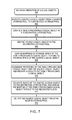
- FIG. 7 is a flow diagram illustrating processes that may be used in connection with techniques herein.
- Described below is a technique for use in managing data migration in storage systems, which technique may be used to provide, among other things, receiving a request to migrate data of a logical object from a source storage pool to a destination storage pool, mapping the data of the logical object to a mapped logical object created in the destination storage pool, and relocating the data of the logical object to storage space allocated in the destination storage pool, where mappings of the mapped logical object is updated to refer to the data relocated to the storage space allocated in the destination storage pool.
- a storage pool is a collection of storage that is provisioned for a logical unit.
- a storage pool may be a collection of disks, which may include disks of different types.
- Storage pools may further be subdivided into slices; for example a 1 gigabyte (GB) slice may be the allocation element for a logical unit. Further, a slice may be 256 megabytes (MB) in size.
- a pool may include a set of storage tiers. Further, both a storage tier and a pool may have storage devices of different performance capabilities and costs.
- a slice may be considered the smallest element that can be tracked and moved.
- a storage tier or a storage pool may be a collection of storage containers.
- a storage container may be a unit of storage including a set of storage extents.
- a storage extent is a logical contiguous area of storage reserved for a user requesting the storage space.
- a storage tier may include three storage containers, each storage container including a set of disks and the set of disk in each storage container having different RAID levels.
- a disk may be a physical disk within the storage system.
- a LUN may be a logical unit number which is an identifier for a Logical Unit.
- Each slice of data may have a mapping to the location of the physical drive where it starts and ends.
- Data migration i.e., the moving of data from one storage object to another, may be performed at the LUN level or at the slice level.
- Data migration at the slice level may be performed by copying the data of a slice and then updating an address map of the slice with the new location of the slice.
- a slice may store data or metadata of the data. I/O operations performed for copying data of a slice in order to relocate the slice are referred to as relocation I/Os.
- the slice is mirrored in such a way that two copies of the slices are maintained during relocation of the slice where a source copy refers to the original slice which is targeted for migration and a destination copy refers to a destination slice to which data of the original slice is copied to.
- a source copy refers to the original slice which is targeted for migration
- a destination copy refers to a destination slice to which data of the original slice is copied to.
- a tiered storage pool may include storage with different performance characteristics such that a logical unit created from storage space provisioned from the storage pool may include slices from different storage tiers with different performance characteristics.
- slices may be provisioned for the logical unit either dynamically at the time the logical unit requires slices for allocating storage space or at the time the logical unit is created. Allocating a slice to a logical unit is referred to as provisioning the slice to the logical unit.
- a provisioned slice allocated to a logical unit has an owner which may be a file system represented by the logical unit.
- the provisioned slice is referred to as an allocated provisioned slice.
- provisioned slice When a provisioned slice has not been written to by a host system and does not include any user data, the provisioned slice is referred to as an unused provisioned slice.
- a slice residing in a storage pool which is available for provisioning to a logical unit is referred to as an un-provisioned slice.
- a pool of storage devices may be organized into multiple RAID groups, and each RAID group may further divided be into a number of LUs from which slices are allocated to one or more mapped LUs for use by users of a storage array.
- a mapped LU refers to a logical portion of storage space that represent contiguous and/or non-contiguous physical storage space, where mapping allows for physical storage space to be dynamically linked together at a time of use into a logically contiguous address space.
- Exemplary examples of mapped LUs may include thin logical units (TLUs) and direct logical units (DLUs).
- a thin logical unit (“TLU”) is a sparsely populated logical unit (LU) provisioned at creation but which is not allocated any storage until the storage is actually needed.
- a “direct logical unit” or “DLU” (also referred to herein as “direct mapped LUN” or “thick LUN”) is a fully provisioned mapped LU with coarse mapping. Even though a DLU is seen as fully provisioned by a user, internally storage space is allocated on as needed basis.
- TLUs may have a logical size that is larger than the actual storage size consumed by the TLUs. The actual consumed size is determined by the number of slices actually allocated to a TLU.
- an amount of storage space presented to a host of a data storage system using a thin logical volume may be different than the amount of storage space actually allocated to the thin logical volume.
- the slices that are allocated to a mapped LUN may be physically located anywhere in a storage array.
- File system mapping logic in a storage system provides a thin provisioning service by adding fixed sized slices to a file system when the file system needs storage space to write data.
- the file system sends a request to provision the slice to a slice manager component of a storage system.
- a slice request framework manages requests to provision slices.
- a slice request framework in a data storage system manages provisioning of slices to a mapped LUN associated with a file system such that the slice request framework adds a slice to the file system or a volume of the file system when the slice request framework receives a request to provision the slice.
- a file system may need to provision a slice when the file system requires storage space for writing data. Further, a file system may also need to provision a slice when a migration process requires a slice to copy data from a source LUN.
- migrating data of a logical object such as a LUN or a mapped LUN from a source storage pool to a destination storage pool requires a manual copy of entire data of the logical object from the source storage pool to the destination storage pool.
- each slice of a LUN is copied from a source storage pool to a new LUN allocated from a destination storage pool.
- migration of data of a LUN from a source storage pool to a destination storage pool is not completed until each data block of the LUN is migrated to the destination storage pool.
- the current technique enables migration of data of a source LUN from a source storage pool to a destination storage pool using mapping capabilities provided by a file system mapping logic in such a way that both source and destination LUNs may be made accessible to a host and/or user after mappings of the data of the source LUN are updated.
- migration of data occurs in background and a host may start accessing a destination LUN as soon as mappings of the data are updated. Consequently, in at least some implementations in accordance with the current technique, a notification indicating completion of migration of data of a LUN may be sent to a host without having to copy the data from a source storage pool to a destination storage pool.
- the use of the managing data migration in storage systems technique can provide one or more of the following advantages: improving efficiency of a data storage system by efficiently managing migration of data, improving performance of a migration process by successfully sending a notification of completion of the migration of data without having to copy the data, and improving efficiency of a migration process by updating mapping of data such that a destination LUN maps to a source LUN before copying the data from a source storage pool to a destination storage pool.
- the computer system 10 includes one or more data storage systems 12 connected to host systems 14 a - 14 n through communication medium 18 .
- the system 10 also includes a management system 16 connected to one or more data storage systems 12 through communication medium 20 .
- the management system 16 and the N servers or hosts 14 a - 14 n may access the data storage systems 12 , for example, in performing input/output (I/O) operations, data requests, and other operations.
- the communication medium 18 may be any one or more of a variety of networks or other type of communication connections as known to those skilled in the art.
- Each of the communication mediums 18 and 20 may be a network connection, bus, and/or other type of data link, such as hardwire or other connections known in the art.
- the communication medium 18 may be the Internet, an intranet, network or other wireless or other hardwired connection(s) by which the host systems 14 a - 14 n may access and communicate with the data storage systems 12 , and may also communicate with other components (not shown) that may be included in the computer system 10 .
- the communication medium 20 may be a LAN connection and the communication medium 18 may be an iSCSI or fibre channel connection.
- Each of the host systems 14 a - 14 n and the data storage systems 12 included in the computer system 10 may be connected to the communication medium 18 by any one of a variety of connections as may be provided and supported in accordance with the type of communication medium 18 .
- the management system 16 may be connected to the communication medium 20 by any one of variety of connections in accordance with the type of communication medium 20 .
- the processors included in the host computer systems 14 a - 14 n and management system 16 may be any one of a variety of proprietary or commercially available single or multiprocessor system, such as an Intel-based processor, or other type of commercially available processor able to support traffic in accordance with each particular embodiment and application.
- Each of the host computers 14 a - 14 n , the management system 16 and data storage systems may all be located at the same physical site, or, alternatively, may also be located in different physical locations.
- communication mediums 18 and 20 a variety of different communication protocols may be used such as SCSI, Fibre Channel, iSCSI, FCoE and the like.
- connections by which the hosts, management system, and data storage system may be connected to their respective communication medium may pass through other communication devices, such as a Connectrix or other switching equipment that may exist such as a phone line, a repeater, a multiplexer or even a satellite.
- the hosts may communicate with the data storage systems over an iSCSI or fibre channel connection and the management system may communicate with the data storage systems over a separate network connection using TCP/IP.
- FIG. 1 illustrates communications between the hosts and data storage systems being over a first connection, and communications between the management system and the data storage systems being over a second different connection, an embodiment may also use the same connection.
- the particular type and number of connections may vary in accordance with particulars of each embodiment.
- Each of the host computer systems may perform different types of data operations in accordance with different types of tasks.
- any one of the host computers 14 a - 14 n may issue a data request to the data storage systems 12 to perform a data operation.
- an application executing on one of the host computers 14 a - 14 n may perform a read or write operation resulting in one or more data requests to the data storage systems 12 .
- the management system 16 may be used in connection with management of the data storage systems 12 .
- the management system 16 may include hardware and/or software components.
- the management system 16 may include one or more computer processors connected to one or more I/O devices such as, for example, a display or other output device, and an input device such as, for example, a keyboard, mouse, and the like.
- a data storage system manager may, for example, view information about a current storage volume configuration on a display device of the management system 16 .
- the manager may also configure a data storage system, for example, by using management software to define a logical grouping of logically defined devices, referred to elsewhere herein as a storage group (SG), and restrict access to the logical group.
- SG storage group
- element 12 is illustrated as a single data storage system, such as a single data storage array, element 12 may also represent, for example, multiple data storage arrays alone, or in combination with, other data storage devices, systems, appliances, and/or components having suitable connectivity, such as in a SAN, in an embodiment using the techniques herein. It should also be noted that an embodiment may include data storage arrays or other components from one or more vendors. In subsequent examples illustrated the techniques herein, reference may be made to a single data storage array by a vendor, such as by EMC Corporation of Hopkinton, Mass. However, as will be appreciated by those skilled in the art, the techniques herein are applicable for use with other data storage arrays by other vendors and with other components than as described herein for purposes of example.
- An embodiment of the data storage systems 12 may include one or more data storage systems.
- Each of the data storage systems may include one or more data storage devices, such as disks.
- One or more data storage systems may be manufactured by one or more different vendors.
- Each of the data storage systems included in 12 may be inter-connected (not shown). Additionally, the data storage systems may also be connected to the host systems through any one or more communication connections that may vary with each particular embodiment and device in accordance with the different protocols used in a particular embodiment.
- the type of communication connection used may vary with certain system parameters and requirements, such as those related to bandwidth and throughput required in accordance with a rate of I/O requests as may be issued by the host computer systems, for example, to the data storage systems 12 .
- each of the data storage systems may operate stand-alone, or may also included as part of a storage area network (SAN) that includes, for example, other components such as other data storage systems.
- SAN storage area network
- Each of the data storage systems of element 12 may include a plurality of disk devices or volumes.
- the particular data storage systems and examples as described herein for purposes of illustration should not be construed as a limitation. Other types of commercially available data storage systems, as well as processors and hardware controlling access to these particular devices, may also be included in an embodiment.
- Servers or host systems provide data and access control information through channels to the storage systems, and the storage systems may also provide data to the host systems also through the channels.
- the host systems do not address the disk drives of the storage systems directly, but rather access to data may be provided to one or more host systems from what the host systems view as a plurality of logical devices or logical volumes.
- the logical volumes may or may not correspond to the actual disk drives. For example, one or more logical volumes may reside on a single physical disk drive. Data in a single storage system may be accessed by multiple hosts allowing the hosts to share the data residing therein.
- a LUN logical unit number
- An address map kept by the storage array may associate host system logical address with physical device address.
- each of the data storage systems may include code thereon for performing the techniques as described herein.
- reference may be made to a particular embodiment such as, for example, an embodiment in which element 12 of FIG. 1 includes a single data storage system, multiple data storage systems, a data storage system having multiple storage processors, and the like.
- the data storage system 12 may also include other components than as described for purposes of illustrating the techniques herein.
- the data storage system 12 may include any one or more different types of disk devices such as, for example, an ATA disk drive, FC disk drive, and the like.
- the storage system may be made up of physical devices with different physical and performance characteristics (e.g., types of physical devices, disk speed such as in RPMs), RAID levels and configurations, allocation of cache, processors used to service an I/O request, and the like.
- an enterprise can utilize different types of storage systems to form a complete data storage environment.
- the enterprise can utilize both a block based storage system and a file based storage hardware, such as a VNXTM or VNXeTM system (produced by EMC Corporation, Hopkinton, Mass.).
- a file based storage hardware such as a VNXTM or VNXeTM system (produced by EMC Corporation, Hopkinton, Mass.).
- VNXTM or VNXeTM system produced by EMC Corporation, Hopkinton, Mass.
- typically the file based storage hardware operates as a front-end to the block based storage system such that the file based storage hardware and the block based storage system form a unified storage system.
- the unified data storage system 10 includes a block based storage system 12 and file based storage hardware 34 .
- the block based storage system 12 may be configured in a variety of ways, in at least one embodiment, the block based storage system 12 is configured as a storage area network (SAN), such as a VNXTM or VNXeTM system, as produced by EMC Corporation of Hopkinton, Mass.
- SAN storage area network
- the file based storage hardware 34 may be configured in a variety of ways, in at least one embodiment, the file based storage hardware 34 is configured as a network attached storage (NAS) system, such as a file server system produced by EMC Corporation of Hopkinton, Mass., configured as a header to the block based storage system 12 .
- NAS network attached storage
- the computer system 10 includes one or more block based data storage systems 12 connected to host systems 14 a - 14 n through communication medium 18 .
- the system 10 also includes a management system 16 connected to one or more block based data storage systems 12 through communication medium 20 .
- the management system 16 and the N servers or hosts 14 a - 14 n may access the block based data storage systems 12 , for example, in performing input/output (I/O) operations, data requests, and other operations.
- the communication medium 18 may be any one or more of a variety of networks or other type of communication connections as known to those skilled in the art.
- Each of the communication mediums 18 and 20 may be a network connection, bus, and/or other type of data link, such as a hardwire or other connections known in the art.
- the communication medium 18 may be the Internet, an intranet, network or other wireless or other hardwired connection(s) by which the host systems 14 a - 14 n may access and communicate with the block based data storage systems 12 , and may also communicate with other components (not shown) that may be included in the computer system 10 .
- the communication medium 20 may be a LAN connection and the communication medium 18 may be an iSCSI or fibre channel connection.
- Each of the host systems 14 a - 14 n and the block based data storage systems 12 included in the computer system 10 may be connected to the communication medium 18 by any one of a variety of connections as may be provided and supported in accordance with the type of communication medium 18 .
- the management system 16 may be connected to the communication medium 20 by any one of variety of connections in accordance with the type of communication medium 20 .
- the processors included in the host computer systems 14 a - 14 n and management system 16 may be any one of a variety of proprietary or commercially available single or multiprocessor system, such as an Intel-based processor, or other type of commercially available processor able to support traffic in accordance with each particular embodiment and application.
- block based data storage system 12 includes multiple storage devices 40 , which are typically hard disk drives, but which may be tape drives, flash memory, flash drives, other solid state drives, or some combination of the above.
- the storage devices may be organized into multiple shelves 44 , each shelf containing multiple devices.
- block based data storage system 12 includes two shelves, Shelf 1 44 A and Shelf 2 44 B; Shelf 1 44 A contains eight storage devices, D 1 -D 8 , and Shelf 2 also contains eight storage devices, D 9 -D 16 .
- Block based data storage system 12 may include one or more storage processors 46 , for handling input/output (I/O) requests and allocations. Each storage processor 46 may communicate with storage devices 40 through one or more data buses 48 .
- block based data storage system 12 contains two storage processors, SP 1 46 A, and SP 2 46 B, and each storage processor 46 has a dedicated data bus 48 for each shelf 44 .
- SP 1 46 A is connected to each storage device 40 on Shelf 1 44 A via a first data bus 48 A and to each storage device 40 on Shelf 2 44 B via a second data bus 48 B.
- SP 2 46 B is connected to each storage device 40 on Shelf 1 44 A via a third data bus 48 C and to each storage device 40 on Shelf 2 44 B via a fourth data bus 48 D.
- each device 40 is configured to be connected to two separate data buses 48 , one to each storage processor 46 .
- storage devices D 1 -D 8 may be connected to data buses 48 A and 48 C
- storage devices D 9 -D 16 may be connected to data buses 48 B and 48 D.
- each device 40 is connected via some data bus to both SP 1 46 A and SP 2 46 B.
- the configuration of block based data storage system 12 as illustrated in FIG. 2 , is for illustrative purposes only, and is not considered a limitation of the current technique described herein.
- storage devices 40 may also be logically configured. For example, multiple storage devices 40 may be organized into redundant array of inexpensive disks (RAID) groups. Although RAID groups are composed of multiple storage devices, a RAID group may be conceptually treated as if it were a single storage device. As used herein, the term “storage entity” may refer to either a single storage device or a RAID group operating as a single storage device.
- Storage entities may be further sub-divided into logical units.
- a single RAID group or individual storage device may contain one or more logical units.
- Each logical unit may be further subdivided into portions of a logical unit, referred to as “slices”.
- storage devices D 1 -D 5 is sub-divided into 3 logical units, LU 1 42 A, LU 2 42 B, and LU 3 42 C.
- the LUs 42 may be configured to store a data file as a set of blocks striped across the LUs 42 .
- the unified data storage system 10 includes a file based storage hardware 34 that includes at least one data processor 26 .
- the data processor 26 may be a commodity computer.
- the data processor 26 sends storage access requests through physical data link 36 between the data processor 26 and the block based storage system 12 .
- the data link 36 may be any one or more of a variety of networks or other type of communication connections as known to those skilled in the art.
- the processor included in the data processor 26 may be any one of a variety of proprietary or commercially available single or multiprocessor system, such as an Intel-based processor, or other type of commercially available processor able to support traffic in accordance with each particular embodiment and application.
- file based storage hardware 34 may further include control station 30 and additional data processors (such as data processor 27 ) sharing storage device 40 .
- a dual-redundant data link 32 interconnects the data processors 26 , 27 to the control station 30 .
- the control station 30 monitors a heartbeat signal from each of the data processors 26 , 27 in order to detect a data processor failure. If a failed data processor cannot be successfully re-booted, the control station 30 will “fence off” the failed data processor and re-assign or fail-over the data processing responsibilities of the failed data processor to another data processor of the file based storage hardware 34 .
- the control station 30 also provides certain server configuration information to the data processors 26 , 27 . For example, the control station maintains a boot configuration file accessed by each data processor 26 , 27 when the data processor is reset.
- the data processor 26 is configured as one or more computerized devices, such as file servers, that provide end user devices (not shown) with networked access (e.g., NFS and CIFS facilities) to storage of the block based storage system 12 .
- the control station 30 is a computerized device having a controller, such as a memory and one or more processors. The control station 30 is configured to provide hardware and file system management, configuration, and maintenance capabilities to the data storage system 10 .
- the control station 30 includes boot strap operating instructions, either as stored on a local storage device or as part of the controller that, when executed by the controller following connection of the data processor 26 to the block based storage system 12 , causes the control station 30 to detect the automated nature of a file based storage hardware installation process and access the data processor 26 over a private internal management network and execute the file based hardware installation process.
- the example 50 illustrates how storage pools may be constructed from groups of physical devices.
- RAID Group 1 64 a may be formed from physical devices 60 a .
- the data storage system best practices of a policy may specify the particular disks and configuration for the type of storage pool being formed.
- RAID-5 may be used in a 4+1 configuration (e.g., 4 data drives and 1 parity drive).
- the RAID Group 1 64 a may provide a number of data storage LUNs 62 a .
- An embodiment may also utilize one or more additional logical device layers on top of the LUNs 62 a to form one or more logical device volumes 61 a .
- the particular additional logical device layers used, if any, may vary with the data storage system. It should be noted that there may not be a 1-1 correspondence between the LUNs of 62 a and the volumes of 61 a .
- device volumes 61 b may be formed or configured from physical devices 60 b .
- the storage pool 1 of the example 50 illustrates two RAID groups being used to define a single storage pool although, more generally, one or more RAID groups may be used for form a storage pool in an embodiment using RAID techniques.
- the data storage system 12 may also include one or more mapped devices 70 - 74 .
- a mapped device e.g., “thin logical unit”, “direct logical unit” presents a logical storage space to one or more applications running on a host where different portions of the logical storage space may or may not have corresponding physical storage space associated therewith.
- the mapped device is not mapped directly to physical storage space. Instead, portions of the mapped storage device for which physical storage space exists are mapped to data devices such as device volumes 61 a - 61 b , which are logical devices that map logical storage space of the data device to physical storage space on the physical devices 60 a - 60 b .
- an access of the logical storage space of the mapped device results in either a null pointer (or equivalent) indicating that no corresponding physical storage space has yet been allocated, or results in a reference to a data device which in turn references the underlying physical storage space.
- block-based and file-based data storage systems often follow parallel paths. Further, many of the features provided by block-based storage, such as replication, snaps, de-duplication, migration, failover, and non-disruptive upgrade, are similar to features provided for file-based data storage systems. For user convenience, block-based and file-based storage systems are sometimes co-located, essentially side-by-side, to allow processing of both block-based and file-based host IOs in a single combined system as illustrated in FIG. 2 . Alternatively, both block-based and file-based functionality may be combined in an unified data path architecture.
- the unified data path architecture brings together IO processing of block-based storage systems and file-based storage systems by expressing both block-based objects and file-based objects in the form of files.
- These files are parts of an underlying, internal set of file systems, which is stored on a set of storage units served by a storage pool.
- a common set of services can be applied across block-based and file-based objects for numerous operations, such as replication, snaps, de-duplication, migration, failover, non-disruptive upgrade, and/or many other services, as these services are performed similarly for both block and file objects on the same underlying type of object—a file.
- the unified data path architecture increases storage utilization by reallocating storage resources once allocated to block-based storage to file-based storage, and vice-versa.
- block-based objects e.g., LUNs, block-based vVols, and so forth
- file-based objects e.g., file systems, file-based vVols, VMDKs, VHDs, and so forth
- block-based objects e.g., LUNs, block-based vVols, and so forth
- file-based objects e.g., file systems, file-based vVols, VMDKs, VHDs, and so forth
- Additional details regarding the unified data path architecture is described in U.S. patent application Ser. No. 13/828,322 for “Unified DataPath Architecture”, filed Mar. 14, 2013, the contents and teachings of which are hereby incorporated by reference in their entirety.
- the unified data path architecture requires a file system to be hosted on a mapped LUN as a file system on a file.
- Data storage system 12 includes a storage entity 166 having data storage space for storing data.
- Storage entity 166 may include one or more storage devices 168 , which may be hard disk drives, flash drives, or other devices capable of storing data.
- a collection of hard disk drives may be organized into redundant array of inexpensive disks (RAID) arrays.
- the collective data storage capacity of storage devices 168 is represented by data storage space 162 .
- Data storage space 162 may be divided into portions, hereinafter referred to as slices 164 .
- each slice 164 is approximately 1 gigabyte (GB) in size, but other sizes may be used.
- Slices 164 within data storage space 162 may be organized into logical units (LUs), which are commonly referred to as LUNs 160 .
- LUNs 160 logical units
- data storage space 162 includes two LUNs, LUN 0 and LUN 1 .
- One or more slices 164 are allocated to each LUN 160 . For example, slices 1 , 2 , and 4 have been allocated to LUN 0 ; slices 3 , 5 , and 6 have been allocated to LUN 1 ; and slice 7 is unallocated to any LUN.
- each LUN 160 may include slices allocated from different types of storage devices 168 .
- slice 1 allocated to LUN 0 at an offset may be allocated from a storage device that is included in a faster storage tier and slice 2 allocated to LUN 0 at a different offset may be allocated from a different storage device that is included in a slower storage tier.
- a storage pool 102 , 104 may include one or more RAID groups.
- a RAID group may be associated with data devices, such as the physical devices 60 a - 60 b discussed herein, so that, for example, there is one or more data devices for each RAID group, any portion of a data device for any portion of the pools of storage, and/or any combinations thereof.
- data devices associated with a storage pool may have different characteristics, such as speed, cost, reliability, availability, security and/or other characteristics.
- storage pool 102 , 104 may include one or more storage tiers such that each storage tier has different performance characteristics.
- slice relocation logic 205 may shift hot slices of a logical volume to upper tiers and cold slices of the logical volume down to lower tiers.
- the goal of the slice relocation process is to put hot, frequently accessed slices to higher tiers and maximize the utilization of these high tiers, which include faster but more expensive drives such as a flash storage drives.
- Slice relocation logic 205 relocates a slice based on the temperature of the slice. The temperature of a slice is determined based on I/O activity directed to the slice. I/O activity of a slice is an indicator of current I/O load of the slice. Slice I/O activity is computed using raw slice statistics.
- the computation may be done in any of several different ways.
- the specific computation to use may depend on the system I/O traffic pattern.
- the simplest and most straightforward calculation is to use total slice I/O counts as I/O activity, such that the slice I/O load is the moving average of slice I/O counts.
- slice relocation logic 205 works in conjunction with file system mapping driver 220 to relocate slices for migrating data of the slices. Further, file system mapping driver 220 works in conjunction with mapped LUN driver 215 to relocate slices selected for migrating data of logical objects identified for data migration by logical volume migration logic 200 .
- a set of Flare LUNs are built from a storage space provided by disk drives.
- a user of data storage system 12 allocates storage from Flare LUNs in fixed sized chunks. Each fixed size chunk is known as a slice.
- One or more slices are grouped together to create a slice pool.
- Host system 14 provisions storage from slice pools (e.g., 102 , 104 ) for creating mapped LUNs.
- a mapped LUN is a LUN that is visible to host system 14 and a user of a data storage system.
- a mapped LUN may be a thin LUN (TLU) or a direct LUN (DLU).
- File system mapping driver 220 is a light-weight file system library that provides file system functionality and allows data storage system 12 to create files within a file system.
- File system mapping driver 220 processes I/Os directed to metadata of a file system.
- Mapped LUN driver 215 processes I/Os directed to data of the file system.
- Mapped LUN driver 215 also provides slices of storage from slice pools 102 , 104 to file system mapping driver 220 for creating a file system. Slices of storage can be dynamically added or removed by a file system. When a slice is removed, the file system redistributes data stored on the slice to other slices in the file system.
- File system mapping driver 220 allocates file system blocks from slices of storage for creating files and storing metadata of a file system.
- size of the file system block may be 8 kilobyte (KB) in size.
- a sparse volume concatenates slices of storage provided to file system mapping driver 220 into a logical contiguous address space on which a file system is created. The sparse volume maintains logical to physical mapping for slices of storage used to create the file system. Further, the file system maintains an allocation bitmap for every slice of physical storage that is used to create the file system.
- a mapped LUN presents a file as a LUN to host system 14 . Further, the file presents a contiguous logical address space to the mapped LUN.
- both source and destination LUNs may be made accessible to a host as soon as mapping of the data are updated by file system mapping driver 220 in such a way that the data of the source LUN is migrated to the destination LUN by a background process.
- the background process may adaptively change the number of slices that are being copied concurrently from a source LUN to a destination LUN.
- FIGS. 6A-6G illustrates an example migration of a source logical LUN 252 (e.g., a mapped LUN) from a source storage pool to a destination storage pool in accordance with the current technique.
- the source logical LUN 252 resides in a source storage pool including FLASH and SATA drives.
- the destination storage pool includes SAS and NL-SAS drives.
- the storage devices 254 , 256 illustrated in FIG. 6A-6G indicates a LUN created from RAID groups that provide storage to a thinly provisioned LUN created in source and destination storage pools based on a predefined chunk size (e.g., 1 Gigabyte (GB), 256 Megabytes (MB)).
- a predefined chunk size e.g., 1 Gigabyte (GB), 256 Megabytes (MB)
- FIG. 6B illustrates start of an example data migration process in accordance with the current technique.
- a mapped LUN e.g., a thinly provisioned LUN
- a mapped LUN 262 of same or similar size as the source LUN 252 is created in a destination storage pool.
- no storage space is provisioned for the mapped LUN 262 and data referred to by the mapped LUN 262 is indicated as unallocated data.
- the mapped LUN- 2 262 remains inaccessible to a host until mappings of the mapped LUN- 2 262 are updated.
- FIG. 6C illustrates start of an example data migration process in accordance with the current technique.
- the source logical LUN 252 is added to the destination storage pool such that the source logical LUN 252 is included as a storage device accessible from the destination storage pool.
- Addition of the source logical LUN 252 (e.g., a mapped LUN) to the destination storage pool is similar to adding and/or expanding of the destination storage pool by adding a LUN similar to a LUN represented by storage devices (e.g., SAS, NL-SAS) available in the destination storage pool.
- storage devices e.g., SAS, NL-SAS
- the additional storage space added to the destination storage pool by adding the source logical LUN 252 remains inaccessible to a host and is not allocated or provisioned to other logical LUNs created in the destination storage pool.
- the source logical LUN 252 is used to allocate storage space for destination mapped LUN 262 in fixed sized chunks (e.g. a slice of 1 GB or 256 MB in size).
- FIG. 6D illustrates an example data migration process in accordance with the current technique.
- the mapped logical LUN 262 may be a thinly provisioned LUN based on virtual mapping provided by file system mapping logic 220 that maps a virtual address of a mapped LUN to physical storage in a storage pool.
- file system mapping logic 220 that maps a virtual address of a mapped LUN to physical storage in a storage pool.
- storage for destination logical LUN 262 is mapped to the source logical LUN 252 in such a way that for example a block at an offset 0 of the destination logical LUN 262 is mapped to a block at offset 0 of the source logical LUN 252 and so on such that each logical offset of the mapped logical LUN 262 is mapped to corresponding offset of the source logical LUN 252 . Consequently, for example, if source logical LUN 252 includes a pattern of data “0xFF” at address 0x100, a read request for offset 0x100 for the destination logical LUN 262 retrieve the same pattern of data “0xFF”.
- FIG. 6E illustrates an example data migration process in accordance with the current technique.
- the destination logical LUN 262 when virtual mappings for storage of the destination logical LUN 262 is completely mapped to the source mapped LUN 252 , the destination logical LUN 262 is made accessible to a host by switching LUN properties of the destination logical LUN 262 with the source logical LUN 252 .
- the LUN properties of a logical LUN may include the name of the logical LUN and a worldwide number.
- switching LUN properties of the source and destination logical LUNs 252 , 262 does not cause any interruptions to processing by a host where the host may be accessing data of the source logical LUN 252 . Thus, in such a case, the host continues to process I/O operations and access data of the source logical LUN 252 .
- FIG. 6F illustrates an example data migration process in accordance with the current technique.
- data of the source logical LUN 252 is copied (also referred to herein as “migrated”) to storage device included in the destination storage pool in such a way that each slice of the source logical LUN 252 is relocated to a slice allocated from the destination storage pool.
- virtual address to physical address mappings of the destination logical LUN 262 is updated.
- data of the source logical LUN 252 is migrated to storage space allocated in the destination storage pool based on availability of storage resources (e.g., CPU capacity) of a data storage system and the rate of data migration expected by a user.
- storage resources e.g., CPU capacity
- a block at offset 0x0 of the destination logical LUN 262 is mapped to storage space provided by a SAS drive included in the destination storage pool. Further, when entire data of the source logical LUN 252 is migrated to the destination storage pool, each block of the destination logical LUN 262 is mapped to storage space provided by SAS and NL-SAS drives included in the destination storage pool.
- FIG. 6G illustrates an example data migration process in accordance with the current technique.
- the source logical LUN 252 when entire data of the source logical LUN 252 is migrated to the destination storage pool, the source logical LUN 252 is deleted and removed from the source and/or destination storage pools.
- a data storage system may receive a request to migrate data of a source logical object such as a mapped LUN from a source storage pool to a destination storage pool (step 402 ).
- a new destination mapped LUN is created in a destination storage pool (step 404 ).
- the source logical LUN is then added to the destination storage pool such that the source logical LUN becomes accessible from the destination storage pool (step 406 ).
- LUN properties e.g., worldwide number (WWN) of a LUN, the name of the LUN
- WWN worldwide number
- Each slice of the source logical LUN is copied to the destination storage pool until entire data of the source logical LUN is migrated (step 412 ).
- the source logical LUN is then deleted from the source storage pool when the data of the source logical LUN is migrated completely to the destination mapped LUN of the destination storage pool (step 414 ).
Abstract
Description
Claims (16)
Priority Applications (1)
| Application Number | Priority Date | Filing Date | Title |
|---|---|---|---|
| US14/674,647 US9875043B1 (en) | 2015-03-31 | 2015-03-31 | Managing data migration in storage systems |
Applications Claiming Priority (1)
| Application Number | Priority Date | Filing Date | Title |
|---|---|---|---|
| US14/674,647 US9875043B1 (en) | 2015-03-31 | 2015-03-31 | Managing data migration in storage systems |
Publications (1)
| Publication Number | Publication Date |
|---|---|
| US9875043B1 true US9875043B1 (en) | 2018-01-23 |
Family
ID=60956828
Family Applications (1)
| Application Number | Title | Priority Date | Filing Date |
|---|---|---|---|
| US14/674,647 Active 2035-05-31 US9875043B1 (en) | 2015-03-31 | 2015-03-31 | Managing data migration in storage systems |
Country Status (1)
| Country | Link |
|---|---|
| US (1) | US9875043B1 (en) |
Cited By (11)
| Publication number | Priority date | Publication date | Assignee | Title |
|---|---|---|---|---|
| US10146456B1 (en) * | 2016-12-30 | 2018-12-04 | EMC IP Holding Company LLC | Data storage system with multi-level, scalable metadata structure |
| US10305982B2 (en) * | 2016-01-26 | 2019-05-28 | International Business Machines Corporation | Access slices during multiple migrations |
| CN110096218A (en) * | 2018-01-31 | 2019-08-06 | 伊姆西Ip控股有限责任公司 | In response to reducing the distribution variation of driver panel to using the data-storage system of mapping RAID technique to add memory driver |
| US10379942B2 (en) * | 2017-09-27 | 2019-08-13 | International Business Machines Corporation | Efficient transfer of objects between containers on the same vault |
| US10437799B2 (en) * | 2016-12-02 | 2019-10-08 | International Business Machines Corporation | Data migration using a migration data placement tool between storage systems based on data access |
| US10437800B2 (en) * | 2016-12-02 | 2019-10-08 | International Business Machines Corporation | Data migration using a migration data placement tool between storage systems based on data access |
| CN110413201A (en) * | 2018-04-28 | 2019-11-05 | 伊姆西Ip控股有限责任公司 | For managing the method, equipment and computer program product of storage system |
| US10877823B1 (en) | 2019-12-10 | 2020-12-29 | Cisco Technology, Inc. | High performance in-memory communication infrastructure for asymmetric multiprocessing systems without an external hypervisor |
| US11010082B2 (en) | 2018-10-31 | 2021-05-18 | EMC IP Holding Company LLC | Mechanisms for performing accurate space accounting for volume families |
| US11099761B2 (en) * | 2018-01-18 | 2021-08-24 | EMC IP Holding Company LLC | Method, device and computer program product for expanding storage space |
| US11263080B2 (en) | 2018-07-20 | 2022-03-01 | EMC IP Holding Company LLC | Method, apparatus and computer program product for managing cache |
Citations (19)
| Publication number | Priority date | Publication date | Assignee | Title |
|---|---|---|---|---|
| US20060112247A1 (en) * | 2004-11-19 | 2006-05-25 | Swaminathan Ramany | System and method for real-time balancing of user workload across multiple storage systems with shared back end storage |
| US7463648B1 (en) * | 1999-08-23 | 2008-12-09 | Sun Microsystems, Inc. | Approach for allocating resources to an apparatus based on optional resource requirements |
| US7480912B2 (en) * | 2003-05-29 | 2009-01-20 | International Business Machines Corporation | Method for policy-based, autonomically allocated storage |
| US7484059B1 (en) * | 2006-06-29 | 2009-01-27 | Emc Corporation | Full array non-disruptive migration of extended storage functionality |
| US20090276588A1 (en) * | 2008-04-30 | 2009-11-05 | Atsushi Murase | Free space utilization in tiered storage systems |
| US7631155B1 (en) * | 2007-06-30 | 2009-12-08 | Emc Corporation | Thin provisioning of a file system and an iSCSI LUN through a common mechanism |
| US20100070978A1 (en) * | 2008-09-12 | 2010-03-18 | Vmware, Inc. | VDI Storage Overcommit And Rebalancing |
| US7685129B1 (en) * | 2004-06-18 | 2010-03-23 | Emc Corporation | Dynamic data set migration |
| US20110010514A1 (en) * | 2009-07-07 | 2011-01-13 | International Business Machines Corporation | Adjusting Location of Tiered Storage Residence Based on Usage Patterns |
| US8006061B1 (en) * | 2007-04-13 | 2011-08-23 | American Megatrends, Inc. | Data migration between multiple tiers in a storage system using pivot tables |
| US8285758B1 (en) * | 2007-06-30 | 2012-10-09 | Emc Corporation | Tiering storage between multiple classes of storage on the same container file system |
| US8473678B1 (en) * | 2010-06-29 | 2013-06-25 | Emc Corporation | Managing multi-tiered storage pool provisioning |
| US20130166872A1 (en) * | 2009-02-11 | 2013-06-27 | Hitachi, Ltd. | Methods and apparatus for migrating thin provisioning volumes between storage systems |
| US8645654B1 (en) * | 2011-06-29 | 2014-02-04 | Emc Corporation | Selecting physical storage in data storage systems |
| US8990527B1 (en) * | 2007-06-29 | 2015-03-24 | Emc Corporation | Data migration with source device reuse |
| US20150355862A1 (en) * | 2014-06-04 | 2015-12-10 | Pure Storage, Inc. | Transparent array migration |
| US9395937B1 (en) * | 2013-12-27 | 2016-07-19 | Emc Corporation | Managing storage space in storage systems |
| US9460102B1 (en) * | 2013-12-26 | 2016-10-04 | Emc Corporation | Managing data deduplication in storage systems based on I/O activities |
| US9542125B1 (en) * | 2012-09-25 | 2017-01-10 | EMC IP Holding Company LLC | Managing data relocation in storage systems |
-
2015
- 2015-03-31 US US14/674,647 patent/US9875043B1/en active Active
Patent Citations (19)
| Publication number | Priority date | Publication date | Assignee | Title |
|---|---|---|---|---|
| US7463648B1 (en) * | 1999-08-23 | 2008-12-09 | Sun Microsystems, Inc. | Approach for allocating resources to an apparatus based on optional resource requirements |
| US7480912B2 (en) * | 2003-05-29 | 2009-01-20 | International Business Machines Corporation | Method for policy-based, autonomically allocated storage |
| US7685129B1 (en) * | 2004-06-18 | 2010-03-23 | Emc Corporation | Dynamic data set migration |
| US20060112247A1 (en) * | 2004-11-19 | 2006-05-25 | Swaminathan Ramany | System and method for real-time balancing of user workload across multiple storage systems with shared back end storage |
| US7484059B1 (en) * | 2006-06-29 | 2009-01-27 | Emc Corporation | Full array non-disruptive migration of extended storage functionality |
| US8006061B1 (en) * | 2007-04-13 | 2011-08-23 | American Megatrends, Inc. | Data migration between multiple tiers in a storage system using pivot tables |
| US8990527B1 (en) * | 2007-06-29 | 2015-03-24 | Emc Corporation | Data migration with source device reuse |
| US7631155B1 (en) * | 2007-06-30 | 2009-12-08 | Emc Corporation | Thin provisioning of a file system and an iSCSI LUN through a common mechanism |
| US8285758B1 (en) * | 2007-06-30 | 2012-10-09 | Emc Corporation | Tiering storage between multiple classes of storage on the same container file system |
| US20090276588A1 (en) * | 2008-04-30 | 2009-11-05 | Atsushi Murase | Free space utilization in tiered storage systems |
| US20100070978A1 (en) * | 2008-09-12 | 2010-03-18 | Vmware, Inc. | VDI Storage Overcommit And Rebalancing |
| US20130166872A1 (en) * | 2009-02-11 | 2013-06-27 | Hitachi, Ltd. | Methods and apparatus for migrating thin provisioning volumes between storage systems |
| US20110010514A1 (en) * | 2009-07-07 | 2011-01-13 | International Business Machines Corporation | Adjusting Location of Tiered Storage Residence Based on Usage Patterns |
| US8473678B1 (en) * | 2010-06-29 | 2013-06-25 | Emc Corporation | Managing multi-tiered storage pool provisioning |
| US8645654B1 (en) * | 2011-06-29 | 2014-02-04 | Emc Corporation | Selecting physical storage in data storage systems |
| US9542125B1 (en) * | 2012-09-25 | 2017-01-10 | EMC IP Holding Company LLC | Managing data relocation in storage systems |
| US9460102B1 (en) * | 2013-12-26 | 2016-10-04 | Emc Corporation | Managing data deduplication in storage systems based on I/O activities |
| US9395937B1 (en) * | 2013-12-27 | 2016-07-19 | Emc Corporation | Managing storage space in storage systems |
| US20150355862A1 (en) * | 2014-06-04 | 2015-12-10 | Pure Storage, Inc. | Transparent array migration |
Cited By (15)
| Publication number | Priority date | Publication date | Assignee | Title |
|---|---|---|---|---|
| US10305982B2 (en) * | 2016-01-26 | 2019-05-28 | International Business Machines Corporation | Access slices during multiple migrations |
| US10437800B2 (en) * | 2016-12-02 | 2019-10-08 | International Business Machines Corporation | Data migration using a migration data placement tool between storage systems based on data access |
| US10437799B2 (en) * | 2016-12-02 | 2019-10-08 | International Business Machines Corporation | Data migration using a migration data placement tool between storage systems based on data access |
| US10146456B1 (en) * | 2016-12-30 | 2018-12-04 | EMC IP Holding Company LLC | Data storage system with multi-level, scalable metadata structure |
| US10379942B2 (en) * | 2017-09-27 | 2019-08-13 | International Business Machines Corporation | Efficient transfer of objects between containers on the same vault |
| US11099761B2 (en) * | 2018-01-18 | 2021-08-24 | EMC IP Holding Company LLC | Method, device and computer program product for expanding storage space |
| CN110096218A (en) * | 2018-01-31 | 2019-08-06 | 伊姆西Ip控股有限责任公司 | In response to reducing the distribution variation of driver panel to using the data-storage system of mapping RAID technique to add memory driver |
| CN110096218B (en) * | 2018-01-31 | 2022-12-20 | 伊姆西Ip控股有限责任公司 | Method, system, and medium for providing RAID data protection for storage objects |
| CN110413201A (en) * | 2018-04-28 | 2019-11-05 | 伊姆西Ip控股有限责任公司 | For managing the method, equipment and computer program product of storage system |
| CN110413201B (en) * | 2018-04-28 | 2023-06-27 | 伊姆西Ip控股有限责任公司 | Method, apparatus and computer program product for managing a storage system |
| US11263080B2 (en) | 2018-07-20 | 2022-03-01 | EMC IP Holding Company LLC | Method, apparatus and computer program product for managing cache |
| US11010082B2 (en) | 2018-10-31 | 2021-05-18 | EMC IP Holding Company LLC | Mechanisms for performing accurate space accounting for volume families |
| US10877823B1 (en) | 2019-12-10 | 2020-12-29 | Cisco Technology, Inc. | High performance in-memory communication infrastructure for asymmetric multiprocessing systems without an external hypervisor |
| US11385947B2 (en) | 2019-12-10 | 2022-07-12 | Cisco Technology, Inc. | Migrating logical volumes from a thick provisioned layout to a thin provisioned layout |
| US11748180B2 (en) | 2019-12-10 | 2023-09-05 | Cisco Technology, Inc. | Seamless access to a common physical disk in an AMP system without an external hypervisor |
Similar Documents
| Publication | Publication Date | Title |
|---|---|---|
| US9875043B1 (en) | Managing data migration in storage systems | |
| US10073621B1 (en) | Managing storage device mappings in storage systems | |
| US10082959B1 (en) | Managing data placement in storage systems | |
| US9846544B1 (en) | Managing storage space in storage systems | |
| US9710187B1 (en) | Managing data relocation in storage systems | |
| US9395937B1 (en) | Managing storage space in storage systems | |
| US9367395B1 (en) | Managing data inconsistencies in storage systems | |
| US9817766B1 (en) | Managing relocation of slices in storage systems | |
| US9460102B1 (en) | Managing data deduplication in storage systems based on I/O activities | |
| US9459809B1 (en) | Optimizing data location in data storage arrays | |
| US9529545B1 (en) | Managing data deduplication in storage systems based on storage space characteristics | |
| US9891860B1 (en) | Managing copying of data in storage systems | |
| US9804939B1 (en) | Sparse raid rebuild based on storage extent allocation | |
| US10120797B1 (en) | Managing mapping metadata in storage systems | |
| US9268489B2 (en) | Method and system for heterogeneous data volume | |
| US9384206B1 (en) | Managing data deduplication in storage systems | |
| US10346360B1 (en) | Managing prefetching of data in storage systems | |
| US10013196B2 (en) | Policy based provisioning of storage system resources | |
| US9229870B1 (en) | Managing cache systems of storage systems | |
| US9558068B1 (en) | Recovering from metadata inconsistencies in storage systems | |
| US8850145B1 (en) | Managing consistency groups in storage systems | |
| CN105446890B (en) | Intelligent data deployment | |
| US10353602B2 (en) | Selection of fabric-attached storage drives on which to provision drive volumes for realizing logical volume on client computing device within storage area network | |
| US9218138B1 (en) | Restoring snapshots to consistency groups of mount points | |
| US9547446B2 (en) | Fine-grained control of data placement |
Legal Events
| Date | Code | Title | Description |
|---|---|---|---|
| AS | Assignment |
Owner name: EMC CORPORATION, MASSACHUSETTS Free format text: ASSIGNMENT OF ASSIGNORS INTEREST;ASSIGNOR:SULDHAL, DAYANAND;REEL/FRAME:035301/0313 Effective date: 20150331 |
|
| AS | Assignment |
Owner name: THE BANK OF NEW YORK MELLON TRUST COMPANY, N.A., AS NOTES COLLATERAL AGENT, TEXAS Free format text: SECURITY AGREEMENT;ASSIGNORS:ASAP SOFTWARE EXPRESS, INC.;AVENTAIL LLC;CREDANT TECHNOLOGIES, INC.;AND OTHERS;REEL/FRAME:040136/0001 Effective date: 20160907 Owner name: CREDIT SUISSE AG, CAYMAN ISLANDS BRANCH, AS COLLATERAL AGENT, NORTH CAROLINA Free format text: SECURITY AGREEMENT;ASSIGNORS:ASAP SOFTWARE EXPRESS, INC.;AVENTAIL LLC;CREDANT TECHNOLOGIES, INC.;AND OTHERS;REEL/FRAME:040134/0001 Effective date: 20160907 Owner name: CREDIT SUISSE AG, CAYMAN ISLANDS BRANCH, AS COLLAT Free format text: SECURITY AGREEMENT;ASSIGNORS:ASAP SOFTWARE EXPRESS, INC.;AVENTAIL LLC;CREDANT TECHNOLOGIES, INC.;AND OTHERS;REEL/FRAME:040134/0001 Effective date: 20160907 Owner name: THE BANK OF NEW YORK MELLON TRUST COMPANY, N.A., A Free format text: SECURITY AGREEMENT;ASSIGNORS:ASAP SOFTWARE EXPRESS, INC.;AVENTAIL LLC;CREDANT TECHNOLOGIES, INC.;AND OTHERS;REEL/FRAME:040136/0001 Effective date: 20160907 |
|
| AS | Assignment |
Owner name: EMC IP HOLDING COMPANY LLC, MASSACHUSETTS Free format text: ASSIGNMENT OF ASSIGNORS INTEREST;ASSIGNOR:EMC CORPORATION;REEL/FRAME:040203/0001 Effective date: 20160906 |
|
| STCF | Information on status: patent grant |
Free format text: PATENTED CASE |
|
| AS | Assignment |
Owner name: THE BANK OF NEW YORK MELLON TRUST COMPANY, N.A., T Free format text: SECURITY AGREEMENT;ASSIGNORS:CREDANT TECHNOLOGIES, INC.;DELL INTERNATIONAL L.L.C.;DELL MARKETING L.P.;AND OTHERS;REEL/FRAME:049452/0223 Effective date: 20190320 Owner name: THE BANK OF NEW YORK MELLON TRUST COMPANY, N.A., TEXAS Free format text: SECURITY AGREEMENT;ASSIGNORS:CREDANT TECHNOLOGIES, INC.;DELL INTERNATIONAL L.L.C.;DELL MARKETING L.P.;AND OTHERS;REEL/FRAME:049452/0223 Effective date: 20190320 |
|
| AS | Assignment |
Owner name: THE BANK OF NEW YORK MELLON TRUST COMPANY, N.A., TEXAS Free format text: SECURITY AGREEMENT;ASSIGNORS:CREDANT TECHNOLOGIES INC.;DELL INTERNATIONAL L.L.C.;DELL MARKETING L.P.;AND OTHERS;REEL/FRAME:053546/0001 Effective date: 20200409 |
|
| MAFP | Maintenance fee payment |
Free format text: PAYMENT OF MAINTENANCE FEE, 4TH YEAR, LARGE ENTITY (ORIGINAL EVENT CODE: M1551); ENTITY STATUS OF PATENT OWNER: LARGE ENTITY Year of fee payment: 4 |
|
| AS | Assignment |
Owner name: WYSE TECHNOLOGY L.L.C., CALIFORNIA Free format text: RELEASE BY SECURED PARTY;ASSIGNOR:CREDIT SUISSE AG, CAYMAN ISLANDS BRANCH;REEL/FRAME:058216/0001 Effective date: 20211101 Owner name: SCALEIO LLC, MASSACHUSETTS Free format text: RELEASE BY SECURED PARTY;ASSIGNOR:CREDIT SUISSE AG, CAYMAN ISLANDS BRANCH;REEL/FRAME:058216/0001 Effective date: 20211101 Owner name: MOZY, INC., WASHINGTON Free format text: RELEASE BY SECURED PARTY;ASSIGNOR:CREDIT SUISSE AG, CAYMAN ISLANDS BRANCH;REEL/FRAME:058216/0001 Effective date: 20211101 Owner name: MAGINATICS LLC, CALIFORNIA Free format text: RELEASE BY SECURED PARTY;ASSIGNOR:CREDIT SUISSE AG, CAYMAN ISLANDS BRANCH;REEL/FRAME:058216/0001 Effective date: 20211101 Owner name: FORCE10 NETWORKS, INC., CALIFORNIA Free format text: RELEASE BY SECURED PARTY;ASSIGNOR:CREDIT SUISSE AG, CAYMAN ISLANDS BRANCH;REEL/FRAME:058216/0001 Effective date: 20211101 Owner name: EMC IP HOLDING COMPANY LLC, TEXAS Free format text: RELEASE BY SECURED PARTY;ASSIGNOR:CREDIT SUISSE AG, CAYMAN ISLANDS BRANCH;REEL/FRAME:058216/0001 Effective date: 20211101 Owner name: EMC CORPORATION, MASSACHUSETTS Free format text: RELEASE BY SECURED PARTY;ASSIGNOR:CREDIT SUISSE AG, CAYMAN ISLANDS BRANCH;REEL/FRAME:058216/0001 Effective date: 20211101 Owner name: DELL SYSTEMS CORPORATION, TEXAS Free format text: RELEASE BY SECURED PARTY;ASSIGNOR:CREDIT SUISSE AG, CAYMAN ISLANDS BRANCH;REEL/FRAME:058216/0001 Effective date: 20211101 Owner name: DELL SOFTWARE INC., CALIFORNIA Free format text: RELEASE BY SECURED PARTY;ASSIGNOR:CREDIT SUISSE AG, CAYMAN ISLANDS BRANCH;REEL/FRAME:058216/0001 Effective date: 20211101 Owner name: DELL PRODUCTS L.P., TEXAS Free format text: RELEASE BY SECURED PARTY;ASSIGNOR:CREDIT SUISSE AG, CAYMAN ISLANDS BRANCH;REEL/FRAME:058216/0001 Effective date: 20211101 Owner name: DELL MARKETING L.P., TEXAS Free format text: RELEASE BY SECURED PARTY;ASSIGNOR:CREDIT SUISSE AG, CAYMAN ISLANDS BRANCH;REEL/FRAME:058216/0001 Effective date: 20211101 Owner name: DELL INTERNATIONAL, L.L.C., TEXAS Free format text: RELEASE BY SECURED PARTY;ASSIGNOR:CREDIT SUISSE AG, CAYMAN ISLANDS BRANCH;REEL/FRAME:058216/0001 Effective date: 20211101 Owner name: DELL USA L.P., TEXAS Free format text: RELEASE BY SECURED PARTY;ASSIGNOR:CREDIT SUISSE AG, CAYMAN ISLANDS BRANCH;REEL/FRAME:058216/0001 Effective date: 20211101 Owner name: CREDANT TECHNOLOGIES, INC., TEXAS Free format text: RELEASE BY SECURED PARTY;ASSIGNOR:CREDIT SUISSE AG, CAYMAN ISLANDS BRANCH;REEL/FRAME:058216/0001 Effective date: 20211101 Owner name: AVENTAIL LLC, CALIFORNIA Free format text: RELEASE BY SECURED PARTY;ASSIGNOR:CREDIT SUISSE AG, CAYMAN ISLANDS BRANCH;REEL/FRAME:058216/0001 Effective date: 20211101 Owner name: ASAP SOFTWARE EXPRESS, INC., ILLINOIS Free format text: RELEASE BY SECURED PARTY;ASSIGNOR:CREDIT SUISSE AG, CAYMAN ISLANDS BRANCH;REEL/FRAME:058216/0001 Effective date: 20211101 |
|
| AS | Assignment |
Owner name: SCALEIO LLC, MASSACHUSETTS Free format text: RELEASE OF SECURITY INTEREST IN PATENTS PREVIOUSLY RECORDED AT REEL/FRAME (040136/0001);ASSIGNOR:THE BANK OF NEW YORK MELLON TRUST COMPANY, N.A., AS NOTES COLLATERAL AGENT;REEL/FRAME:061324/0001 Effective date: 20220329 Owner name: EMC IP HOLDING COMPANY LLC (ON BEHALF OF ITSELF AND AS SUCCESSOR-IN-INTEREST TO MOZY, INC.), TEXAS Free format text: RELEASE OF SECURITY INTEREST IN PATENTS PREVIOUSLY RECORDED AT REEL/FRAME (040136/0001);ASSIGNOR:THE BANK OF NEW YORK MELLON TRUST COMPANY, N.A., AS NOTES COLLATERAL AGENT;REEL/FRAME:061324/0001 Effective date: 20220329 Owner name: EMC CORPORATION (ON BEHALF OF ITSELF AND AS SUCCESSOR-IN-INTEREST TO MAGINATICS LLC), MASSACHUSETTS Free format text: RELEASE OF SECURITY INTEREST IN PATENTS PREVIOUSLY RECORDED AT REEL/FRAME (040136/0001);ASSIGNOR:THE BANK OF NEW YORK MELLON TRUST COMPANY, N.A., AS NOTES COLLATERAL AGENT;REEL/FRAME:061324/0001 Effective date: 20220329 Owner name: DELL MARKETING CORPORATION (SUCCESSOR-IN-INTEREST TO FORCE10 NETWORKS, INC. AND WYSE TECHNOLOGY L.L.C.), TEXAS Free format text: RELEASE OF SECURITY INTEREST IN PATENTS PREVIOUSLY RECORDED AT REEL/FRAME (040136/0001);ASSIGNOR:THE BANK OF NEW YORK MELLON TRUST COMPANY, N.A., AS NOTES COLLATERAL AGENT;REEL/FRAME:061324/0001 Effective date: 20220329 Owner name: DELL PRODUCTS L.P., TEXAS Free format text: RELEASE OF SECURITY INTEREST IN PATENTS PREVIOUSLY RECORDED AT REEL/FRAME (040136/0001);ASSIGNOR:THE BANK OF NEW YORK MELLON TRUST COMPANY, N.A., AS NOTES COLLATERAL AGENT;REEL/FRAME:061324/0001 Effective date: 20220329 Owner name: DELL INTERNATIONAL L.L.C., TEXAS Free format text: RELEASE OF SECURITY INTEREST IN PATENTS PREVIOUSLY RECORDED AT REEL/FRAME (040136/0001);ASSIGNOR:THE BANK OF NEW YORK MELLON TRUST COMPANY, N.A., AS NOTES COLLATERAL AGENT;REEL/FRAME:061324/0001 Effective date: 20220329 Owner name: DELL USA L.P., TEXAS Free format text: RELEASE OF SECURITY INTEREST IN PATENTS PREVIOUSLY RECORDED AT REEL/FRAME (040136/0001);ASSIGNOR:THE BANK OF NEW YORK MELLON TRUST COMPANY, N.A., AS NOTES COLLATERAL AGENT;REEL/FRAME:061324/0001 Effective date: 20220329 Owner name: DELL MARKETING L.P. (ON BEHALF OF ITSELF AND AS SUCCESSOR-IN-INTEREST TO CREDANT TECHNOLOGIES, INC.), TEXAS Free format text: RELEASE OF SECURITY INTEREST IN PATENTS PREVIOUSLY RECORDED AT REEL/FRAME (040136/0001);ASSIGNOR:THE BANK OF NEW YORK MELLON TRUST COMPANY, N.A., AS NOTES COLLATERAL AGENT;REEL/FRAME:061324/0001 Effective date: 20220329 Owner name: DELL MARKETING CORPORATION (SUCCESSOR-IN-INTEREST TO ASAP SOFTWARE EXPRESS, INC.), TEXAS Free format text: RELEASE OF SECURITY INTEREST IN PATENTS PREVIOUSLY RECORDED AT REEL/FRAME (040136/0001);ASSIGNOR:THE BANK OF NEW YORK MELLON TRUST COMPANY, N.A., AS NOTES COLLATERAL AGENT;REEL/FRAME:061324/0001 Effective date: 20220329 |
|
| AS | Assignment |
Owner name: SCALEIO LLC, MASSACHUSETTS Free format text: RELEASE OF SECURITY INTEREST IN PATENTS PREVIOUSLY RECORDED AT REEL/FRAME (045455/0001);ASSIGNOR:THE BANK OF NEW YORK MELLON TRUST COMPANY, N.A., AS NOTES COLLATERAL AGENT;REEL/FRAME:061753/0001 Effective date: 20220329 Owner name: EMC IP HOLDING COMPANY LLC (ON BEHALF OF ITSELF AND AS SUCCESSOR-IN-INTEREST TO MOZY, INC.), TEXAS Free format text: RELEASE OF SECURITY INTEREST IN PATENTS PREVIOUSLY RECORDED AT REEL/FRAME (045455/0001);ASSIGNOR:THE BANK OF NEW YORK MELLON TRUST COMPANY, N.A., AS NOTES COLLATERAL AGENT;REEL/FRAME:061753/0001 Effective date: 20220329 Owner name: EMC CORPORATION (ON BEHALF OF ITSELF AND AS SUCCESSOR-IN-INTEREST TO MAGINATICS LLC), MASSACHUSETTS Free format text: RELEASE OF SECURITY INTEREST IN PATENTS PREVIOUSLY RECORDED AT REEL/FRAME (045455/0001);ASSIGNOR:THE BANK OF NEW YORK MELLON TRUST COMPANY, N.A., AS NOTES COLLATERAL AGENT;REEL/FRAME:061753/0001 Effective date: 20220329 Owner name: DELL MARKETING CORPORATION (SUCCESSOR-IN-INTEREST TO FORCE10 NETWORKS, INC. AND WYSE TECHNOLOGY L.L.C.), TEXAS Free format text: RELEASE OF SECURITY INTEREST IN PATENTS PREVIOUSLY RECORDED AT REEL/FRAME (045455/0001);ASSIGNOR:THE BANK OF NEW YORK MELLON TRUST COMPANY, N.A., AS NOTES COLLATERAL AGENT;REEL/FRAME:061753/0001 Effective date: 20220329 Owner name: DELL PRODUCTS L.P., TEXAS Free format text: RELEASE OF SECURITY INTEREST IN PATENTS PREVIOUSLY RECORDED AT REEL/FRAME (045455/0001);ASSIGNOR:THE BANK OF NEW YORK MELLON TRUST COMPANY, N.A., AS NOTES COLLATERAL AGENT;REEL/FRAME:061753/0001 Effective date: 20220329 Owner name: DELL INTERNATIONAL L.L.C., TEXAS Free format text: RELEASE OF SECURITY INTEREST IN PATENTS PREVIOUSLY RECORDED AT REEL/FRAME (045455/0001);ASSIGNOR:THE BANK OF NEW YORK MELLON TRUST COMPANY, N.A., AS NOTES COLLATERAL AGENT;REEL/FRAME:061753/0001 Effective date: 20220329 Owner name: DELL USA L.P., TEXAS Free format text: RELEASE OF SECURITY INTEREST IN PATENTS PREVIOUSLY RECORDED AT REEL/FRAME (045455/0001);ASSIGNOR:THE BANK OF NEW YORK MELLON TRUST COMPANY, N.A., AS NOTES COLLATERAL AGENT;REEL/FRAME:061753/0001 Effective date: 20220329 Owner name: DELL MARKETING L.P. (ON BEHALF OF ITSELF AND AS SUCCESSOR-IN-INTEREST TO CREDANT TECHNOLOGIES, INC.), TEXAS Free format text: RELEASE OF SECURITY INTEREST IN PATENTS PREVIOUSLY RECORDED AT REEL/FRAME (045455/0001);ASSIGNOR:THE BANK OF NEW YORK MELLON TRUST COMPANY, N.A., AS NOTES COLLATERAL AGENT;REEL/FRAME:061753/0001 Effective date: 20220329 Owner name: DELL MARKETING CORPORATION (SUCCESSOR-IN-INTEREST TO ASAP SOFTWARE EXPRESS, INC.), TEXAS Free format text: RELEASE OF SECURITY INTEREST IN PATENTS PREVIOUSLY RECORDED AT REEL/FRAME (045455/0001);ASSIGNOR:THE BANK OF NEW YORK MELLON TRUST COMPANY, N.A., AS NOTES COLLATERAL AGENT;REEL/FRAME:061753/0001 Effective date: 20220329 |