US9873370B2 - Head lamp module for vehicle - Google Patents
Head lamp module for vehicle Download PDFInfo
- Publication number
- US9873370B2 US9873370B2 US15/237,968 US201615237968A US9873370B2 US 9873370 B2 US9873370 B2 US 9873370B2 US 201615237968 A US201615237968 A US 201615237968A US 9873370 B2 US9873370 B2 US 9873370B2
- Authority
- US
- United States
- Prior art keywords
- shield
- plunger
- head lamp
- solenoid
- lamp module
- Prior art date
- Legal status (The legal status is an assumption and is not a legal conclusion. Google has not performed a legal analysis and makes no representation as to the accuracy of the status listed.)
- Active
Links
Images


Classifications
-
- B—PERFORMING OPERATIONS; TRANSPORTING
- B60—VEHICLES IN GENERAL
- B60Q—ARRANGEMENT OF SIGNALLING OR LIGHTING DEVICES, THE MOUNTING OR SUPPORTING THEREOF OR CIRCUITS THEREFOR, FOR VEHICLES IN GENERAL
- B60Q1/00—Arrangement of optical signalling or lighting devices, the mounting or supporting thereof or circuits therefor
- B60Q1/02—Arrangement of optical signalling or lighting devices, the mounting or supporting thereof or circuits therefor the devices being primarily intended to illuminate the way ahead or to illuminate other areas of way or environments
- B60Q1/04—Arrangement of optical signalling or lighting devices, the mounting or supporting thereof or circuits therefor the devices being primarily intended to illuminate the way ahead or to illuminate other areas of way or environments the devices being headlights
- B60Q1/06—Arrangement of optical signalling or lighting devices, the mounting or supporting thereof or circuits therefor the devices being primarily intended to illuminate the way ahead or to illuminate other areas of way or environments the devices being headlights adjustable, e.g. remotely-controlled from inside vehicle
- B60Q1/076—Arrangement of optical signalling or lighting devices, the mounting or supporting thereof or circuits therefor the devices being primarily intended to illuminate the way ahead or to illuminate other areas of way or environments the devices being headlights adjustable, e.g. remotely-controlled from inside vehicle by electrical means including means to transmit the movements, e.g. shafts or joints
-
- F—MECHANICAL ENGINEERING; LIGHTING; HEATING; WEAPONS; BLASTING
- F21—LIGHTING
- F21S—NON-PORTABLE LIGHTING DEVICES; SYSTEMS THEREOF; VEHICLE LIGHTING DEVICES SPECIALLY ADAPTED FOR VEHICLE EXTERIORS
- F21S41/00—Illuminating devices specially adapted for vehicle exteriors, e.g. headlamps
- F21S41/30—Illuminating devices specially adapted for vehicle exteriors, e.g. headlamps characterised by reflectors
- F21S41/32—Optical layout thereof
- F21S41/321—Optical layout thereof the reflector being a surface of revolution or a planar surface, e.g. truncated
-
- B—PERFORMING OPERATIONS; TRANSPORTING
- B60—VEHICLES IN GENERAL
- B60Q—ARRANGEMENT OF SIGNALLING OR LIGHTING DEVICES, THE MOUNTING OR SUPPORTING THEREOF OR CIRCUITS THEREFOR, FOR VEHICLES IN GENERAL
- B60Q1/00—Arrangement of optical signalling or lighting devices, the mounting or supporting thereof or circuits therefor
- B60Q1/02—Arrangement of optical signalling or lighting devices, the mounting or supporting thereof or circuits therefor the devices being primarily intended to illuminate the way ahead or to illuminate other areas of way or environments
- B60Q1/04—Arrangement of optical signalling or lighting devices, the mounting or supporting thereof or circuits therefor the devices being primarily intended to illuminate the way ahead or to illuminate other areas of way or environments the devices being headlights
- B60Q1/06—Arrangement of optical signalling or lighting devices, the mounting or supporting thereof or circuits therefor the devices being primarily intended to illuminate the way ahead or to illuminate other areas of way or environments the devices being headlights adjustable, e.g. remotely-controlled from inside vehicle
- B60Q1/08—Arrangement of optical signalling or lighting devices, the mounting or supporting thereof or circuits therefor the devices being primarily intended to illuminate the way ahead or to illuminate other areas of way or environments the devices being headlights adjustable, e.g. remotely-controlled from inside vehicle automatically
-
- B—PERFORMING OPERATIONS; TRANSPORTING
- B60—VEHICLES IN GENERAL
- B60Q—ARRANGEMENT OF SIGNALLING OR LIGHTING DEVICES, THE MOUNTING OR SUPPORTING THEREOF OR CIRCUITS THEREFOR, FOR VEHICLES IN GENERAL
- B60Q1/00—Arrangement of optical signalling or lighting devices, the mounting or supporting thereof or circuits therefor
- B60Q1/02—Arrangement of optical signalling or lighting devices, the mounting or supporting thereof or circuits therefor the devices being primarily intended to illuminate the way ahead or to illuminate other areas of way or environments
- B60Q1/04—Arrangement of optical signalling or lighting devices, the mounting or supporting thereof or circuits therefor the devices being primarily intended to illuminate the way ahead or to illuminate other areas of way or environments the devices being headlights
- B60Q1/0491—Shock absorbing devices therefor
-
- B—PERFORMING OPERATIONS; TRANSPORTING
- B60—VEHICLES IN GENERAL
- B60Q—ARRANGEMENT OF SIGNALLING OR LIGHTING DEVICES, THE MOUNTING OR SUPPORTING THEREOF OR CIRCUITS THEREFOR, FOR VEHICLES IN GENERAL
- B60Q1/00—Arrangement of optical signalling or lighting devices, the mounting or supporting thereof or circuits therefor
- B60Q1/02—Arrangement of optical signalling or lighting devices, the mounting or supporting thereof or circuits therefor the devices being primarily intended to illuminate the way ahead or to illuminate other areas of way or environments
- B60Q1/04—Arrangement of optical signalling or lighting devices, the mounting or supporting thereof or circuits therefor the devices being primarily intended to illuminate the way ahead or to illuminate other areas of way or environments the devices being headlights
- B60Q1/14—Arrangement of optical signalling or lighting devices, the mounting or supporting thereof or circuits therefor the devices being primarily intended to illuminate the way ahead or to illuminate other areas of way or environments the devices being headlights having dimming means
- B60Q1/1438—Actuating means for dimming masks or screens
-
- F—MECHANICAL ENGINEERING; LIGHTING; HEATING; WEAPONS; BLASTING
- F21—LIGHTING
- F21S—NON-PORTABLE LIGHTING DEVICES; SYSTEMS THEREOF; VEHICLE LIGHTING DEVICES SPECIALLY ADAPTED FOR VEHICLE EXTERIORS
- F21S41/00—Illuminating devices specially adapted for vehicle exteriors, e.g. headlamps
- F21S41/30—Illuminating devices specially adapted for vehicle exteriors, e.g. headlamps characterised by reflectors
- F21S41/39—Attachment thereof
-
- F—MECHANICAL ENGINEERING; LIGHTING; HEATING; WEAPONS; BLASTING
- F21—LIGHTING
- F21S—NON-PORTABLE LIGHTING DEVICES; SYSTEMS THEREOF; VEHICLE LIGHTING DEVICES SPECIALLY ADAPTED FOR VEHICLE EXTERIORS
- F21S41/00—Illuminating devices specially adapted for vehicle exteriors, e.g. headlamps
- F21S41/40—Illuminating devices specially adapted for vehicle exteriors, e.g. headlamps characterised by screens, non-reflecting members, light-shielding members or fixed shades
- F21S41/43—Illuminating devices specially adapted for vehicle exteriors, e.g. headlamps characterised by screens, non-reflecting members, light-shielding members or fixed shades characterised by the shape thereof
-
- F—MECHANICAL ENGINEERING; LIGHTING; HEATING; WEAPONS; BLASTING
- F21—LIGHTING
- F21S—NON-PORTABLE LIGHTING DEVICES; SYSTEMS THEREOF; VEHICLE LIGHTING DEVICES SPECIALLY ADAPTED FOR VEHICLE EXTERIORS
- F21S41/00—Illuminating devices specially adapted for vehicle exteriors, e.g. headlamps
- F21S41/60—Illuminating devices specially adapted for vehicle exteriors, e.g. headlamps characterised by a variable light distribution
- F21S41/68—Illuminating devices specially adapted for vehicle exteriors, e.g. headlamps characterised by a variable light distribution by acting on screens
- F21S41/683—Illuminating devices specially adapted for vehicle exteriors, e.g. headlamps characterised by a variable light distribution by acting on screens by moving screens
- F21S41/698—Shaft-shaped screens rotating along its longitudinal axis
-
- F21S48/13—
-
- F21S48/1784—
-
- B—PERFORMING OPERATIONS; TRANSPORTING
- B60—VEHICLES IN GENERAL
- B60Q—ARRANGEMENT OF SIGNALLING OR LIGHTING DEVICES, THE MOUNTING OR SUPPORTING THEREOF OR CIRCUITS THEREFOR, FOR VEHICLES IN GENERAL
- B60Q2300/00—Indexing codes for automatically adjustable headlamps or automatically dimmable headlamps
- B60Q2300/05—Special features for controlling or switching of the light beam
- B60Q2300/056—Special anti-blinding beams, e.g. a standard beam is chopped or moved in order not to blind
-
- F—MECHANICAL ENGINEERING; LIGHTING; HEATING; WEAPONS; BLASTING
- F21—LIGHTING
- F21W—INDEXING SCHEME ASSOCIATED WITH SUBCLASSES F21K, F21L, F21S and F21V, RELATING TO USES OR APPLICATIONS OF LIGHTING DEVICES OR SYSTEMS
- F21W2102/00—Exterior vehicle lighting devices for illuminating purposes
Definitions
- the present disclosure relates to a head lamp module for a vehicle, and more particularly, to a head lamp module for a vehicle capable of implementing a fail safe mode beam pattern as a low beam mode beam pattern when a fail safe function is performed based on a failure occurrence in a high beam mode of operation or an adaptive driving beam (ADB) mode of operation.
- ADB adaptive driving beam
- a beam pattern implemented in a head lamp for a vehicle includes a low beam mode, a high beam mode, an adaptive driving beam (ADB) mode, or the like.
- the ADB mode automatically adjusts a direction and an angle in which light is irradiated based on a driving condition and uses a technology that sense a preceding vehicle using imaging device sensor to automatically adjusts the high beam mode and the low beam mode.
- a shadow zone forms when the preceding vehicle appears while a vehicle is driven in a normal high beam mode. For example, a driver may operate a vehicle and dazzling of a driver of an oncoming vehicle may be prevented.
- the normal head lamp module includes a shield provided with protrusions for implementing the low beam mode, the high beam mode, and the ADB mode, a shield motor configured to operate the shield, a gear mechanism that connects the shield motor and the shield, a printed circuit board (PCB) configured to operate the shield motor, a light source, a reflector configured to reflect light from the light source in a forward direction, a case with the components disposed therein and an intelligent smart motor (ISM) coupled to the case.
- the shield motor is not a general direct current (DC) motor but a stepping motor. When the stepping motor operates, the shield motor may be configured to accurately adjust a rotation angle of the shield but is expensive.
- the intelligent smart motor may provide communications to recognize a failure mode and as a result may perform a fail safe function.
- the beam pattern of the high beam mode or the ADB mode is irradiated in a more upward direction than that of the low beam mode.
- the case may be configured to rotate in a downward direction by a driving of a case motor and the head lamp module that includes the light source, the shield, and the reflector may be configured to rotate in a downward direction by the rotation of the case.
- the beam pattern of the head lamp may extend along a road surface.
- the existing head lamp module configured to perform the fail safe function may still cause the dazzling effect of the driver of the on-coming vehicle even when the fail safe function is performed or the performance is reduced in the low beam state, thereby reducing driving safety.
- the beam pattern of the fail safe mode should not extend beyond the separation line of the low beam.
- the beam pattern of the high beam mode or the beam pattern of the ADB mode becomes the beam pattern of the fail safe mode.
- the downward rotation amount of the case is insufficient and thus the beam pattern of the fail safe mode extends beyond the separation line of the low beam, the dazzling of the driver of the oncoming vehicle occurs even after the fail safe function is performed, which may contribute to accidents.
- the beam pattern of the fail safe mode is irradiated to a greater extent in the downward vertical direction than that of the low beam mode and thus extends substantially along the approach of the road surface.
- a visual range of a driver is narrower than in the low beam condition, and reduces the driving safety.
- the present disclosure provides a head lamp module for a vehicle capable of reducing costs and implements beam patterns of a high beam mode, a low beam mode, and an ADB mode using a solenoid that is less expensive than a stepping motor and an intelligent smart motor.
- Another object of the present disclosure implements a beam pattern of a low beam mode when a fail safe function is performed due to a failure occurrence in a high beam mode condition or an ADB mode condition to secure a visual range of a driver, thereby promoting safety driving.
- a head lamp module for a vehicle may include a shield configured to be axially rotated with respect to a shield housing and has a low beam protrusion and an ADB protrusion formed on an exterior circumferential surface thereof and a first solenoid and a second solenoid each fixedly installed at portions that correspond to both end portions of the shield in the shield housing, a first shield operation mechanism and a second shield operation mechanism coupled between the first and second solenoids and both ends of the shield, respectively, and configured to rotate the shield in a first direction when a current is applied to the first and second solenoids and to have a second rotation angle of the shield and a first return spring and a second return spring with both ends fixed to the first and second shield operation mechanism and the shield housing and configured to accumulate an elastic force when the shield is rotated in a first direction and rotate the shield rotated in a second direction using the accumulated elastic force when the current to the first and second solenoids are terminated to return the shield.
- the head lamp module may further include a PCB configured to adjust a supply of current to the first and second solenoids, a light source coupled to the PCB and configured to be engaged or disengaged (e.g., turned on or off) based on a control of the PCB, a reflector configured to reflect light from the light source in a forward direction and a case configured to accommodate the shield housing and the reflector fixedly installed therein.
- a PCB configured to adjust a supply of current to the first and second solenoids
- a light source coupled to the PCB and configured to be engaged or disengaged (e.g., turned on or off) based on a control of the PCB
- a reflector configured to reflect light from the light source in a forward direction and a case configured to accommodate the shield housing and the reflector fixedly installed therein.
- the first shield operation mechanism may include a first crank fixedly coupled to a first end portion of the shield and rotated along with the shield and a first end portion of the first return spring fixedly coupled thereto and a first plunger configured to have a first end portion that contacts the first crank and a second end portion that penetrates through the first solenoid.
- the second shield operation mechanism may include a second crank fixedly coupled to the second end portion of the shield that may be configured to be rotated along with the shield and have a first end portion of the second return spring fixedly coupled thereto and a second plunger configured to have a first end portion that contacts the second crank and a second end portion that penetrates through the second solenoid and an operation stroke of the second plunger may be configured to extend longer than an operation stroke of the first plunger to generate a difference in a rotation angle of the shield based on operations of the first and second plungers.
- the head lamp module may include a stopper coupled to an end portion of a rear of the first plunger that penetrates through the first solenoid and may be configured to adjust a return rotation angle of the shield by contacting a rear surface of the shield housing when the shield is rotated in an opposite direction (e.g., a second direction) by a restoring the return forces of the first return spring and the second return spring.
- a stopper coupled to an end portion of a rear of the first plunger that penetrates through the first solenoid and may be configured to adjust a return rotation angle of the shield by contacting a rear surface of the shield housing when the shield is rotated in an opposite direction (e.g., a second direction) by a restoring the return forces of the first return spring and the second return spring.
- the first crank may include a pair of first flanges that protrude in a radial direction and a first rod disposed between the first flanges and a first end portion of the first plunger may include a first protrusion that contacts the first rod.
- the first protrusion may contact a circumference of a front side of the first rod and may be configured to retract the first rod in a backward direction when the first plunger moves toward the first solenoid to rotate the shield in a first direction.
- the second crank may include a pair of second flanges that protrude in a radial direction and a second rod disposed between the second flanges.
- a first end portion of the second plunger may include two second protrusions that contact the second rod and the second rod may be disposed between the two second protrusions.
- the two second protrusions may be configured to retract the second rod in the backward direction when the second plunger moves toward the second solenoid to rotate the shield in a first direction and protrude forward by the contact with the second rod when the shield returns while being rotated in a second direction by the second return spring return the shield.
- the head lamp module may include a first damper fixedly installed to the shield housing and configured to contact the first flange to reduce noise and a shock when the shield returns by being rotated in a second direction by the restoring forces of the first return spring and the second return spring.
- the head lamp module may further include a second damper fixedly installed to the shield housing and configured to contact the second flange to reduce noise and a shock when the shield returns by being rotated in a second direction by the restoring force of the second return spring.
- the operation stroke of the first plunger may be a distance from when the first flange contacts the first damper until a first stopper surface formed at the first plunger contacts a front surface of the shield housing based on the backward movement of the first plunger toward the first solenoid.
- the operation stroke of the second plunger may be a distance from when the second flange contacts the second damper until a second stopper surface formed at the second plunger contacts the front surface of the shield housing based on the backward movement of the second plunger toward the second solenoid.
- FIG. 1 is an exemplary perspective view of a head lamp module according to an exemplary embodiment of the present disclosure
- FIG. 2 is an exemplary diagram illustrating a state in which a reflector and a case are removed from FIG. 1 according to an exemplary embodiment of the present disclosure
- FIG. 3 is an exemplary exploded perspective view of FIG. 2 according to an exemplary embodiment of the present disclosure
- FIG. 4 is an exemplary enlarged view of a right portion where a first solenoid and a first shield operation mechanism are coupled with each other, in FIG. 2 according to an exemplary embodiment of the present disclosure
- FIGS. 5 and 6 are an exemplary perspective view and a side view of first and second cranks according to an exemplary embodiment of the present disclosure
- FIGS. 7 and 8 are exemplary diagrams that describe first and second plungers according to an exemplary embodiment of the present disclosure
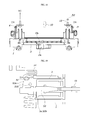
- FIG. 9 is an exemplary diagram illustrating a low beam mode of operation when a beam pattern is implemented, in which FIG. 9 is an exemplary perspective view of a head lamp module when the beam pattern of the low beam mode is implemented;
- FIG. 10 is an exemplary plan view of a shield state viewed from the top when a low beam mode of operation when a beam pattern is implemented according to an exemplary embodiment of the present disclosure
- FIG. 11 is an exemplary cross-sectional view of a portion where the first solenoid is positioned when a low beam mode of operation when a beam pattern is implemented according to an exemplary embodiment of the present disclosure
- FIG. 12 is an exemplary cross-sectional view illustrating a portion where the second solenoid is positioned when a low beam mode of operation when a beam pattern is implemented according to an exemplary embodiment of the present disclosure
- FIG. 13 is an exemplary perspective view of the head lamp module when the beam pattern of the high beam mode is implemented according to an exemplary embodiment of the present disclosure
- FIG. 14 is an exemplary plan view of the shield state viewed from the top, when the beam pattern of the high beam mode is implemented according to an exemplary embodiment of the present disclosure
- FIG. 15 is an exemplary cross-sectional view of the portion where the first solenoid is positioned when the beam pattern of the high beam mode is implemented according to an exemplary embodiment of the present disclosure
- FIG. 16 is an exemplary cross-sectional view illustrating the portion where the second solenoid is positioned when the beam pattern of the high beam mode is implemented according to an exemplary embodiment of the present disclosure
- FIG. 17 is an exemplary perspective view of the head lamp module when the beam pattern of the ADB mode is implemented according to an exemplary embodiment of the present disclosure
- FIG. 18 is an exemplary plan view of the shield state viewed from the top according to an exemplary embodiment of the present disclosure
- FIG. 19 is an exemplary cross-sectional view of the portion where the first solenoid is positioned according to an exemplary embodiment of the present disclosure.
- FIG. 20 is an exemplary cross-sectional view illustrating the portion where the second solenoid is positioned according to an exemplary embodiment of the present disclosure.
- a layer is “on” another layer or substrate, the layer may be directly on another layer or substrate or a third layer may be disposed therebetween.
- control logic of the present disclosure may be embodied as non-transitory computer readable media on a computer readable medium containing executable program instructions executed by a processor, controller/control unit or the like.
- the computer readable mediums include, but are not limited to, ROM, RAM, compact disc (CD)-ROMs, magnetic tapes, floppy disks, flash drives, smart cards and optical data storage devices.
- the computer readable recording medium can also be distributed in network coupled computer systems so that the computer readable media is stored and executed in a distributed fashion, e.g., by a telematics server or a Controller Area Network (CAN).
- a telematics server or a Controller Area Network (CAN).
- CAN Controller Area Network
- vehicle or “vehicular” or other similar term as used herein is inclusive of motor vehicle in general such as passenger automobiles including sports utility vehicles (SUV), buses, trucks, various commercial vehicles, watercraft including a variety of boats, ships, aircraft, and the like and includes hybrid vehicles, electric vehicles, combustion, plug-in hybrid electric vehicles, hydrogen-powered vehicles and other alternative fuel vehicles (e.g. fuels derived from resources other than petroleum).
- motor vehicle in general such as passenger automobiles including sports utility vehicles (SUV), buses, trucks, various commercial vehicles, watercraft including a variety of boats, ships, aircraft, and the like and includes hybrid vehicles, electric vehicles, combustion, plug-in hybrid electric vehicles, hydrogen-powered vehicles and other alternative fuel vehicles (e.g. fuels derived from resources other than petroleum).
- SUV sports utility vehicles
- plug-in hybrid electric vehicles e.g. fuels derived from resources other than petroleum
- the head lamp module for a vehicle may include a shield 2 configured to be axially rotated with respect to a shield housing 1 and have a low beam protrusion 2 a and an ADB protrusion 2 b formed on an exterior circumferential surface thereof.
- a first solenoid 3 and a second solenoid 4 may be each fixedly installed at portions that correspond to both end portions of the shield 2 in the shield housing 1 .
- a first shield operation mechanism 5 and a second shield operation mechanism 6 may be disposed between the first and second solenoids 3 and 4 and may be coupled at both ends of the shield 2 , respectively.
- the shield may be configured to rotate in a first direction when a current is applied to the first and second solenoids 3 and 4 to include a difference in a rotation angle of the shield 2 .
- a first return spring 7 and a second return spring 8 may have both ends each fixed to the first and second shield operation mechanisms 5 and 6 and the shield housing 1 .
- An elastic force may accumulate when the shield 2 is rotated in a first direction and rotate the shield 2 in a second direction using the accumulated elastic force when the current to the first and second solenoids 3 and 4 are terminated to return the shield 2 .
- the head lamp module for a vehicle may further include a PCB 9 coupled to the first and second solenoids 3 and 4 and configured to adjust a supply of current to the first and second solenoids 3 and 4 , a light source 10 coupled to the PCB 9 and configured to be engaged or disengaged (e.g., turned on or off) based on an adjustment of the PCB 9 , a reflector 11 configured to reflect light from the light source 10 in a forward direction and a case 12 with the shield housing 1 and the reflector 11 fixedly installed therein.
- the PCB 9 may be fixedly installed in the shield housing 1 or may be fixedly installed within the case 12 .
- the beam pattern of the low beam mode is implemented.
- the beam pattern of the high beam mode may be implemented.
- the beam pattern of the ADB mode may be implemented.
- the present disclosure may include the shield 2 configured to rotate by operation of the first and second solenoids 3 and 4 and the first and second shield operation mechanisms 5 and 6 and the beam pattern of the low beam mode, the beam pattern of the high beam mode, or the beam pattern of the ADB mode based on the rotation angle of the shield 2 . Accordingly, the manufacturing costs of the head lamp module may be reduced since a stepping motor may be omitted and adjustment of a rotation position of the shield using a separate sensor and complex control logic may be omitted.
- the first shield operation mechanism 5 may include a first crank 51 fixedly coupled to a first end portion of the shield 2 to be rotated with the shield 2 and may include a first end portion of the first return spring 7 fixedly coupled thereto.
- a first plunger 52 may include a first end portion that contacts the first crank 51 and a second end portion that penetrates through the first solenoid 3 .
- the second shield operation mechanism 6 may include a second crank 61 fixedly coupled to a second end portion of the shield 2 to be rotated along with the shield 2 and have a first end portion of the second return spring 8 fixedly coupled thereto and a second plunger 62 configured to have a first end portion contact the second crank 61 and a second end portion penetrate through the second solenoid 4 .
- an operation stroke L 2 of the second plunger 62 may extend a greater distance than an operation stroke L 1 of the first plunger 52 .
- a difference in a rotation angle of the shield 2 may be generated based on the operation of the first and second plungers 52 and 62 .
- the beam pattern of the high beam mode in the beam pattern of the low beam mode may be implemented based on the operation stroke L 1 of the first plunger 52 and the beam pattern of the ADB mode in the beam pattern of the high beam mode based on the operation stroke L 2 of the second plunger 62 .
- the head lamp module for a vehicle may include a stopper 13 coupled to an end portion of a rear of the first plunger 52 that penetrates through the first solenoid 3 and may be configured to adjust a return rotation angle of the shield 2 by contacting a rear surface of the shield housing 1 when the shield 2 is rotated in a second direction to return by a restoring forces of the first return spring 7 and the second return spring 8 .
- the stopper may be coupled to an end portion of a rear of the second plunger 62 penetrating through the second solenoid 4 .
- the first crank 51 and the second crank 61 may be formed from the same shape.
- the first crank 51 may include a pair of first flanges 51 a that protrude in a radial direction and a first rod 51 b disposed between the first flanges 51 .
- a first end portion of the first plunger 52 may include a first protrusion 52 a that contacts the first rod 51 b.
- the first protrusion 51 a may be disposed to contact a circumference of a front side of the first rod 51 b and may be configured to retract the first rod 51 b in a backward direction when the first plunger 51 moves toward the first solenoid 3 to rotate the shield 2 in a first direction.
- the second crank 61 may include a pair of second flanges 61 a that protrude in a radial direction and a second rod 61 b disposed between the second flanges 62 .
- a first end portion of the second plunger 62 may include two second protrusions 62 a that contact the second rod 61 b and may be disposed to insert the second rod 61 b between the two second protrusions 62 a.
- the two second protrusions 62 a may be configured to retract the second rod 61 b in a backward direction when the second plunger 62 moves toward the second solenoid 4 to rotate the shield 2 in a first direction and protrudes forward by the contact with the second rod 61 b when the shield 2 returns while being rotated in a second direction by the second return spring 8 to perform an operation of returning the shield 2 .
- the head lamp module may further include a first damper 14 fixedly installed to the shield housing 1 and contacts the first flange 51 a to reduce noise and a shock when the shield 2 returns by being rotated in a second direction by the restoring forces of the first return spring 7 and the second return spring 8 .
- a second damper 15 may be fixedly installed to the shield housing 1 and contacts the second flange 61 a to reduce noise and a shock when the shield 2 returns by being rotated in a second direction by the restoring force of the second return spring 8 .
- the first and second dampers 14 and 15 may be formed from of any one of rubber, silicon, or synthetic resin having elasticity but are not limited thereto.
- Reference numerals 51 c and 61 c illustrated in FIG. 6 become a contact surface that contact the first and second dampers 14 and 15 in the first and second flanges 51 a and 61 a.
- the operation stroke L 1 of the first plunger 52 may include a distance when a contact surface 51 c of the first flange 51 a contacts the first damper 14 until a first stopper surface 52 b formed at the first plunger 52 contacts a front surface 1 a of the shield housing 1 based on the backward movement of the first plunger 52 toward the first solenoid 3 .
- the operation stroke L 2 of the second plunger 52 may include a distance from when a contact surface 61 c of the second flange 61 a contacts the second damper 15 until a second stopper surface 62 b formed at the second plunger 62 contacts the front surface 1 a of the shield housing 1 based on the backward movement of the second plunger 52 toward the second solenoid 4 and the operation stroke L 2 of the second plunger 62 may be greater than the operation stroke L 1 of the first plunger 52 .
- FIGS. 9 to 12 are exemplary diagrams illustrating a low beam mode state when the beam pattern of the low beam mode is implemented as a low beam protrusion 2 a formed at the shield 2 is positioned in front of the light source 10 .
- FIG. 9 is an exemplary perspective view of the head lamp module when the beam pattern of the low beam mode is implemented.
- FIG. 10 is an exemplary plan view of a shield state viewed from the top.
- FIG. 11 is an exemplary cross-sectional view of a portion where the first solenoid is positioned.
- FIG. 12 is an exemplary cross-sectional view illustrating a portion where the second solenoid is positioned.
- the beam pattern of the low beam mode is implemented at an early state. Therefore, in the low beam state as described above, the supply of current to the first and second solenoids 3 and 4 may be terminated. Accordingly, both of the first and second solenoids 3 and 4 may be turned off.
- the restoring forces of the first and second return springs 7 and 8 may be applied to the first and second cranks 51 and 61 to position the low beam protrusion formed at the shield in front of the light source.
- the first and second flanges 51 a and 61 a may contact the first and second dampers 14 and 15 and the first and second plungers 52 and 62 may be configured to move forward maximally.
- the stopper 13 may maintain contact with the rear surface of the shield housing 1 .
- FIGS. 13 to 16 are exemplary diagrams illustrating a high beam mode when the beam pattern of the high beam mode is implemented as both of the low beam protrusion 2 a and an ADB protrusion 2 b formed at the shield 2 are not positioned in front of the light source 10 .
- FIG. 13 is an exemplary perspective view of the head lamp module when the beam pattern of the high beam mode is implemented.
- FIG. 14 is an exemplary plan view of the shield state viewed from the top.
- FIG. 15 is an exemplary cross-sectional view of the portion where the first solenoid is positioned.
- FIG. 16 is an exemplary cross-sectional view illustrating the portion where the second solenoid is positioned.
- a control to supply (on) a current to the first solenoid 3 and continuously terminate a supply of current to the second solenoid 4 may be performed.
- the first plunger 52 may be configured to move backward (arrow M 1 )
- the first protrusion 52 a may be configured to rotate the first crank 51 in a first direction (e.g., counterclockwise, arrow R 1 ) when the first crank contacts the first rod 51 b.
- the shield 2 may be rotated and therefore both of the low beam protrusion 2 a and the ADB protrusion 2 b may not be positioned in front of the light source 10 , thereby implementing the beam pattern of the high beam mode.
- the first stopper surface 52 b may contact the front surface 1 a of the shield housing 1 to constrain the backward movement of the first plunger 52 .
- the second crank 61 coupled to the second end portion of the shield 2 may be rotated together (e.g., arrow R 2 ).
- a rotating force of the second crank 61 may be transferred to the second protrusion 62 a through the second rod 61 b and thus transferred to the second plunger 62 , to move the second plunger 62 in a backward direction (e.g., arrow M 2 ).
- the second stopper surface 62 b of the second plunger 62 may be spaced apart (e.g., C 1 ) from the front surface 1 a of the shield housing 1 by a predetermined distance and may be configured to continuously move the second plunger 62 in a backward direction when a current is supplied to the second solenoid 4 .
- FIGS. 17 to 20 are exemplary diagrams illustrating an ADB mode state in which the beam pattern of the ADB mode is implemented as the ADB protrusion 2 b formed at the shield 2 is positioned in front of the light source 18 .
- FIG. 17 is an exemplary perspective view of the head lamp module when the beam pattern of the ADB mode is implemented.
- FIG. 18 is an exemplary plan view of the shield state viewed from the top.
- FIG. 19 is an exemplary cross-sectional view of the portion where the first solenoid is positioned.
- FIG. 20 is an exemplary cross-sectional view illustrating the portion where the second solenoid is positioned.
- the second plunger 62 When a current is supplied to the second solenoid 4 , the second plunger 62 may be configured to move backward (e.g., arrow M 3 ) until the second stopper surface 62 b contacts the first surface 1 a of the shield housing 1 .
- the shield 2 When the second stopper surface 62 b contacts the front surface 1 a of the shield housing 1 the backward movement of the second plunger 62 may be terminated and the shield 2 may be configured to rotate in a first direction (e.g., counterclockwise, arrow R 3 ) when the second plunger 62 moves backward.
- the shield 2 may be configured to rotate together and thus the ADB protrusion 2 b may be disposed in front of the light source 10 to implement the beam pattern of the ADB mode.
- the second plunger 62 may be configured to move until the second stopper surface 62 b contacts the front surface 1 a of the shield housing 1 .
- the first plunger 52 may be constrained from backward movement as the first stopper surface 52 b maintains the contact state with the front surface 1 a of the shield housing 1 .
- the shield 2 may be configured to rotate (e.g., arrow R 3 ) in a first direction until the backward movement of the second plunger 62 ends.
- the ADB protrusion 2 b may be disposed in front of the light source 10 and may implement the beam pattern of the ADB mode.
- the supply of current to the first solenoid 3 may be continuously maintained.
- the supply of current to the second solenoid 4 may be terminated and the shield 2 may be configured to be rotated in the opposite direction (e.g., clockwise direction which is an opposite direction to the foregoing counterclockwise direction, the second direction) by the restoring forces of the first return spring 7 .
- the second return spring 8 and the second plunger 62 may be configured to move in a forward direction by the rotation of the shield 2 .
- the beam pattern of the high beam mode may be implemented.
- the supply of current to the second solenoid 4 may be maintained on the contrary to the foregoing description upon the returning from the high beam mode to the low beam mode.
- the supply of current to the first solenoid may be terminated and the shield 2 may be configured to be rotated in a second direction (e.g., clockwise) by the restoring force of the first return spring 7 and the first and second plungers 52 and 62 and may be configured to move in a forward direction by the rotation of the shield 2 to return to the initial position.
- the first and second cranks 51 and 52 contact the first and second dampers 14 and 15 and the stopper 13 contacts the rear surface of the shield housing 1 the return action of the first plunger 52 and the return rotation angle of the shield 2 may be constrained.
- the low beam protrusion 2 a is positioned in front of the light source 10 the beam pattern of the low beam mode may be implemented.
- the shield 2 may be rotated by the operations of the first and second solenoids 3 and 4 and the first and second shield operation mechanisms 5 and 6 and the beam pattern of the low beam mode, the beam pattern of the high beam mode, or the beam pattern of the ADB mode may be implemented based on the rotation angle of the shield 2 . Accordingly the manufacturing costs of the head lamp module may be reduced and may provide an alternative to operation of the shield using the expensive stepping motor and implement the beam pattern based thereon. In particular, the rotation position of the shield may be adjusted using the separate sensor.
- the complex control logic may be included based on the use of the stepping motor and the head lamp module may be applied.
- the fail safe function may be performed.
- the supply of current to the second and first solenoids 4 and 3 in the high beam mode or the ADB mode as described above may be sequentially terminated
- the beam pattern of the high beam mode or the beam pattern of the ADB mode may be adjusted to the beam pattern of the low beam mode. Accordingly, the driver may secure the sufficient visual range through the beam pattern of the low beam mode even though the emergency situation occurs, thereby increasing the driving safety of the vehicle.
- the shield may be configured to be rotated by operations of the first and second solenoids and the first and second shield operation mechanisms and the beam pattern of the low beam mode, the beam pattern of the high beam mode, or the beam pattern of the ADB mode may be implemented based on the rotation angle of the shield. Accordingly the manufacturing costs of the head lamp module may be reduced in comparison with the manufacturing costs of the existing head lamp module of operating the shield that require use of the expensive stepping motor to implement the beam pattern. Further, the beam pattern of the low beam mode may be implemented when the fail safe function may be performed based on the failure occurrence in the high beam mode condition or the ADB mode condition. Accordingly, the driver may secure the sufficient visual range even during an emergency situation, thereby promoting the driving safety
Landscapes
- Engineering & Computer Science (AREA)
- General Engineering & Computer Science (AREA)
- Mechanical Engineering (AREA)
- Non-Portable Lighting Devices Or Systems Thereof (AREA)
- Lighting Device Outwards From Vehicle And Optical Signal (AREA)
Abstract
Description
Claims (10)
Applications Claiming Priority (2)
| Application Number | Priority Date | Filing Date | Title |
|---|---|---|---|
| KR10-2016-0042365 | 2016-04-06 | ||
| KR1020160042365A KR101766133B1 (en) | 2016-04-06 | 2016-04-06 | Head lamp module for vehicle |
Publications (2)
| Publication Number | Publication Date |
|---|---|
| US20170291530A1 US20170291530A1 (en) | 2017-10-12 |
| US9873370B2 true US9873370B2 (en) | 2018-01-23 |
Family
ID=59653248
Family Applications (1)
| Application Number | Title | Priority Date | Filing Date |
|---|---|---|---|
| US15/237,968 Active US9873370B2 (en) | 2016-04-06 | 2016-08-16 | Head lamp module for vehicle |
Country Status (3)
| Country | Link |
|---|---|
| US (1) | US9873370B2 (en) |
| KR (1) | KR101766133B1 (en) |
| CN (1) | CN107270208B (en) |
Families Citing this family (4)
| Publication number | Priority date | Publication date | Assignee | Title |
|---|---|---|---|---|
| KR20250070907A (en) | 2023-11-14 | 2025-05-21 | 에스엘 주식회사 | A lamp for vehicle and a manufacturing method thereof and a manufacturing apparatus thereof |
| KR20250098160A (en) | 2023-12-22 | 2025-07-01 | 에스엘 주식회사 | A flush door handle for a vehicle |
| CN120231459A (en) | 2023-12-28 | 2025-07-01 | Sl株式会社 | Vehicle swing door handle |
| KR20260000488U (en) | 2024-10-07 | 2026-04-14 | 에스엘 주식회사 | A lamp for vehicle |
Citations (9)
| Publication number | Priority date | Publication date | Assignee | Title |
|---|---|---|---|---|
| US1631130A (en) * | 1924-04-28 | 1927-06-07 | Hoefler Carl Perry | Shield for automobile headlights |
| JP2001110213A (en) | 1999-10-05 | 2001-04-20 | Koito Mfg Co Ltd | Vehicle headlights |
| JP2002056708A (en) | 2000-08-07 | 2002-02-22 | Ichikoh Ind Ltd | Vehicle headlamp device |
| KR20030005781A (en) | 2001-07-10 | 2003-01-23 | 주식회사 성산 | a beam conversion device of headlight for an automobile |
| US6948837B2 (en) * | 2003-03-07 | 2005-09-27 | Ichikoh Industries, Ltd. | Pattern-variable headlamp |
| JP2006164686A (en) | 2004-12-06 | 2006-06-22 | Ichikoh Ind Ltd | head lamp |
| US20100002457A1 (en) * | 2008-07-03 | 2010-01-07 | Koito Manufacturing Co., Ltd. | Vehicle headlamp |
| JP2011100662A (en) | 2009-11-06 | 2011-05-19 | Koito Mfg Co Ltd | Vehicle headlight device |
| KR20120050271A (en) | 2010-11-10 | 2012-05-18 | 기아자동차주식회사 | Projection head lamp assembly for vehicle |
Family Cites Families (2)
| Publication number | Priority date | Publication date | Assignee | Title |
|---|---|---|---|---|
| KR20100025253A (en) * | 2008-08-27 | 2010-03-09 | 에스엘 주식회사 | Lamp shield driving apparatus and lamp assembly including the same |
| JP2014072139A (en) * | 2012-10-01 | 2014-04-21 | Koito Mfg Co Ltd | Vehicle head lamp |
-
2016
- 2016-04-06 KR KR1020160042365A patent/KR101766133B1/en active Active
- 2016-08-16 US US15/237,968 patent/US9873370B2/en active Active
- 2016-09-14 CN CN201610827285.5A patent/CN107270208B/en active Active
Patent Citations (10)
| Publication number | Priority date | Publication date | Assignee | Title |
|---|---|---|---|---|
| US1631130A (en) * | 1924-04-28 | 1927-06-07 | Hoefler Carl Perry | Shield for automobile headlights |
| JP2001110213A (en) | 1999-10-05 | 2001-04-20 | Koito Mfg Co Ltd | Vehicle headlights |
| JP2002056708A (en) | 2000-08-07 | 2002-02-22 | Ichikoh Ind Ltd | Vehicle headlamp device |
| KR20030005781A (en) | 2001-07-10 | 2003-01-23 | 주식회사 성산 | a beam conversion device of headlight for an automobile |
| US6948837B2 (en) * | 2003-03-07 | 2005-09-27 | Ichikoh Industries, Ltd. | Pattern-variable headlamp |
| JP2006164686A (en) | 2004-12-06 | 2006-06-22 | Ichikoh Ind Ltd | head lamp |
| US20100002457A1 (en) * | 2008-07-03 | 2010-01-07 | Koito Manufacturing Co., Ltd. | Vehicle headlamp |
| US8104938B2 (en) * | 2008-07-03 | 2012-01-31 | Koito Manufacturing Co., Ltd | Vehicle headlamp |
| JP2011100662A (en) | 2009-11-06 | 2011-05-19 | Koito Mfg Co Ltd | Vehicle headlight device |
| KR20120050271A (en) | 2010-11-10 | 2012-05-18 | 기아자동차주식회사 | Projection head lamp assembly for vehicle |
Also Published As
| Publication number | Publication date |
|---|---|
| US20170291530A1 (en) | 2017-10-12 |
| CN107270208A (en) | 2017-10-20 |
| KR101766133B1 (en) | 2017-08-08 |
| CN107270208B (en) | 2021-02-19 |
Similar Documents
| Publication | Publication Date | Title |
|---|---|---|
| US9873370B2 (en) | Head lamp module for vehicle | |
| US9931977B2 (en) | Vehicle lamp | |
| EP2543542B1 (en) | Automotive turn signal lamp and controlling method for the same | |
| US9879839B2 (en) | Lamp apparatus for vehicle | |
| US9937856B2 (en) | Automotive lamp and controlling method for the same | |
| US9783096B2 (en) | Automotive lamp and method of controlling the same | |
| US9789807B2 (en) | Lamp for vehicle and controlling method thereof | |
| US8874312B2 (en) | Automotive headlamp control apparatus and method | |
| US7926992B2 (en) | Lamp shield driving device and headlamp assembly including the same | |
| US11914032B2 (en) | Radar support device | |
| CN106482059B (en) | Automobile headlight module | |
| US20190113203A1 (en) | Rear lamp apparatus of vehicle | |
| US11630477B2 (en) | Foldable pedal apparatus for vehicle | |
| CN109895690B (en) | Structure for fixing skylight lighting module | |
| US11498477B2 (en) | Rotation center decoupling type aiming lamp and vehicle including the aiming lamp | |
| EP2597364B1 (en) | Apparatus and method for controlling a vehicle headlamp | |
| CN106958781B (en) | Guard drives for headlights | |
| US11889628B2 (en) | Electronic control device | |
| US10513250B2 (en) | Method and apparatus for preventing parking malfunction during remote start-up | |
| US20190072254A1 (en) | Rear lamp apparatus of vehicle | |
| US20200292060A1 (en) | Hydraulic type scissors gear of vehicle engine | |
| KR20170009334A (en) | Lighting apparatus for an automobile | |
| KR19990056696A (en) | Auto mirror |
Legal Events
| Date | Code | Title | Description |
|---|---|---|---|
| AS | Assignment |
Owner name: HYUNDAI MOTOR COMPANY, KOREA, REPUBLIC OF Free format text: ASSIGNMENT OF ASSIGNORS INTEREST;ASSIGNORS:SHIN, JIK SOO;AHN, BYOUNG SUK;LEE, KI HONG;AND OTHERS;REEL/FRAME:039454/0378 Effective date: 20160725 Owner name: HYUNDAI MOBIS CO., LTD., KOREA, REPUBLIC OF Free format text: ASSIGNMENT OF ASSIGNORS INTEREST;ASSIGNORS:SHIN, JIK SOO;AHN, BYOUNG SUK;LEE, KI HONG;AND OTHERS;REEL/FRAME:039454/0378 Effective date: 20160725 |
|
| STCF | Information on status: patent grant |
Free format text: PATENTED CASE |
|
| MAFP | Maintenance fee payment |
Free format text: PAYMENT OF MAINTENANCE FEE, 4TH YEAR, LARGE ENTITY (ORIGINAL EVENT CODE: M1551); ENTITY STATUS OF PATENT OWNER: LARGE ENTITY Year of fee payment: 4 |
|
| MAFP | Maintenance fee payment |
Free format text: PAYMENT OF MAINTENANCE FEE, 8TH YEAR, LARGE ENTITY (ORIGINAL EVENT CODE: M1552); ENTITY STATUS OF PATENT OWNER: LARGE ENTITY Year of fee payment: 8 |