US9871940B2 - Information processing system, information processing apparatus, and method for processing information - Google Patents
Information processing system, information processing apparatus, and method for processing information Download PDFInfo
- Publication number
- US9871940B2 US9871940B2 US15/232,945 US201615232945A US9871940B2 US 9871940 B2 US9871940 B2 US 9871940B2 US 201615232945 A US201615232945 A US 201615232945A US 9871940 B2 US9871940 B2 US 9871940B2
- Authority
- US
- United States
- Prior art keywords
- flow
- identification information
- processes
- program
- sequence
- Prior art date
- Legal status (The legal status is an assumption and is not a legal conclusion. Google has not performed a legal analysis and makes no representation as to the accuracy of the status listed.)
- Expired - Fee Related
Links
Images


Classifications
-
- H—ELECTRICITY
- H04—ELECTRIC COMMUNICATION TECHNIQUE
- H04N—PICTORIAL COMMUNICATION, e.g. TELEVISION
- H04N1/00—Scanning, transmission or reproduction of documents or the like, e.g. facsimile transmission; Details thereof
- H04N1/00912—Arrangements for controlling a still picture apparatus or components thereof not otherwise provided for
- H04N1/00938—Software related arrangements, e.g. loading applications
- H04N1/00949—Combining applications, e.g. to create workflows
-
- H—ELECTRICITY
- H04—ELECTRIC COMMUNICATION TECHNIQUE
- H04N—PICTORIAL COMMUNICATION, e.g. TELEVISION
- H04N1/00—Scanning, transmission or reproduction of documents or the like, e.g. facsimile transmission; Details thereof
- H04N1/00002—Diagnosis, testing or measuring; Detecting, analysing or monitoring not otherwise provided for
- H04N1/00026—Methods therefor
- H04N1/00042—Monitoring, i.e. observation
-
- H—ELECTRICITY
- H04—ELECTRIC COMMUNICATION TECHNIQUE
- H04N—PICTORIAL COMMUNICATION, e.g. TELEVISION
- H04N1/00—Scanning, transmission or reproduction of documents or the like, e.g. facsimile transmission; Details thereof
- H04N1/00127—Connection or combination of a still picture apparatus with another apparatus, e.g. for storage, processing or transmission of still picture signals or of information associated with a still picture
- H04N1/00344—Connection or combination of a still picture apparatus with another apparatus, e.g. for storage, processing or transmission of still picture signals or of information associated with a still picture with a management, maintenance, service or repair apparatus
-
- H—ELECTRICITY
- H04—ELECTRIC COMMUNICATION TECHNIQUE
- H04N—PICTORIAL COMMUNICATION, e.g. TELEVISION
- H04N2201/00—Indexing scheme relating to scanning, transmission or reproduction of documents or the like, and to details thereof
- H04N2201/0077—Types of the still picture apparatus
- H04N2201/0094—Multifunctional device, i.e. a device capable of all of reading, reproducing, copying, facsimile transception, file transception
Definitions
- the present disclosure relates to information devices, and in particular, relates to an information device that utilizes a touch screen.
- the present invention relates to an information processing system, an information processing apparatus, and a method for processing information.
- a technique of generating a clerical flow for controlling component parts performing various processes based on a predetermined clerical flow model for example, Japanese Patent No. 5112085.
- the component parts are combined by the generated clerical flow, and sequential processes implementing a clerical process are performed.
- an information processing system including at least one information processing apparatus and also including at least one program respectively executing predetermined processes
- the information processing system including a hardware processor and a hardware storage
- the hardware storage is configured to implement a first memory unit storing, for each application executing a sequence of processes using electronic data, flow information which defines program identification information for identifying the at least one program executing each process of the sequence of processes and an execution order of the at least one program, app identification information identifying app identification information, and flow identification information identifying flow identification information while associating the flow information, the app identification information, and flow identification information; and a second memory unit storing first flow identification information identifying first flow information which defines the program identification information for identifying the at least one program executing each process of a first sequence of processes and an execution order of the at least one program, program identification information identifying the at least one program executing each process of a second sequence of processes, which is executed in response to an error that occurs in the first sequence of processes, and second flow identification information
- FIG. 1 is a diagram illustrating a system structure of an exemplary information processing system of a first embodiment
- FIG. 2 is a diagram illustrating a hardware structure of an exemplary service providing system of the first embodiment
- FIG. 3 is a diagram illustrating a hardware structure of an exemplary image forming apparatus of the first embodiment
- FIG. 4 is a processing block diagram illustrating an exemplary information processing system of the first embodiment
- FIGS. 5A to 5D illustrate an exemplary common interface (I/F) and an exemplary unique I/F;
- FIGS. 6A and 6B illustrate an exemplary process content of the first embodiment
- FIG. 7 is a processing block diagram of an exemplary logic processing unit of the first embodiment
- FIG. 8 illustrates an exemplary substitute-flow administering table of the first embodiment
- FIG. 9 is a sequence diagram of an exemplary overall process of a scan delivery service of the first embodiment.
- FIG. 10 illustrates an exemplary application screen for using a scan delivery service
- FIG. 11 is a sequence chart of an exemplary flow execution process of the first embodiment
- FIG. 12 is a sequence chart of another exemplary flow execution process of the first embodiment
- FIG. 13 is a processing block diagram of an exemplary logic processing unit of a second embodiment
- FIG. 14 illustrates an exemplary substitute-flow administering table of the second embodiment
- FIG. 15 is a sequence chart of an exemplary flow execution process of the second embodiment
- FIG. 16 is a processing block diagram of an exemplary logic processing unit of a third embodiment
- FIG. 17 illustrates an exemplary substitute-flow administering table of the third embodiment
- FIG. 18 is a sequence chart of an exemplary flow execution process of the third embodiment.
- FIG. 19 is a processing block diagram of an exemplary logic processing unit of a fourth embodiment
- FIG. 20 illustrates an exemplary substitute-component administering table of the fourth embodiment
- FIG. 21 is a sequence chart of an exemplary flow execution process of the fourth embodiment.
- FIG. 22 illustrates an exemplary process content of the fourth embodiment
- FIG. 23 is a processing block diagram of an exemplary logic processing unit of a fifth embodiment
- FIG. 24 illustrates an exemplary substitute-component administering table of the fifth embodiment
- FIG. 25 is a sequence chart of an exemplary flow execution process of the fifth embodiment.
- FIG. 26 illustrates an exemplary process content of the fifth embodiment
- FIG. 27 is a processing block diagram of an exemplary logic processing unit of a sixth embodiment
- FIG. 28 illustrates an exemplary substitute-component administering table of the sixth embodiment
- FIG. 29 is a sequence chart of an exemplary flow execution process of the sixth embodiment.
- FIG. 30 illustrates an exemplary process content of a sixth embodiment.
- FIG. 1 is a diagram illustrating a system structure of an exemplary information processing system of the first embodiment.
- the information processing system 1 illustrated in FIG. 1 includes a service providing environment E 1 , a user environment E 2 , and an external storage system 30 , and is communicably coupled through a wide area network N 1 such as the Internet.
- the service providing environment E 1 is a system environment which provides an external service such as a cloud service through the network N 1 .
- the cloud service is adopted for description as a specific example of the external service.
- the first embodiment can be applied to a service provided through the network such as a service provided by an application service provider (ASP), a web service, and so on.
- ASP application service provider
- the service providing environment E 1 includes a service providing system 10 implemented by at least one information processing apparatus.
- the service providing system 10 provides a predetermined service through the network N 1 .
- the service providing system 10 provides a service (a scan delivery service), in which an electronic file generated by scanning an original in the image forming apparatus 20 of the user environment E 2 is subjected to an optical character reader (OCR) process, is subjected to a translating process of language, and is stored in the external storage system 30 .
- a service a scan delivery service
- OCR optical character reader
- a service provided by the service providing system 10 is not limited to the scan delivery service. Further, for example, the service providing system 10 may provide a service of printing the electronic file, which is stored in the external storage system 30 , using the image forming apparatus 20 of the user environment E 2 . Further, for example, the service providing system 10 may provides a service of projecting the electronic file, which is stored in the external storage system 30 , using a scanner of the user environment E 2 .
- All or a part of the service providing system 10 may be installed in the user environment E 2 . Said differently, all or a part of the information processing apparatus forming the service providing system 10 may be included in the user environment E 2 .
- the user environment E 2 is, for example, a system environment in a company such as a user using the image forming apparatus 20 .
- a network such as a local area network (LAN) or the like.
- the image forming apparatus 20 of the first embodiment is a multifunction peripheral (MFP) having a scan function.
- the image forming apparatus 20 may have a print function, a copy function, a facsimile (fax) communication function, or the like in addition to the scan function.
- the external storage system 30 is a computer system providing a cloud service called a storage service or an online storage through the network N 1 .
- the storage service is a service of lending a memory area of a storage of the external storage system 30 .
- the electronic file undergoing the OCR process and the translating process is stored (uploaded) in the memory area lent by the external storage system 30 .
- each of multiple external storage systems 30 is distinguished, it is referred to as an “external storage system 301 ”, an “external storage system 302 ”, or the like.
- the name of the service provided by the external storage system 301 is referred to as a “storage service A”
- the service name provided by the external storage system 302 is referred to as a “storage service B”.
- the external storage system 30 may be a system formed by multiple information processing apparatuses.
- the structure of the information processing system 1 illustrated in FIG. 1 is an example and may be another structure.
- the user environment E 2 may include various apparatuses such as a projector and an electronic blackboard in addition to or in place of the image forming apparatus 20 .
- FIG. 2 is a diagram illustrating a hardware structure of an exemplary service providing system of the first embodiment.
- the service providing system 10 illustrated in FIG. 2 includes an input device 11 , a display device 12 , an external interface (I/F), and a random access memory (RAM) 14 . Further, the service providing system 10 includes a read only memory (ROM) 15 , a central processing unit (CPU) 16 , a communication I/F 17 , and a hard disk drive (HDD) 18 . These hardware apparatuses are coupled by a bus B.
- ROM read only memory
- CPU central processing unit
- HDD hard disk drive
- the input device 11 includes a keyboard, a mouse, a touch panel, and the like, by which a user input various operation signals.
- the display device 12 includes a display or the like to display a processed result acquired by the service providing system 10 . It is acceptable to provide a structure such that the input device 11 and the display device 12 may be coupled to the bus B when preferred so.
- the communication I/F 17 is an interface provided to couple the service providing system 10 with the network N 1 .
- the service providing system 10 can perform data communications with another apparatus through the communication I/F 17 .
- the HDD 18 is a non-volatile memory device that stores programs and data.
- the stored program and data are an operating system (OS), which is basic software controlling the entire service providing system 10 , application software providing various functions in the OS, and so on.
- OS operating system
- the service providing system 10 may use a drive device using a flash memory (e.g., a solid state drive (SSD)) as a memory medium in place of the HDD 108 . Further, the HDD 108 administers the stored program and the stored data using at least one of a predetermined file system and a predetermined database (DB).
- a flash memory e.g., a solid state drive (SSD)
- DB predetermined database
- the external I/F 13 is an interface with an external apparatus.
- the external apparatus includes a recording medium 13 a and so on. With this, the service providing system 10 can read information from the recording medium 13 a or write the information to the recording medium 13 a through the external I/F 13 .
- the recording medium 13 a is a flexible disk, a CD, a DVD, an SD memory card, a USB memory, or the like.
- the ROM 15 is a non-volatile semiconductor memory (a memory device), which can hold a program and data even when a power source is powered off.
- the ROM 15 stores a program and data such as a basic input/output system (BIOS), an operating system (OS) setup, a network setup, or the like, which are executed at a time of starting up the service providing system 10 .
- the RAM 14 is a volatile semiconductor memory temporarily storing the program or the data.
- the CPU 16 reads the program or the data from the ROM 15 , the HDD 18 , or the like.
- the read program or the read data undergo a process to implement an overall control or a function of the entire service providing system 10 .
- the service providing system 10 of the first embodiment can implement various processes described below using the above hardware structure of the service providing system 10 .
- FIG. 3 is a diagram illustrating a hardware structure of an exemplary image forming apparatus of the first embodiment.
- the image forming apparatus 20 illustrated in FIG. 3 includes a controller 21 , an operation panel 22 , an external I/F 23 , a communication I/F 24 , and a scanner 606 .
- the controller 21 includes a CPU 211 , a RAM 212 , a ROM 213 , an NVRAM 214 , and an HDD 215 .
- the RAM 212 temporarily stores the program and the data.
- Setup information or the like is stored in the NVRAM 214 .
- Various programs and data are stored in the ROM 215 .
- the CPU 211 reads the program, the data, setup information, or the like into the RAM 212 from the ROM 213 , the NVRAM 214 , the HDD 215 , or the like, and performs the process. Thus, the CPU 211 substantializes an entire control or functions of the image forming apparatus 20 .
- the operation panel 22 includes an input unit for receiving an input from the user and a display unit for a display.
- the external I/F 23 is an interface with an external apparatus.
- the external apparatus includes a recording medium 23 a and so on. With this, the image forming apparatus 20 can read information from the recording medium 23 a or write the information to the recording medium 23 a through the external I/F 23 .
- the recording medium 23 a is an IC card, a flexible disk, a CD, a DVD, an SD memory card, a USB memory, or the like.
- the communication I/F 24 is an interface provided to couple the image forming apparatus 20 with the network N 1 .
- the image forming apparatus 20 can perform data communications with another apparatus through the communication I/F 24 .
- the scanner 25 is a reading apparatus which reads the original and generates an image file (an electronic file).
- the image forming apparatus 20 of the first embodiment can perform various processes described below with the above hardware structure.
- FIG. 4 is a processing block diagram illustrating an exemplary information processing system of the first embodiment.
- the image forming apparatus 20 includes a browser 210 implemented by, for example, the CPU 211 .
- the user of the image forming apparatus 20 can use a service provided by the service providing system 10 through the browser 210 .
- the browser 210 may be installed on the image forming apparatus 20 .
- a dedicated application which is to be used by the image forming apparatus 20 , is not developed.
- the service providing system 10 illustrated in FIG. 4 includes a service processing unit 110 , a document servicing unit 150 , and a storage-service collaborating unit 160 . These units are implemented when one or more programs installed on the service providing system 10 are executed by the CPU 16 .
- the service providing system 10 includes an application information memory unit 190 .
- the application (app) information memory unit 190 can be implemented by the HDD 18 .
- the app information memory unit 190 can be implemented by a memory device or the like coupled to the service providing system 10 through the network.
- the service processing unit 110 performs a process related to various services in response to a request from the browser 210 of the image forming apparatus 20 .
- the service processing unit 110 includes an app administering unit 120 , a logic processing unit 130 , and a data I/F unit 140 .
- An application (app) administering unit 120 administers application information 1000 stored in an app information memory unit 190 .
- the app administering unit 120 returns an app screen formed based on a screen definition included in the app information 1000 in response to a request from the browser 210 .
- the app screen for using a service provided by the service providing system 10 is displayed on the operation panel 22 by the browser 210 of the image forming apparatus 20 .
- the app information 1000 includes screen definition for causing the image forming apparatus 20 to display the app screen and a process content for substantializing a service used from the app screen.
- the app information 1000 may include multiple screen definitions and multiple process contents.
- the application administering unit 120 returns the process content included in the app information 1000 in response to a request from the logic process unit 130 .
- the process content describes a sequence of processes (hereinafter, referred to as a “process flow” for sustantializing the service provided by the service providing system 10 .
- the logic processing unit 130 acquires the process content from the app administering unit 120 in response to a request received from the browser 210 .
- the logic processing unit 130 executes the sequence of processes based on the acquired process content.
- the logic processing unit 130 requests at least one of the document servicing unit 150 and the file processing unit 170 of the storage-service collaborating unit 160 to execute the process in conformity with the process content, and the sequence of processes are executed based on the process content.
- the service providing system 10 of the first embodiment can provides various services to the image forming apparatus. A detailed processing block of the logic processing unit 130 is described later.
- the data I/F unit 140 sends a predetermined request (for example, a request to acquire a folder view) to a data processing unit 180 of the storage-service collaborating unit 160 in response to a request received from the browser 210 .
- a predetermined request for example, a request to acquire a folder view
- the document servicing unit 150 is a program (module) group substantializing a service provided by the service providing system 10 .
- the document servicing unit 150 includes a program for an optical character reader (OCR) process 151 of performing an OCR process to an electronic file and a program for a translating process 152 of translating a document file (an electronic file) described in a predetermined language to another predetermined language.
- OCR optical character reader
- the document servicing unit 150 may include various programs in addition to or in place of the above programs.
- the document servicing unit 150 may include a program of converting the electronic file to have a data format (print data) which can be printed by the image forming apparatus 20 and a program of compressing or decompressing the electronic file.
- a program of converting the electronic file to have a data format (print data) which can be printed by the image forming apparatus 20 and a program of compressing or decompressing the electronic file.
- the storage-service collaborating unit 160 requests the external storage system 30 to execute various processes in response to a request received from the logic processing unit 130 or the data I/F unit 140 .
- the service providing system 10 includes the storage-service collaborating units 160 respectively for the external storage systems 30 .
- the service providing system 10 includes a storage-service A collaborating unit 1601 for requesting an external storage system 301 to process and a storage-service B collaborating unit 1602 for requesting an external storage system 302 to process.
- the service providing system 10 includes the storage-service collaborating units 160 , which respectively correspond to the external storage systems 30 processing in collaboration with the service providing system 10 .
- the multiple storage-service collaborating units 160 are individually distinguished by a “storage-service A collaborating unit 1601 ”, a “storage-service B collaborating unit 1602 ”, and so on when preferred so.
- the storage-service collaborating unit 160 includes the file processing unit 170 of receiving the request from the logic processing unit 130 and the data processing unit 180 of receiving the request from the data I/F unit 140 .
- the file processing unit 170 includes a common I/F 171 and a unique I/F 172 , in which an application programming interface (API) for conducting an operation (e.g., an acquisition, a storage, and an edit) to the electronic file stored in the external storage system 30 is defined.
- API application programming interface
- the common I/F 171 is an API used among the multiple external storage systems in common as, for example, the API illustrated in FIG. 5A .
- the common I/Fs 171 of the file processing units 170 are API groups for using a function (e.g., a file acquisition, a file storage, or the like) related to a file operation and can be used by all the external storage systems 30 .
- the unique I/F 172 is an API used by a specific external storage system 30 as, for example, the API illustrated in FIG. 5B .
- the unique I/F 172 of the file processing unit 170 is an API group for using a function (e.g., a file edit or the like) related to the file operation and can be used by a specific external storage system 30 .
- the common I/Fs 171 are similarly defined with respect to all the storage-service collaborating units 160 .
- the unique I/F 172 is individually defined with respect to the specific storage-service collaborating unit 160 , in which the API defined by the unique I/F 172 can be used.
- the data processing unit 180 includes a common I/F 181 and a unique I/F 182 , in which an API for acquiring meta data (e.g., an file view, a folder view, or the like) of bibliographic information of the electronic file stored in the external storage system 30 is defined.
- meta data e.g., an file view, a folder view, or the like
- the common I/Fs 181 are APIs used among the multiple external storage systems 30 in common as, for example, the API illustrated in FIG. 5C . Said differently, the common I/Fs 181 of the data processing units 180 is API groups for using a function of a meta data acquisition, which can be used by all the external storage systems 30 .
- the unique I/F 182 is an API used by a specific external storage system 30 as, for example, the API illustrated in FIG. 5D .
- the unique I/F 182 of the data processing unit 180 is an API group for using a function of metadata acquisition (e.g., acquisition of an image file view), which can be used by a specific external storage system 30 .
- the common I/Fs 181 are similarly defined with respect to all the storage-service collaborating units 160 .
- the unique I/F 182 is individually defined with respect to the specific storage-service collaborating unit 160 , in which the API defined by the unique I/F 182 can be used.
- the service providing system 10 includes the storage-service collaborating units 160 respectively corresponding to the external storage systems 30 , which respectively process in collaboration with the storage-service collaborating unit 160 . Therefore, in a case where the external storage system 30 to be a collaboration destination is added, the storage-service collaborating unit 160 corresponding to the external storage system 30 may be added to the service providing system 10 .
- an influence caused by adding the external storage system 30 to be the collaboration destination can be localized. Said differently, without influencing another processing block (the service processing unit 110 , the document servicing unit 150 , or the like)(without a need of modifying the other processing block), the external storage system 30 to be the collaboration destination can be added.
- SDK software development kit
- the common I/F 171 and the unique I/F 172 are respectively implemented by different modules.
- the API defined by the common I/F and the unique I/F can be used by designating a “storage service name” (an external service name). Said differently, the “storage service name” (the external service name) is a variable portion in the common I/F and the unique I/F.
- the external storage system 30 to be the collaboration destination it is possible to reuse the common I/F 171 defined in another storage-service collaborating unit 160 .
- the unique I/F 172 of the external storage system 30 to be added may be developed. Therefore, in the service providing system 10 of the first embodiment, the man-hour for the development caused by adding the external storage system 30 to be the collaboration destination can be further reduced.
- the above merits in the common I/F 171 and the unique I/F 172 are similarly applicable to the common I/F and the unique I/F 182 of the data processing unit 180 .
- the app information memory unit 190 stores app information 1000 .
- the app information 1000 includes a screen definition causing the image forming apparatus 20 to display the app screen and a process content describing a content of a sequence of processes substantializing a service, which is used from the app screen.
- An app ID for uniquely identifying the app information 1000 is given to the app information 1000 .
- the app ID of the app information 1000 for providing the scan delivery service of the first embodiment is “app 001 ”. Further, the app information 1000 of the app ID “app 001 ” includes process content 1100 for substantializing the scan delivery service in collaboration with the storage service A and process content 1200 for substantializing the scan delivery service in collaboration with the storage service B.
- FIGS. 6A and 6B illustrate exemplary process contents of the first embodiment.
- the process content 1100 illustrated in FIG. 6A includes a flow ID definition part 1101 and a process definition part 1102 .
- a flow ID definition part 1101 an app ID “app 001 ” and a flow ID “flow 001 ”, which uniquely identify the process content 1100 , are described.
- the process definition part 1102 describes a content of a sequence of processes for substantializing the scan delivery service in collaboration with the storage service A. Said differently, the process content 1100 illustrated in FIG. 6A describes the sequence of processes of providing the OCR process to the electronic file generated by scanning, thereafter providing the translating process to the above, and storing the translation in the external storage system 301 .
- the process content 1200 illustrated in FIG. 6B includes a flow ID definition part 1201 and a process definition part 1202 .
- a flow ID “flow 002 ” uniquely identifying the process content 1200 is described.
- the process definition part 1202 describes a content of a sequence of processes for substantializing the scan delivery service in collaboration with the storage service B. Said differently, the process content 1200 illustrated in FIG. 6B describes the sequence of processes of providing the OCR process to the electronic file generated by scanning, thereafter providing the translating process to the above, and storing the translation in the external storage system 302 .
- the execution order of the processes defined in the process content 1100 illustrated in FIG. 6A and the process content 1200 illustrated in FIG. 6B is a sequence from up to down. Said differently, in the process content 1100 illustrated in FIG. 6A , the content of the processes described in the process definition part 1102 is performed beginning at the top. In a manner similar to the above, the process content 1200 illustrated in FIG. 6 B, the content of the processes described in the process definition part 1202 is performed beginning at the top.
- the first embodiment is not limited thereto.
- the process content 1100 and the process content 1200 may define information indicative of the execution order of the processes included in the sequence of processes.
- the service providing system 10 of the first embodiment includes the app information 1000 , including the screen definition for causing the image forming apparatus 20 to display the app screen and the process content describing the content of the sequence of processes (a process flow) for substantializing the service.
- the service providing system 10 of the first embodiment can provides various services to the image forming apparatus 20 . Therefore, in a case where a service provided by the service providing system 10 is added, the application information 1000 may be added to the app information memory unit 190 .
- the screen definition and the process content may be described in order to add the app information 1000 . Therefore, the development becomes easy. Therefore, a man-hour caused by an addition or a change of the service can be reduced, and the addition or the change of the service by, for example, a third vendor or the like can be easily conducted.
- FIG. 7 is a processing block diagram of an exemplary logic processing unit of the first embodiment.
- the logic processing unit 130 includes a flow executing unit 131 , a component administering unit 132 , and a component group 133 .
- the logic processing unit 130 uses a substitute-flow administering table 2000 .
- the flow executing unit 131 In receipt of a flow execution request to execute a flow for substantializing the service from a browser 210 , the flow executing unit 131 acquires the process content corresponding to a flow identification (ID) included in the flow execution request through the app administering unit 120 . Then, the flow executing unit 131 requests a component to execute the process in accordance with the acquired process content.
- the component is a module or the like for executing one process from among the sequence of processes based on the process content, and is defined by, for example, a class, a function, or the like.
- the flow executing unit 131 acquires a substitute flow ID from the substitute-flow administering table 2000 .
- the flow executing unit 131 acquires the process content corresponding to the substitute flow ID through the app administering unit 120 to request the component to execute the process in accordance with the process content.
- the substitute flow ID is a flow ID of the process content (a substitute flow content) executed in a case where the error or the like occurs in the sequence of processes (the process flow) based on a certain process content.
- the substitute flow content describes the content of the process for acquiring a processed result similar to the processed result in the process flow.
- the flow executing unit 131 executes the sequence of processes (a substitute flow) based on the substitute flow content of the substitute flow ID associated with the flow ID of the process flow in the substitute-flow administering table 2000 .
- the component administering unit 132 generates the component in response to the request from the flow executing unit 131 .
- the generation of the component means that the component defined by, for example, the class is deployed on the memory (for example, the RAM 14 ).
- the component group 133 is a set of the components.
- the component group 133 includes a delivery component 1331 A for delivering an electronic file to the external storage system 301 .
- the component group 133 includes an optical character recognition (OCR) component 1332 A for providing an OCR process to the electronic file and a translation component 1333 A for performing a translating process of translating the electronic file to a predetermined language.
- OCR optical character recognition
- the component group 133 includes a delivery component 1331 B for delivering the electronic file to the external storage system 302 .
- the component group 133 includes an OCR component 1332 B different from the above OCR component 1332 A and a translation component 1333 B different from the above translation component 1333 A.
- various components executing various processes are included in the component group 133 .
- Each component included in the component group 133 includes a component common I/F 1330 .
- the component common I/F 1330 is an application programming interface (API) defined for each component in common, and includes an API for generating the component and an API for requesting the component to execute the process.
- API application programming interface
- the component can be added without influencing the flow executing unit 131 and the component administering unit 132 . With this, the man-hour for the development of the addition of the component can be reduced.
- FIG. 8 illustrates an exemplary substitute-flow administering table of the first embodiment.
- the data items of the substitute-flow administering table 2000 illustrated in FIG. 8 include a flow ID and a substitute flow ID. Said differently, in the substitute-flow administering table 2000 , the substitute flow ID is associated with the flow ID.
- the substitute flow ID “flow 002 ” is associated with the flow ID “flow 001 ”.
- the substitute flow ID “flow 002 ” is associated with the flow ID “flow 001 ”.
- FIG. 9 is a sequence diagram of an exemplary overall process of the scan delivery service of the first embodiment.
- the user of the image forming apparatus 20 conducts an operation of acquiring a service view provided by the service providing system 10 by using the browser 210 .
- the image forming apparatus 20 sends a service view acquisition request of requesting the service providing system 10 to acquire a service view (Step S 901 ).
- the app administering unit 120 of the service processing unit 110 receives the acquisition request, the app administering unit 120 sends the service view provided by the service providing system 10 to the image forming apparatus 20 .
- the service view of a service provided by the service providing system 10 is displayed on the operation panel 22 by the browser 210 of the image forming apparatus 20 .
- the service view includes a service name provided by the service providing system 10 , an app ID of the app information 1000 for providing the service, and a flow ID of the process content substantializing this service.
- the user selects the service requested to be used by the user from the service view displayed on the operation panel 22 of the image forming apparatus 20 . Then, the browser 210 sends the app ID of the app information 1000 for providing the selected service and the flow ID of the process content substantializing the service to the app administering unit 120 (step S 902 ).
- the browser 210 sends the app ID “app 001 ” of the app information 1000 providing the scan delivery service and the flow ID “flow 001 ” of the process content 1100 included in the app information 1000 to the app administering unit 120 .
- the app administering unit 120 generates the app screen in the HyperText Markup Language (HTML) format based on the screen definition included in the app information 1000 having the app ID received from the browser 210 and sends the generated app screen to the browser 210 .
- HTML HyperText Markup Language
- the browser 210 When the app screen is received from the app administering unit 120 , the browser 210 causes the operation panel 22 to display, for example, the app screen 3000 illustrated in FIG. 10 (step S 903 ).
- FIG. 10 illustrates an exemplary app screen for using the scan delivery service.
- the user inputs a preferred file name given to an electronic file generated by scanning into a file-name input column 3200 of the app screen 3000 illustrated in FIG. 10 .
- the user inputs the folder ID of the folder of the storage service A, in which the electronic file generated by scanning is stored, into a storage-destination-folder-ID input column 3300 .
- a translation language column 3100 of the app screen 3000 illustrated in FIG. 10 displays “English to Japanese” indicative of translation from English to Japanese, the user may select the language of translation source and the language of translation destination.
- the user directly inputs the folder ID of the storage destination folder in the storage service A.
- the user may select the storage destination folder from the folder view.
- the data I/F unit 140 acquires the folder view of the storage service A through a data processing unit 180 to enable the user to select the storage destination folder from among the acquired folder view.
- the user sets the original manuscript onto the scanner 25 of the image forming apparatus 20 and pushes a scan execution button 3400 (step S 904 ).
- the original is read by the scanner 25 of the image forming apparatus 20 and an electronic file having a file name input into the file-name input column 3200 is generated (step S 905 ).
- the service providing system 10 provides the electronic file generated by the image forming apparatus 20 with an OCR process, translates the language, and delivers the translation to the storage service A to perform a flow execution process (step S 906 ).
- the flow execution process is described in detail later.
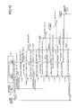
- FIG. 11 is a sequence chart of an exemplary flow execution process of the first embodiment.
- the browser 210 sends the flow execution request for substantializing the scan delivery service to the flow executing unit 131 (step S 1101 ).
- this flow execution request includes the app ID “app 001 ” of the app information 1000 for providing the scan delivery service and the flow ID “flow 001 ” of the process content for substantializing the scan delivery service in collaboration with the storage service A.
- the flow execution request includes the electronic file generated by scanning and the folder ID of the storage destination folder of the electronic file in the external storage system 301 .
- the flow executing unit 131 acquires the process content of the flow ID “flow 001 ” from the app information 1000 of the app ID “app 001 ” included in the flow execution request through the app administering unit 120 (step S 1102 ). Said differently, the flow executing unit 131 acquires the process content 1100 illustrated in FIG. 6A .
- the flow execution unit 131 requests the component administering unit 132 to acquire the component in accordance with the acquired process content (step S 1103 ). More specifically, the flow executing unit 131 requests the component administering unit 132 to acquire the OCR component 1332 A based on “.to(“process:ocrA”)” designated next to “From(“file:input”)” of the process content illustrated in FIG. 6A .
- the component administering unit 132 When the component administering unit 132 receives the acquisition request to acquire the OCR component 1332 A, the component administering unit 132 generates the OCR component 1332 A (step S 1104 ).
- the OCR component 1332 A is generated by using an API for generating a component defined in the component common I/F 1330 .
- the component administering unit 132 When the OCR component 1332 A is generated, the component administering unit 132 returns an OCR component 1332 A to the flow executing unit 131 . For example, the component administering unit 132 returns the address in the memory (e.g., the RAM 14 ), on which the OCR component 1332 A is deployed, to the flow executing unit 131 .
- the memory e.g., the RAM 14
- the flow executing unit 131 designates data and requests the generated OCR component 1332 A to execute the process (step S 1105 ).
- the data type of the designated data is “InputStream”.
- the designated data is an electronic file transferred from the browser 210 .
- the flow executing unit 131 requests to execute the process by transferring the electronic file, which is transferred as the data type of “InputStream” from the browser 210 , simply as “data” (without convincing the data type) to the OCR component 1332 .
- this electronic file transferred without convincing the data type is simply indicated as the “data”.
- the OCR component 1332 A When the OCR component 1332 A receives the execution request of the process, in which the data are designated, the OCR component 1332 A executes the process to the designated data (step S 1106 ). More specifically, the OCR component 1332 A requests the OCR process 151 of the document servicing unit 150 to process, and the OCR process is executed for the data for which the OCR process is designated.
- the OCR component 1332 A returns data indicative of the electronic file provided with the OCR process to the flow executing unit 131 .
- the flow executing unit 131 requests the component administering unit 132 to acquire the component in accordance with the acquired process content (step S 1107 ). More specifically, the flow executing unit 131 requests the component administering unit 132 to acquire the translation component 1333 A based on “.to(“process:transA”)” designated next to “.to(“process:ocrA”)” of the process content 1100 illustrated in FIG. 6A .
- the component administering unit 132 When the component administering unit 132 receives the acquisition request to acquire a translation component 1333 A, the component administering unit 132 generates the translation component 1333 A (step S 1108 ).
- the translation component 1333 A is generated by using the API for generating the component defined in the component common I/F 1333 .
- the component administering unit 132 When the translation component 1333 A is generated, the component administering unit 132 returns the translation component 1333 A to the flow executing unit 131 . For example, the component administering unit 132 returns the address in the memory (e.g., the RAM 14 ), on which the translation component 1333 A is deployed, to the flow executing unit 131 .
- the memory e.g., the RAM 14
- the flow executing unit 131 designates data and requests the generated translation component 1333 A to execute the process (step S 1109 ).
- the data designated here is the electronic file provided with the OCR process.
- the translation component 1333 A When the translation component 1333 A receives the execution request of the process, in which the data are designated, the translation component 1333 A executes the process to the designated data (step S 1110 ). More specifically, the translation component 1333 A requests the translating process 152 of the document servicing unit 150 to process and executes a translating process to a predetermined language for the data designated by the translating process 152 .
- the translation component 1333 A returns data indicative of the electronic file provided with the translating process to the flow executing unit 131 .
- the flow executing unit 131 requests the component administering unit 132 to acquire the component in accordance with the acquired process content 1100 (step S 1111 ). More specifically, the flow executing unit 131 requests the component administering unit 132 to acquire the delivery component 1331 A based on “.to(“storage:uploadFileA”)” designated next to “.to(“process:transA”)” of the process content 1100 illustrated in FIG. 6A .
- the component administering unit 132 When the component administering unit 132 receives the acquisition request to acquire the delivery component 1331 A, the component administering unit 132 generates the delivery component 1331 A (step S 1112 ).
- the delivery component 1331 A is generated by using the API for generating the component defined in the component common I/F 1330 .
- the component administering unit 132 When the delivery component 1331 A is generated, the component administering unit 132 returns delivery component 1331 A to the flow executing unit 131 .
- the component administering unit 132 may return the address in the memory (e.g., the RAM 14 ), on which the delivery component 1331 A is deployed, to the flow executing unit 131 .
- the flow executing unit 131 designates data and requests the generated delivery component 1331 A to execute the process (step S 1113 ).
- the data designated here is the electronic file provided with the translating process.
- the delivery component 1331 A executes the process to the designated data (step S 1114 ).
- the delivery component 1331 A requests to execute the delivery of the data to a file processing unit 1701 of a storage-service A collaborating unit 1601 using an API for file storage defined as a common I/F 1711 .
- the delivery component 1331 A requests the file processing unit 1701 of the storage-service A collaborating unit 1601 to perform the delivery execution of the data using the API of “service-a/process/folder” illustrated in FIG. 5A .
- the electronic file provided with the translating process is stored in the folder of the folder ID input in the storage-destination-folder-ID input column 3300 illustrated in FIG. 10 in the storage service A.
- the delivery component 1331 A returns the data indicative of the executed result of the delivery execution to the flow executing unit 131 .
- the flow executing unit 131 returns the processed result of a sequence of processes (the process flow) 131 acquired based on the acquired process content 1100 to the browser 210 (step S 1115 ). With this, the user of the image forming apparatus 20 can know that the sequence of processes substantializing the scan delivery service is completed.
- FIG. 12 is a sequence chart of another exemplary flow execution process of the first embodiment.
- FIG. 12 is a case where an error occurs in the OCR process included in the sequence of processes (the process flow) for substantializing the scan delivery service of the first embodiment.
- the point where the error occurs is not limited thereto. Even if the error occurs in any process from among the processes included in the process flow substantializing the scan delivery service, a process described below is similarly applicable.
- the browser 210 sends the flow execution request for substantializing the scan delivery service to the flow executing unit 131 (step S 1201 ).
- this flow execution request includes the app ID “app 001 ” of the app information 1000 for providing the scan delivery service and the flow ID “flow 001 ” of the process content for substantializing the scan delivery service in collaboration with the storage service A.
- the flow execution request includes the electronic file generated by scanning and the folder ID of the storage destination folder of the electronic file in the external storage system 301 .
- the flow executing unit 131 acquires the process content of the flow ID “flow 001 ” from the app information 1000 of the app ID “app 001 ” included in the flow execution request through the app administering unit 120 (step S 1202 ). Said differently, the flow executing unit 131 acquires the process content 1100 illustrated in FIG. 6A .
- the flow executing unit 131 requests the component administering unit 132 to acquire the component in accordance with the acquired process content 1100 (step S 1203 ). More specifically, the flow executing unit 131 requests the component administering unit 132 to acquire the OCR component 1332 A based on “.to(“process:ocrA”)” designated next to “From(“file:input”)” of the process content 1100 illustrated in FIG. 6A .
- the component administering unit 132 When the component administering unit 132 receives the acquisition request to acquire the OCR component 1332 A, the component administering unit 132 generates the OCR component 1332 A (step S 1204 ).
- the OCR component 1332 A is generated by using the API for generating the component defined in the component common I/F 1330 .
- the component administering unit 132 When the OCR component 1332 A is generated, the component administering unit 132 returns the OCR component 1332 A to the flow executing unit 131 . For example, the component administering unit 132 returns the address in the memory (e.g., the RAM 14 ), on which the OCR component 1332 A is deployed, to the flow executing unit 131 .
- the memory e.g., the RAM 14
- the flow executing unit 131 designates the data and requests the generated OCR component 1332 A to execute the process (step S 1205 ).
- the data type of the designated data is “InputStream”.
- the designated data is the electronic file transferred from the browser 210 .
- the OCR component 1332 A When the OCR component 1332 A receives the execution request of the process, in which the data are designated, the OCR component 1332 A executes the process to the designated data (step S 1206 ). More specifically, the OCR component 1332 A requests the OCR process 151 of the document servicing unit 150 to process, and the OCR process is executed for the data for which the OCR process is designated.
- the flow executing unit 131 When the flow executing unit 131 receives data indicating that the error occurs, the flow executing unit 131 refers to the substitute-flow administering table 2000 and acquires a substitute flow ID associated with the flow ID of the process content 1100 acquired in step S 1202 (step S 1207 ). More specifically, the flow executing unit 131 B acquires the substitute flow ID “flow 002 ” associated with the flow ID “flow 001 ” of the process content 1100 in the substitute-flow administering table 2000 .
- the flow executing unit 131 acquires the process content (a substitute flow content) of the substitute flow ID “flow 002 ” through the app administering unit 120 (step S 1208 ). Said differently, the flow executing unit 131 acquires the process content 1200 illustrated in FIG. 68 .
- the service providing system 10 of the first embodiment acquires another process content associated with the process content in the substitute-flow administering table 2000 in a case where the error or the like occurs in the sequence of processes based on the process content.
- the flow executing unit 131 requests the component administering unit 132 to acquire the component in accordance with the acquired process content 1200 (step S 1209 ). More specifically, the flow executing unit 131 requests the component administering unit 132 to acquire an OCR component 1332 B based on “.to(“process:ocrB”)” designated next to “From(“file:input”)” of the process content 1200 illustrated in FIG. 6B .
- the component administering unit 132 When the component administering unit 132 receives the acquisition request to acquire the OCR component 1332 B, the component administering unit 132 generates the OCR component 1332 B (step S 1210 ).
- the OCR component 1332 B is generated by using an API for generating a component defined in the component common I/F 1330 .
- the component administering unit 132 When the OCR component 1332 B is generated, the component administering unit 132 returns the OCR component 1332 B to the flow executing unit 131 . For example, the component administering unit 132 returns the address in the memory (e.g., the RAM 14 ), on which the OCR component 1332 B is deployed, to the flow executing unit 131 .
- the memory e.g., the RAM 14
- the flow executing unit 131 designates the data and requests the generated OCR component 1332 B to execute the process (step S 1211 ).
- the OCR component 1332 B executes the process to the designated data (step S 1212 ). More specifically, the OCR component 1332 B requests the OCR process 151 of the document servicing unit 150 to process, and the OCR process is executed for the data for which the OCR process is designated.
- the OCR component 1332 B returns data indicative of the electronic file provided with the OCR process to the flow executing unit 131 .
- the flow executing unit 131 requests the component administering unit 132 to acquire the component in accordance with the acquired process content 1200 (step S 1213 ). More specifically, the flow executing unit 131 requests the component administering unit 132 to acquire the translation component 1333 B based on “.to(“process:transB”)” designated next to “.to(“process:ocrB”)” of the process content 1200 illustrated in FIG. 6B .
- the component administering unit 132 When the component administering unit 132 receives the acquisition request to acquire a translation component 1333 B, the component administering unit 132 generates the translation component 13333 (step S 1214 ).
- the translation component 13333 is generated by using the API for generating a component defined in the component common I/F 1333 .
- the component administering unit 132 When the translation component 1333 B is generated, the component administering unit 132 returns the translation component 13333 to the flow executing unit 131 . For example, the component administering unit 132 returns the address in the memory (e.g., the RAM 14 ), on which the translation component 1333 B is deployed, to the flow executing unit 131 .
- the memory e.g., the RAM 14
- the flow executing unit 131 designates the data and requests the generated translation component 13333 to execute the process (step S 1215 ).
- the data designated here is the electronic file provided with the OCR process.
- the translation component 13333 executes the process to the designated data (step S 1216 ). More specifically, the translation component 13333 requests the translating process 152 of the document servicing unit 150 to process and executes a translating process to the predetermined language for the data designated by the translating process 152 .
- the translation component 1333 B returns data indicative of the electronic file provided with the translating process to the flow executing unit 131 .
- the flow executing unit 131 requests the component administering unit 132 to acquire the component in accordance with the acquired process content 1200 (step S 1217 ). More specifically, the flow executing unit 131 requests the component administering unit 132 to acquire the delivery component 1331 B based on “.to(“storage:uploadFileB”)” designated next to “.to(“process:transB”)” of the process content 1200 illustrated in FIG. 6B .
- the component administering unit 132 When the component administering unit 132 receives the acquisition request to acquire the delivery component 13313 , the component administering unit 132 generates the delivery component 1331 B (step S 1218 ).
- the delivery component 1331 B is generated by using the API for generating a component defined in the component common I/F 1330 .
- the component administering unit 132 When the delivery component 1331 B is generated, the component administering unit 132 returns the delivery component 13313 to the flow executing unit 131 .
- the component administering unit 132 returns the address in the memory (e.g., the RAM 14 ), on which the delivery component 13313 is deployed, to the flow executing unit 131 .
- the flow executing unit 131 designates the data and requests the generated delivery component 13313 to execute the process (step S 1219 ).
- the data designated here is the electronic file provided with the translating process.
- the delivery component 1331 B executes the process to the designated data (step S 1220 ).
- the delivery component 13313 requests to execute the delivery of the data to a file processing unit 1702 of a storage-service B collaborating unit 1602 using an API for file storage defined as a common I/F 1712 .
- the delivery component 13313 requests the file processing unit 1702 of the storage-service B collaborating unit 1602 to perform the delivery execution of the data using the API of “service-b/process/folder” illustrated in FIG. 5A .
- the electronic file provided with the translating process is stored in the folder of the folder ID input in the storage-destination-folder-ID input column 3300 illustrated in FIG. 10 in the storage service B.
- the delivery component 13313 returns the data indicative of the executed result of the delivery execution to the flow executing unit 131 .
- the flow executing unit 131 returns the processed result of the sequence of processes (the substitute flow) acquired based on the acquired process content 1200 as the substitute flow content of the process content 1100 to the browser 210 (step S 1221 ). With this, the user of the image forming apparatus 20 can know that the error occurs in the sequence of processes substantializing the scan delivery service, and the substitute flow is executed.
- the second embodiment differs from the first embodiment in that, in a case where the substitute flow is executed, a processed result in conformity with the type of the substitute flow is returned to the browser 210 .
- portions having substantially the same functions as those of the first embodiment and portions performing the same processes as those of the first embodiment are designated by the same reference symbols as those of the first embodiment, and description of these portions is omitted.
- FIG. 13 described is a processing block of the logic processing unit 130 of the service providing system 10 included in the information processing system 1 of the second embodiment.
- FIG. 13 is a processing block diagram of an exemplary logic processing unit of the second embodiment.
- the logic processing unit 130 of the service providing system 10 illustrated in FIG. 13 includes a flow executing unit 131 A.
- the logic processing unit 130 of the service providing system 10 illustrated in FIG. 13 uses a substitute-flow administering table 2000 A.
- the flow executing unit 131 A refers to the substitute-flow administering table 2000 A and returns the processed result corresponding to the substitute flow type of the substitute flow.
- FIG. 14 illustrates an exemplary substitute-flow administering table of the second embodiment.
- the data items of the substitute-flow administering table 2000 A illustrated in FIG. 14 further includes a substitute flow type. Said differently, in the substitute-flow administering table 2000 A, the substitute flow type is associated with the substitute flow ID.
- the substitute flow type is information indicative of the type of the processed result in a case where the sequence of processes (the substitute flow) is executed based on the process content (the substitute flow) indicated by the substitute flow ID.
- the flow executing unit 131 returns the processed result indicative of “success” as the processed result of the substitute flow to the browser 210 .
- the flow executing unit 131 returns the processed result indicative of “failure” as the processed result of the substitute flow to the browser 210 .
- FIG. 15 is a sequence chart of an exemplary flow execution process of the second embodiment. Because the processes of steps S 1201 to S 1220 are similar to the processes of the first embodiment, the description of these processes is omitted.
- the flow executing unit 131 A refers to the substitute-flow administering table 2000 A and acquires the substitute flow type of the executed substitute flow (step S 1501 ). More specifically, the flow executing unit 131 A acquires the substitute flow type “type 1 ” associated with the substitute flow ID “flow 002 ” in the substitute-flow administering table 2000 A.
- the flow executing unit 131 A returns the processed result corresponding to the acquired substitute flow type to the browser 210 (step S 1502 ). More specifically, the flow executing unit 131 A returns the processed result indicative of “success” to the browser 210 in response to the acquired substitute flow type “type 1 ”.
- the processed result corresponding to the substitute flow type of the substitute flow is returned to the image forming apparatus 20 .
- an appropriate processed result corresponding to the type and the content of the executed substitute flow to the image forming apparatus 20 is returned to the image forming apparatus 20 .
- the substitute flow ID may be caused to be associated with the substitute flow type “type 1 ” in the substitute-flow administering table 2000 A.
- the processed result indicating “success” can be returned to the browser 210 in a case where the substitute flow substantializing the processes similar to the processes of the process flow are executed.
- the substitute flow ID may be caused to be associated with the substitute flow type “type 2 ” in the substitute-flow administering table 2000 A.
- the service providing system 10 of the second embodiment 10 can return the processed result indicative of “failure” to the browser 210 in a case where the substitute flow is executed.
- the third embodiment differs from the first embodiment at points that the error generated in the process flow is determined to be a recoverable error or not, and that another process content is acquired in response to this determined result.
- portions having substantially the same functions as those of the first embodiment and portions performing the same processes as those of the first embodiment are designated by the same reference symbols as those of the first embodiment, and description of these portions is omitted.
- FIG. 16 described is the processing block of the logic processing unit 130 of the service providing system 10 included in the information processing system 1 of the third embodiment.
- FIG. 16 is a processing block diagram of an exemplary logic processing unit of the third embodiment.
- the logic processing unit 130 of the service providing system 10 illustrated in FIG. 16 includes a flow executing unit 131 B.
- the logic processing unit 130 of the service providing system 10 illustrated in FIG. 16 uses a substitute-flow administering table 2000 B.
- the flow executing unit 131 B determines whether the error is a recoverable error. Then, the flow executing unit 131 B refers to the substitute-flow administering table 2000 B and acquires the substitute flow ID or an exceptional flow ID in response to the determined result.
- the exceptional flow ID is a flow ID of the process content (an exceptional flow content), which is executed in the case where the unrecoverable error occurs in the process flow.
- an exceptional flow content a content of a process substantializing, for example, an output of error information and an error report.
- FIG. 17 illustrates an exemplary substitute-flow administering table of the third embodiment.
- the data items of the substitute-flow administering table 2000 B illustrated in FIG. 17 further includes the exceptional flow ID. Said differently, in the substitute-flow administering table 2000 B, the substitute flow ID and the exceptional flow ID are associated with the flow ID.
- the substitute flow ID “flow 002 ” and the exceptional flow ID “flow 900 ” are associated with the flow ID “flow 001 ”.
- the flow executing unit 131 B can acquire the process content (the substitute flow content) of the substitute flow ID or the process content (the exceptional flow content) of the exceptional flow ID.
- FIG. 18 is a sequence chart of an exemplary flow execution process of the third embodiment. Because the processes of steps S 1201 to S 1206 are similar to the processes of the first embodiment, the description of these processes is omitted.
- the flow executing unit 131 B determines whether the error is a recoverable error (step S 1801 ).
- the recoverable error is the error type, in which the substitute flow may be executed.
- the unrecoverable error is the error type, in which the substitute flow may not be executed.
- the unrecoverable error may include a case where the substitute flow does not exist, for example.
- the flow executing unit 131 B executes the processes of steps S 1802 to step S 1804 .
- the flow executing unit 131 B executes the processes of steps S 1805 to step S 1807 .
- the flow executing unit 131 B refers to the substitute-flow administering table 2000 B and acquires the substitute flow ID associated with the flow ID of the process content 1100 (step S 1802 ). More specifically, the flow executing unit 131 B acquires the substitute flow ID “flow 002 ” associated with the flow ID “flow 001 ” of the process content 1100 in the substitute-flow administering table 2000 B.
- the flow executing unit 131 B acquires the process content (the substitute flow content) of the substitute flow ID “flow 002 ” through the app administering unit 120 (step S 1803 ). Said differently, the flow executing unit 131 B acquires the process content illustrated in FIG. 6B .
- the flow executing unit 131 B executes the substitute flow based on the acquired process content 1200 (step S 1804 ). In this case, the processes similar to steps S 1209 to S 1221 are conducted.
- the flow executing unit 131 B refers to the substitute-flow administering table 2000 B and acquires the exceptional flow ID associated with the flow ID of the process content 1100 (step S 1805 ). More specifically, the flow executing unit 131 B acquires the substitute flow ID “flow 900 ” associated with the flow ID “flow 001 ” of the process content 1100 in the substitute-flow administering table 2000 B.
- the flow executing unit 131 B acquires the exceptional flow ID
- the flow executing unit 131 B acquires the process content (the exceptional flow content) of the exceptional flow ID “flow 900 ” through the app administering unit 120 (step S 1806 ).
- the flow executing unit 131 B executes the exceptional flow based on the acquired exceptional flow content (step S 1807 ).
- the substitute flow or the exceptional flow can be executed depending on whether the occurred error is recoverable or unrecoverable. Therefore, in the service providing system 10 of the third embodiment, for example, in a case where an unrecoverable serious error occurs in the process flow, the exceptional flow for reporting the occurrence of the error to the image forming apparatus 20 may be executed.
- the fourth embodiment differs from the first embodiment at a point of generating, in a case where the error or the like occurs in the process flow, the process content (the substitute flow content) causing the other component (the substitute component) previously associated with the component, in which the error occurs, to be executed.
- the substitute flow content for causing the substitute component to be executed is dynamically generated.
- FIG. 19 described is the processing block of the logic processing unit 130 of the service providing system 10 included in the information processing system 1 of the fourth embodiment.
- FIG. 19 is a processing block diagram of an exemplary logic processing unit of the fourth embodiment.
- the logic processing unit 130 of the service providing system 10 illustrated in FIG. 19 includes a flow executing unit 131 C and a substitute-flow content-generating unit 134 .
- the logic processing unit 130 of the service providing system 10 illustrated in FIG. 19 uses a substitute-component administering table 4000 .
- the flow executing unit 131 C acquires the substitute component ID of the component, in which the error or the like occurs, from the substitute-component administering table 4000 .
- the flow executing unit 131 requests the substitute-flow content-generating unit 134 to generate the process content (the substitute flow content) for causing the component of the acquired substitute component ID to be executed.
- the substitute-flow content-generating unit 134 generates, in response to the request by the flow executing unit 131 C, the substitute flow content based on the substitute component ID included in the request.
- FIG. 20 illustrates an exemplary substitute-component administering table of the fourth embodiment.
- the data items of the substitute-component administering table 4000 illustrated in FIG. 20 includes a flow ID, a component ID, and a substitute component ID.
- the component ID for uniquely identifying the component and the substitute component ID indicative of the component ID of the substitute component are associated for each flow ID.
- the substitute component is executed in a case where an error or the like occurs in the component and is, for example, another component performing a process similar to the component in which the error or the like occurs.
- the substitute component ID “ocrB” is associated with the component ID “ocrA” in the flow ID “flow 001 ”.
- the error or the like occurs in the component of the component ID “ocrA” in the process flow of the flow ID “flow 001 ”, it is possible to generate the process content causing the component of the substitute component ID “ocrB” to be executed.
- the substitute component ID “uploadFileA” is associated with the component ID “uploadFileB” in, for example, the flow ID “flow 002 ”.
- the error or the like occurs in the component of the component ID “uploadFileB” in the process flow of the flow ID “flow 002 ”, it is possible to generate the process content causing the component of the substitute component ID “uploadFileA” to be executed.
- the component ID and the substitute component ID whose flow IDs are “-” are used in a case where there is no component ID of the component, in which the error or the like occurs in the corresponding flow ID.
- the substitute component ID “transC” is used to generate the process content (the substitute flow content).
- FIG. 21 is a sequence chart of an exemplary flow execution process of the fourth embodiment. Because the processes of steps S 1201 to S 1206 are similar to the processes of the first embodiment, the description of these processes is omitted.
- the flow executing unit 131 C After the flow executing unit 131 C receives data indicating that the error occurs, the flow executing unit 131 C refers to the substitute-component administering table 4000 and acquires the corresponding substitute component ID (step S 2101 ). Said differently, the flow executing unit 131 C acquires the substitute component ID “ocrB” associated with the flow ID “flow 001 ” of the process content 1100 acquired in step S 1202 and the component ID “ocrA” of the OCR component 1332 A.
- the flow executing unit 131 C sends a generation request to generate the substitute flow content including the acquired substitute component ID “ocrB” to the substitute-flow content-generating unit 134 (step S 2102 ).
- the substitute-flow content-generating unit 134 After the substitute-flow content-generating unit 134 receives the generation request of the substitute flow content, the substitute-flow content-generating unit 134 generates the substitute flow content based on the substitute component ID “ocrB” included in the generation request (step S 2103 ). Said differently, the substitute-flow content-generating unit 134 changes the component ID “ocrA” included in the process content 1100 to the substitute component ID “ocrB” to generate the process content 1300 illustrated in FIG. 22 .
- the substitute-flow content-generating unit 134 returns the generated process content 1300 to the flow executing unit 131 C.
- the flow executing unit 131 requests the component administering unit 132 to acquire the component in accordance with the acquired process content 1300 (step S 2104 ). More specifically, the flow executing unit 131 C requests the component administering unit 132 to acquire the OCR component 1332 B based on “.to(“process:ocrB”)” designated in the process content 1300 illustrated in FIG. 22 .
- the component administering unit 132 When the component administering unit 132 receives the acquisition request to acquire the OCR component 1332 B, the component administering unit 132 generates the OCR component 1332 B (step S 2105 ). When the OCR component 1332 B is generated, the component administering unit 132 returns the OCR component 1332 B to the flow executing unit 131 C.
- the flow executing unit 131 C designates the data and requests the generated OCR component 1332 B to execute the process (step S 2106 ).
- the OCR component 1332 B When the OCR component 1332 B receives the execution request of the process, in which the data are designated, the OCR component 1332 B executes the process to the designated data (step S 2107 ). The OCR component 1332 B returns data indicative of the electronic file provided with the OCR process to the flow executing unit 131 C.
- the flow executing unit 131 C requests the component administering unit 132 to acquire the component in accordance with the acquired process content 1300 (step S 2108 ). More specifically, the flow executing unit 131 C requests the component administering unit 132 to acquire the translation component 1333 A based on “.to(“process:transA”)” designated next to “.to(“process:ocrB”)” of the process content 1300 illustrated in FIG. 22 .
- the component administering unit 132 When the component administering unit 132 receives the acquisition request to acquire a translation component 1333 A, the component administering unit 132 generates the translation component 1333 A (step S 2109 ). When the translation component 1333 A is generated, the component administering unit 132 returns the translation component 1333 A to the flow executing unit 131 C.
- the flow executing unit 131 C designates data and requests the generated translation component 1333 A to execute the process (step S 210 ).
- the data designated here is the electronic file provided with the OCR process.
- the translation component 1333 A When the translation component 1333 A receives the execution request of the process, in which the data are designated, the translation component 1333 A executes the process to the designated data (step S 2111 ). The translation component 1333 A returns data indicative of the electronic file provided with the translating process to the flow executing unit 131 C.
- the flow executing unit 131 C requests the component administering unit 132 to acquire the component in accordance with the acquired process content 1300 (step S 2112 ). More specifically, the flow executing unit 131 C requests the component administering unit 132 to acquire the delivery component 13313 based on “.to(“storage:uploadFileA”)” designated next to “.to(“process:transA”)” of the process content 1300 illustrated in FIG. 22 .
- the component administering unit 132 When the component administering unit 132 receives the acquisition request to acquire the delivery component 1331 A, the component administering unit 132 generates the delivery component 1331 A (step S 2113 ). When the delivery component 1331 A is generated, the component administering unit 132 returns the delivery component 1331 A to the flow executing unit 131 C.
- the flow executing unit 131 C designates data and requests the generated translation component 1333 A to execute the process (step S 2114 ).
- the data designated here is the electronic file provided with the translating process.
- the delivery component 1331 A executes the process to the designated data (step S 2115 ).
- the delivery component 1331 requests the file processing unit 1701 of the storage-service A collaborating unit 1601 to execute the data delivery using the API for the file storage defined as the common I/F 1711 .
- the electronic file provided with the translating process is stored in a predetermined folder of the storage service A.
- the delivery component 1331 A returns the data indicative of the executed result of the delivery execution to the flow executing unit 131 C.
- the flow executing unit 131 C returns the processed result of the sequence of processes (the substitute flow) acquired based on the process content 1300 to the browser 210 (step S 2216 ). With this, the user of the image forming apparatus 20 can know that the error occurs in the sequence of processes (the process flow) substantializing the scan delivery service and the substitute component is executed in place of the component, in which the error occurs.
- the process content (the substitute flow content) causing the substitute component of the component to be executed is generated.
- the process content (the substitute flow content) based on the generated process content (the substitute flow content) is executed.
- the substitute component performing a process similar to the component can be executed.
- the fifth embodiment differs from the fourth embodiment in that, in a case where the substitute flow is executed, a processing result in conformity with the type of the substitute flow is returned to the browser 210 .
- portions having substantially the same functions as the functions in the fourth embodiment and portions performing the same processes as the processes in the fourth embodiment are designated by the same reference symbols as the reference symbols in the fourth embodiment, and description of these portions is omitted.
- FIG. 23 described is the processing block of the logic processing unit 130 of the service providing system 10 included in the information processing system 1 of the fifth embodiment.
- FIG. 23 is a processing block diagram of an exemplary logic processing unit of the fifth embodiment.
- the logic processing unit 130 of the service providing system 10 illustrated in FIG. 23 includes a flow executing unit 131 D and a substitute-flow content-generating unit 134 A.
- the logic processing unit 130 of the service providing system 10 illustrated in FIG. 23 uses a substitute-component administering table 4000 A.
- the flow executing unit 131 D acquires the substitute component ID and the substitute component type of the component, in which the error occurs, from the substitute-component administering table 4000 A.
- the flow executing unit 131 requests the substitute-flow content-generating unit 134 A to generate the process content (the substitute flow content) for causing the component of the acquired substitute component ID to be executed.
- the flow executing unit 131 D acquires the substitute flow type from the process content and returns the processed result corresponding to the substitute flow type.
- the substitute-flow content-generating unit 134 A generates, in response to the request by the flow executing unit 131 D, the substitute flow content based on the substitute component ID and the substitute component type included in the request.
- FIG. 24 illustrates an exemplary substitute-component administering table of the fifth embodiment.
- the data items of the substitute-flow administering table 4000 A illustrated in FIG. 24 further includes a substitute component type as the data item.
- the substitute component type is associated with the flow ID, the component ID, and the substitute component ID.
- the substitute component type is information indicative of a type of the processed result of the substitute flow in a case where the component of the substitute component ID is executed.
- the flow executing unit 131 D returns the processed result indicative of “success” as the processed result of the substitute flow to the browser 210 .
- the flow executing unit 131 D returns the processed result indicative of “failure” as the processed result of the substitute flow to the browser 210 .
- FIG. 25 is a sequence chart of an exemplary flow execution process of the fifth embodiment.
- the flow executing unit 131 D After the flow executing unit 131 D receives data indicating that the error occurs, the flow executing unit 131 D refers to the substitute-component administering table 4000 and acquires the corresponding substitute component ID (step S 2501 ). Said differently, the flow executing unit 131 D acquires the substitute component ID “ocrB” and the substitute component type “type 1 ”, which are associated with the flow ID “flow 001 ” of the process content 1100 and the component ID “ocrA” of the OCR component 1332 A.
- the flow executing unit 131 D sends a generation request to generate the substitute flow content including the acquired substitute component ID “ocrB” and the substitute component type “type 1 ” to the substitute-flow content-generating unit 134 A (step S 2502 ).
- the substitute-flow content-generating unit 134 A After the substitute-flow content-generating unit 134 A receives the generation request of the substitute flow content, the substitute-flow content-generating unit 134 A generates the substitute flow content based on the substitute component ID “ocrB” and the substitute component type “type 1 ” included in the generation request (step S 2103 ). Said differently, the substitute-flow content-generating unit 134 A changes the component ID “ocrA” included in the process content 1100 to the substitute component ID “ocrB” and adds the substitute component type “type 1 ” to generate the process content 1400 illustrated in FIG. 26 .
- the substitute-flow content-generating unit 134 A returns the generated process content 1400 to the flow executing unit 131 D.
- the substitute flow type of flowtype:“type 1 ” is added to the process content 1100 based on the substitute component type “type 1 ” as indicated by a broken line 1401 .
- “.to(“process:ocrA”)” is changed to “.to(“process:ocrB”)” in the process content as indicated by a broken line 1402 .
- the process can be performed by the OCR component 1332 B and the processed result corresponding to the substitute flow type “type 1 ” can be returned to the browser 210 .
- steps S 2104 to S 2115 are similar to the processes of the fourth embodiment, the description of these processes is omitted.
- the flow executing unit 131 D acquires the substitute flow type of the executed substitute flow (step S 2504 ). More specifically, the flow executing unit 131 D acquires the substitute flow type “type 1 ” from “flowtype:“type 1 ”” included in the process content 1400 of the executed substitute flow.
- the flow executing unit 131 A returns the processed result corresponding to the acquired substitute flow type to the browser 210 (step S 2505 ). More specifically, the flow executing unit 131 D returns the processed result indicative of “success” to the browser 210 in response to the acquired substitute flow type “type 1 ”.
- the processed result corresponding to the substitute flow type of the substitute flow is returned to the image forming apparatus 20 .
- the substitute flow type is designated based on the substitute component type associated with the substitute component ID.
- the sixth embodiment differs from the fourth embodiment at points that the error generated in the component executing each process is determined to be a recoverable error or not, and that the component ID of another component is acquired in response to this determined result.
- portions having substantially the same functions as the functions in the fourth embodiment and portions performing the same processes as the processes in the fourth embodiment are designated by the same reference symbols as the reference symbols in the fourth embodiment, and description of these portions is omitted.
- FIG. 27 described is the processing block of the logic processing unit 130 of the service providing system 10 included in the information processing system 1 of the sixth embodiment.
- FIG. 27 is a processing block diagram of an exemplary logic processing unit of the sixth embodiment.
- the logic processing unit 130 of the service providing system 10 illustrated in FIG. 27 includes a flow executing unit 131 E and the substitute-flow content-generating unit 134 B. Further, the component group 133 of the logic processing unit 130 of the service providing system 10 illustrated in FIG. 27 includes an exceptional component 1334 A or the like.
- the logic processing unit 130 of the service providing system 10 illustrated in FIG. 27 uses a substitute-component administering table 4000 B.
- the flow executing unit 131 E determines whether the error is a recoverable error. Then, the flow executing unit 131 E refers to the substitute-component administering table 4000 B and acquires the substitute flow ID or the exceptional flow ID in response to the determined result.
- the exceptional component ID is a component ID of another component (the exceptional component 1334 A) executed in a case where the unrecoverable error occurs in the component executing each process in the process flow.
- the exceptional component 1334 A executes processes such as an output of error information and an error report.
- the substitute-flow content-generating unit 134 B generates, in response to the request by the flow executing unit 131 E, the substitute flow content based on the substitute component ID and the exceptional component ID included in the request.
- FIG. 28 illustrates an exemplary substitute-component administering table of the sixth embodiment.
- the data items of the substitute-component administering table 4000 B illustrated in FIG. 28 further includes the exceptional component ID as the data item.
- the exceptional component ID is associated with the flow ID and the component ID in addition to the substitute component ID associated with the flow ID and the component ID.
- the exceptional component ID “exceptA” of the exceptional component 1334 A is associated with the flow ID “flow 001 ” and the component ID “ocrA” in addition to the substitute component ID “ocrB” associated with the flow ID “flow 001 ” and the component ID “ocrA”.
- the exceptional component ID “exceptB” of the exceptional component 1334 B is associated with the flow ID “flow 001 ” and the component ID “uploadFileA” in addition to the substitute component ID “uploadFileB” associated with the flow ID “flow 001 ” and the component ID “uploadFileA”.
- the flow executing unit 131 E can acquire the substitute component ID or the exceptional component ID in response to the error.
- FIG. 29 is a sequence chart of an exemplary flow execution process of the sixth embodiment. Because the processes of steps S 1201 to S 1206 are similar to the processes of the first embodiment, the description of these processes is omitted.
- the flow executing unit 131 E determines whether the error is a recoverable error (step S 2901 ).
- the recoverable error is the error type, in which the component of the substitute component ID may be executed.
- Such an error type includes, for example, a temporary network error.
- the unrecoverable error is the error type, in which the component of the substitute component ID may not be executed.
- Such an error type includes, for example, an error indicating that the data input into the component are incorrect.
- the flow executing unit 131 E executes the processes of steps S 2902 to step S 2905 . In a case where the occurred error is determined to be the unrecoverable error in step S 2901 , the flow executing unit 131 E executes the processes of steps S 2906 to step S 2913 .
- the flow executing unit 131 E refers to the substitute-component administering table 4000 B and acquires the corresponding substitute component ID (step S 2902 ). Said differently, the flow executing unit 131 E acquires the substitute component ID “ocrB” associated with the flow ID “flow 001 ” of the process content 1100 acquired in step S 1202 and the substitute component ID “ocrB” associated with the component ID “ocrA” of the OCR component 1332 A.
- the flow executing unit 131 E sends a generation request to generate the substitute flow content including the acquired substitute component ID “ocrB” to the substitute-flow content-generating unit 134 B (step S 2903 ).
- the substitute-flow content-generating unit 134 B After the substitute-flow content-generating unit 134 B receives the generation request of the substitute flow content, the substitute-flow content-generating unit 134 B generates the substitute flow content based on the substitute component ID “ocrB” included in the generation request (step S 2904 ). Said differently, the substitute-flow content-generating unit 134 changes the component ID “ocrA” included in the process content 1100 to the substitute component ID “ocrB” to generate the process content 1300 illustrated in FIG. 22 .
- the substitute-flow content-generating unit 134 B returns the generated process content 1300 to the flow executing unit 131 C.
- the flow executing unit 131 E executes the substitute flow based on the acquired process content 1300 (step S 2905 ). In this case, the processes similar to steps S 2104 to S 2116 are conducted.
- the flow executing unit 131 E refers to the substitute-component administering table 4000 B and acquires the exceptional component ID (step S 2906 ). Said differently, the flow executing unit 131 E acquires the exceptional component ID “exceptA” associated with the flow ID “flow 001 ” of the process content 1100 acquired in step S 1202 and the component ID “ocrA” of the OCR component 1332 A.
- the flow executing unit 131 E sends a generation request to generate the substitute flow content including the acquired exceptional component ID “exceptA” to the substitute-flow content-generating unit 134 B (step S 2907 ).
- the substitute-flow content-generating unit 134 B After the substitute-flow content-generating unit 134 B receives the generation request of the substitute flow content, the substitute-flow content-generating unit 134 B generates the substitute flow content based on the exceptional component ID “exceptA” included in the generation request (step S 2908 ). Said differently, the substitute-flow content-generating unit 134 B generates a process content 1500 illustrated in FIG. 30 .
- the substitute-flow content-generating unit 134 B returns the generated process content 1500 to the flow executing unit 131 E.
- the flow execution unit 131 E requests the component administering unit 132 to acquire the component in accordance with the acquired process content 1500 (step S 2909 ). More specifically, the flow executing unit 131 E requests the component administering unit 132 to acquire the exceptional component 1334 A based on “.to(“process:exceptA”)” designated in the process content 1500 illustrated in FIG. 30 .
- the component administering unit 132 When the component administering unit 132 receives the acquisition request to acquire the exceptional component 1334 A, the component administering unit 132 generates the exceptional component 1334 A (step S 2910 ). When the exceptional component 1334 A is generated, the component administering unit 132 returns the exceptional component 1334 A to the flow executing unit 131 E.
- the flow executing unit 131 E designates data and requests the generated exceptional component 1334 A to execute the process (step S 2911 ).
- the exceptional component 1334 A When the exceptional component 1334 A receives the execution request of the process, in which the data are designated, the exceptional component 1334 A executes the process to the designated data (step S 2912 ).
- the exceptional component 1334 A executes an exceptional process such as an output of error information and an error report.
- the exceptional component 1334 A returns the data indicative of the processed result of the process to the flow executing unit 131 E.
- the flow executing unit 131 E returns the processed result of the sequence of processes (the substitute flow) acquired based on the process content 1500 to the browser 210 (step S 2913 ). With this, the user of the image forming apparatus 20 can know that the unrecoverable error occurs in the sequence of processes (the process flow) substantializing the scan delivery service and the exceptional component is executed in place of the component, in which the error occurs.
- the substitute component ID or the exceptional component ID is acquired in response to whether the error is recoverable.
- the exceptional component performing the exceptional process such as an output of the error information and the error report is executed.
- the exceptional process for reporting the occurrence of the error to the image forming apparatus 20 may be executed.
- the substitute process of the sequence of processes being in collaboration with the external service is enabled to be executed.
- a method carried out based on this disclosure is not limited to the disclosed order of processes of the method.
- the present invention can be implemented in any convenient form, for example using dedicated hardware, or a mixture of dedicated hardware and software.
- the present invention may be implemented as computer software implemented by one or more networked processing apparatuses.
- the network can comprise any conventional terrestrial or wireless communications network, such as the Internet.
- the processing apparatuses can compromise any suitably programmed apparatuses such as a general purpose computer, personal digital assistant, mobile telephone (such as a WAP or 3G-compliant phone) and so on. Since the present invention can be implemented as software, each and every aspect of the present invention thus encompasses computer software implementable on a programmable device.
- the computer software can be provided to the programmable device using any storage medium for storing processor readable code such as a floppy disk, hard disk, CD ROM, magnetic tape device or solid state memory device.
- the hardware platform includes any desired kind of hardware resources including, for example, a central processing unit (CPU), a random access memory (RAM), and a hard disk drive (HDD).
- the CPU may be implemented by any desired kind of any desired number of processor.
- the RAM may be implemented by any desired kind of volatile or non-volatile memory.
- the HDD may be implemented by any desired kind of non-volatile memory capable of storing a large amount of data.
- the hardware resources may additionally include an input device, an output device, or a network device, depending on the type of the apparatus. Alternatively, the HDD may be provided outside of the apparatus as long as the HDD is accessible.
- the CPU such as a cache memory of the CPU
- the RAM may function as a physical memory or a primary memory of the apparatus, while the HDD may function as a secondary memory of the apparatus.”
Landscapes
- Engineering & Computer Science (AREA)
- Multimedia (AREA)
- Signal Processing (AREA)
- General Engineering & Computer Science (AREA)
- Health & Medical Sciences (AREA)
- Biomedical Technology (AREA)
- General Health & Medical Sciences (AREA)
- Facsimiles In General (AREA)
Abstract
Description
Claims (15)
Applications Claiming Priority (4)
| Application Number | Priority Date | Filing Date | Title |
|---|---|---|---|
| JP2015161828 | 2015-08-19 | ||
| JP2015-161828 | 2015-08-19 | ||
| JP2015-215160 | 2015-10-30 | ||
| JP2015215160A JP6657798B2 (en) | 2015-08-19 | 2015-10-30 | Information processing system, information processing apparatus, and information processing method |
Publications (2)
| Publication Number | Publication Date |
|---|---|
| US20170054865A1 US20170054865A1 (en) | 2017-02-23 |
| US9871940B2 true US9871940B2 (en) | 2018-01-16 |
Family
ID=58158020
Family Applications (1)
| Application Number | Title | Priority Date | Filing Date |
|---|---|---|---|
| US15/232,945 Expired - Fee Related US9871940B2 (en) | 2015-08-19 | 2016-08-10 | Information processing system, information processing apparatus, and method for processing information |
Country Status (1)
| Country | Link |
|---|---|
| US (1) | US9871940B2 (en) |
Families Citing this family (4)
| Publication number | Priority date | Publication date | Assignee | Title |
|---|---|---|---|---|
| US10021266B2 (en) * | 2016-08-19 | 2018-07-10 | Kabushiki Kaisha Toshiba | System and method for automated document translation during transmission |
| US10306080B2 (en) | 2016-10-19 | 2019-05-28 | Ricoh Company, Ltd. | Information processing system, information processing apparatus, and program |
| US10992824B2 (en) | 2019-06-11 | 2021-04-27 | Ricoh Company, Ltd. | Information processing system, processing execution method, and service providing system |
| JP7707817B2 (en) * | 2021-10-01 | 2025-07-15 | 富士フイルムビジネスイノベーション株式会社 | Information processing device and program |
Citations (5)
| Publication number | Priority date | Publication date | Assignee | Title |
|---|---|---|---|---|
| JP2006338069A (en) | 2005-05-31 | 2006-12-14 | Hitachi Ltd | Component software operation method and operation platform |
| JP2007164455A (en) | 2005-12-13 | 2007-06-28 | Canon Inc | Information processing apparatus, workflow generation method and program |
| US7551303B2 (en) * | 2003-03-24 | 2009-06-23 | Fuji Xerox Co., Ltd. | Service processing device and method |
| JP5112085B2 (en) | 2008-01-07 | 2013-01-09 | 株式会社日立製作所 | Office flow generation apparatus and method |
| US20130021643A1 (en) * | 2011-07-18 | 2013-01-24 | Jayasimha Nuggehalli | Document Processing Job Control Via A Mobile Device |
-
2016
- 2016-08-10 US US15/232,945 patent/US9871940B2/en not_active Expired - Fee Related
Patent Citations (7)
| Publication number | Priority date | Publication date | Assignee | Title |
|---|---|---|---|---|
| US7551303B2 (en) * | 2003-03-24 | 2009-06-23 | Fuji Xerox Co., Ltd. | Service processing device and method |
| JP2006338069A (en) | 2005-05-31 | 2006-12-14 | Hitachi Ltd | Component software operation method and operation platform |
| US8782666B2 (en) | 2005-05-31 | 2014-07-15 | Hitachi, Ltd. | Methods and platforms for highly available execution of component software |
| JP2007164455A (en) | 2005-12-13 | 2007-06-28 | Canon Inc | Information processing apparatus, workflow generation method and program |
| US7876465B2 (en) | 2005-12-13 | 2011-01-25 | Canon Kabushiki Kaisha | Information processing apparatus and workflow generation method |
| JP5112085B2 (en) | 2008-01-07 | 2013-01-09 | 株式会社日立製作所 | Office flow generation apparatus and method |
| US20130021643A1 (en) * | 2011-07-18 | 2013-01-24 | Jayasimha Nuggehalli | Document Processing Job Control Via A Mobile Device |
Also Published As
| Publication number | Publication date |
|---|---|
| US20170054865A1 (en) | 2017-02-23 |
Similar Documents
| Publication | Publication Date | Title |
|---|---|---|
| US10750044B2 (en) | Information processing system, information processing apparatus, and method for processing information | |
| US10122870B2 (en) | Information processing system, information processing apparatus, and information processing method | |
| US10445489B2 (en) | Information processing system, information processing apparatus, and method for processing information | |
| US10356266B2 (en) | Information processing system, information processing apparatus, and method for processing information | |
| US11150941B2 (en) | Information processing system, information processing apparatus, method for processing information, and recording medium for handling process flow information | |
| US10120758B2 (en) | Information processing system, information processing apparatus, and information processing method for implementing a system rollback process | |
| US10372485B2 (en) | Information processing system, information processing apparatus, method for processing information, and recording medium | |
| US10114940B2 (en) | Information processing system, information processing apparatus, and information processing method | |
| US20150350344A1 (en) | Information processing system, method of processing information, information processing apparatus, and program | |
| US9794447B2 (en) | Service providing system, cooperation processing method, and information processing system | |
| US9876918B2 (en) | Information processing system for generating job execution screen, electronic apparatus, and program | |
| US9871940B2 (en) | Information processing system, information processing apparatus, and method for processing information | |
| US9904499B2 (en) | Information processing system for dynamically adding a process to a sequence of processes and information processing method using same | |
| US10289356B2 (en) | Information processing apparatus, information processing system, method for processing information, and program | |
| US20180060131A1 (en) | Information processing system, information processing apparatus, and information processing method | |
| JP2004274150A (en) | Service processing system and program | |
| US20130057884A1 (en) | Information processing apparatus, computer program, and control method | |
| US20140365430A1 (en) | Information processing apparatus, system, and control method | |
| US20210019199A1 (en) | Information processing system, information processing apparatus, information processing method, and storage medium | |
| US10348926B2 (en) | Information processing system, information processing apparatus, and information processing method | |
| US10725832B2 (en) | Information processing system, information processing apparatus, method for processing information, and information processing program | |
| US10567613B2 (en) | Information processing system, program, and requesting method | |
| US20220053050A1 (en) | Information processing system, process executing system, process executing method, and recording medium | |
| US10834276B2 (en) | System, management server system and control method | |
| US20170064130A1 (en) | Image reading apparatus, image forming apparatus, and non-transitory computer readable medium |
Legal Events
| Date | Code | Title | Description |
|---|---|---|---|
| AS | Assignment |
Owner name: RICOH COMPANY, LTD., JAPAN Free format text: ASSIGNMENT OF ASSIGNORS INTEREST;ASSIGNORS:MIN, ZHI;HAYASHI, YUUICHIROH;KOMINAMI, HIKARU;AND OTHERS;REEL/FRAME:039395/0216 Effective date: 20160810 |
|
| STCF | Information on status: patent grant |
Free format text: PATENTED CASE |
|
| MAFP | Maintenance fee payment |
Free format text: PAYMENT OF MAINTENANCE FEE, 4TH YEAR, LARGE ENTITY (ORIGINAL EVENT CODE: M1551); ENTITY STATUS OF PATENT OWNER: LARGE ENTITY Year of fee payment: 4 |
|
| FEPP | Fee payment procedure |
Free format text: MAINTENANCE FEE REMINDER MAILED (ORIGINAL EVENT CODE: REM.); ENTITY STATUS OF PATENT OWNER: LARGE ENTITY |
|
| LAPS | Lapse for failure to pay maintenance fees |
Free format text: PATENT EXPIRED FOR FAILURE TO PAY MAINTENANCE FEES (ORIGINAL EVENT CODE: EXP.); ENTITY STATUS OF PATENT OWNER: LARGE ENTITY |
|
| STCH | Information on status: patent discontinuation |
Free format text: PATENT EXPIRED DUE TO NONPAYMENT OF MAINTENANCE FEES UNDER 37 CFR 1.362 |
|
| FP | Lapsed due to failure to pay maintenance fee |
Effective date: 20260116 |