US9866203B1 - High reliability power tuners - Google Patents
High reliability power tuners Download PDFInfo
- Publication number
- US9866203B1 US9866203B1 US15/458,424 US201715458424A US9866203B1 US 9866203 B1 US9866203 B1 US 9866203B1 US 201715458424 A US201715458424 A US 201715458424A US 9866203 B1 US9866203 B1 US 9866203B1
- Authority
- US
- United States
- Prior art keywords
- center conductor
- tuner
- tube
- diameter
- slabline
- Prior art date
- Legal status (The legal status is an assumption and is not a legal conclusion. Google has not performed a legal analysis and makes no representation as to the accuracy of the status listed.)
- Expired - Fee Related
Links
Images


Classifications
-
- H—ELECTRICITY
- H01—ELECTRIC ELEMENTS
- H01P—WAVEGUIDES; RESONATORS, LINES, OR OTHER DEVICES OF THE WAVEGUIDE TYPE
- H01P5/00—Coupling devices of the waveguide type
- H01P5/04—Coupling devices of the waveguide type with variable factor of coupling
-
- H—ELECTRICITY
- H03—ELECTRONIC CIRCUITRY
- H03H—IMPEDANCE NETWORKS, e.g. RESONANT CIRCUITS; RESONATORS
- H03H7/00—Multiple-port networks comprising only passive electrical elements as network components
- H03H7/38—Impedance-matching networks
- H03H7/40—Automatic matching of load impedance to source impedance
-
- H—ELECTRICITY
- H03—ELECTRONIC CIRCUITRY
- H03J—TUNING RESONANT CIRCUITS; SELECTING RESONANT CIRCUITS
- H03J3/00—Continuous tuning
- H03J3/02—Details
- H03J3/04—Arrangements for compensating for variations of physical values, e.g. temperature
-
- H—ELECTRICITY
- H03—ELECTRONIC CIRCUITRY
- H03J—TUNING RESONANT CIRCUITS; SELECTING RESONANT CIRCUITS
- H03J7/00—Automatic frequency control; Automatic scanning over a band of frequencies
- H03J7/02—Automatic frequency control
- H03J7/16—Automatic frequency control where the frequency control is accomplished by mechanical means, e.g. by a motor
-
- H—ELECTRICITY
- H03—ELECTRONIC CIRCUITRY
- H03J—TUNING RESONANT CIRCUITS; SELECTING RESONANT CIRCUITS
- H03J9/00—Remote-control of tuned circuits; Combined remote-control of tuning and other functions, e.g. brightness, amplification
Definitions
- This invention relates to remotely controlled electro-mechanical RF impedance tuners used in load and source pull testing of high power RF transistors and amplifiers.
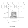
- Load pull is a measurement technique employing microwave impedance tuners 2 , 4 and other microwave test equipment, such as signal sources 1 , test fixtures and DUT 3 and power meters 5 , the whole controlled by a computer 6 ; said computer controlling and communicating with said tuners 2 , 3 and other equipment 1 , 3 and 5 using digital cables 7 , 8 and 9 .
- the tuners are used in order to manipulate the microwave impedance conditions under which the Device Under Test (DUT, or transistor) is tested (see ref.
- tuners allow determining the optimum impedance conditions for designing amplifiers and other microwave components for specific performance targets, such as gain, efficiency, inter-modulation etc.; this document refers hence to “tuners” as being “impedance tuners”, in order to distinct from “tuned receivers (radios)”, commonly referred to as “tuners” because of the included tuning circuits (see ref. 2).
- Impedance tuners comprise, in general, a slotted transmission airline (slabline) 23 , 24 and adjustable reflection probes 22 , FIG. 2 ; the probe 22 is attached to a precision vertical axis 21 which is mounted inside a mobile carriage 28 ; the axis 21 can move the probe 22 vertically 216 towards the center conductor 23 and the carriage 28 can move the probe 22 horizontally 217 parallel to the center conductor 23 of the slabline 24 .
- the vertical movement 216 changes the amplitude of the reflection factor seen at the tuner test port 25 whereas the horizontal movement 217 changes the phase.
- Metallic probes 22 , 30 or “slugs” are typically made in a cubical form 41 with a concave bottom 35 which allows to capture, when approaching the center conductor 32 (see FIG. 11 in ref. 4), the electric field, which is concentrated in the area 36 between the center conductor 32 and the ground planes of the slotted airline (slabline) 31 , FIG. 3 .
- This “field capturing” allows creating controllable high capacitance and reflection factors.
- the critical part is the required high proximity of the probe to the center conductor and the high accuracy of the vertical probe movement ( FIG. 6 ), whereby changes in the vertical probe position 62 of a few micrometers affects the reflection factor (and the VSWR) by a large amount.
- the unmoving segment 93 of the center conductor is a short piece of center conductor, anchored permanently on the connector plate 95 , and much shorter than the moving part 94 of the center conductor.
- the thermal expansion of the free part 94 is larger (typically at least twice as long as in the case of FIG. 10 , since its length is larger, thermal expansion of a rod is proportional to its length), but also that, because of its larger length, the slenderness factor “Length/Diameter” is larger.
- the joining tube 102 is placed in the middle of the center conductor, i.e.
- each free-standing segment is one half as long as the tuner (Length/2), then the slenderness factor will also be half, and, following Euler's formula (see ref. 5), the required force for the center conductor to bend or “buckle” will be four times larger. Therefore the risk of “buckling” under axial force will be four times smaller.
- the center conductor is positioned exactly in the center of the slabline channel, when heated and it bends (deflects) it may either deflect sideways 515 or downwards 514 or both; of course, it may also deflect upwards (not shown), in which case we may have a premature electrical short circuit. In either case the effect is “at best” loss of accuracy or “at worst” an electrical short and damage of the tuner and/or the DUT.
- This invention discloses solutions allowing avoidance of such catastrophic and systemic test problems.
- FIG. 1 depicts Prior Art: a typical automated transistor load pull test system.
- FIG. 2 depicts Prior Art: a front view of an automated slide screw impedance tuner using a single vertical axis and RF probe (slug).
- FIG. 3 depicts Prior Art: cross section of RF probe inside a slotted airline (slabline) approaching the center conductor.
- FIG. 4 depicts Prior Art: a perspective view of relevant dimensions and parameters of the operation of a vertically adjustable RF probe (slug).
- FIGS. 5A , 5 B 1 , 5 B 2 and 5 B 3 depict prior art: FIG. 5A depicts the center conductor deformation due to heating and expansion and FIGS. 5 B 1 to 5 B 3 depict the possible deflection of the center conductor related to tuning probe: FIG. 5 B 1 corresponds to room temperature; FIG. 5 B 2 corresponds to sidewise deflection and short circuit and FIG. 5 B 3 to deflection away from the center conductor and false measurements.
- FIG. 6 depicts prior art: the measured dependence of tuner VSWR from the proximity (distance) of the tuning probe to the center conductor.
- FIG. 7 depicts the frequency response of a tuner probe positioned close to the center conductor in an ideal case 71 and in the case where the center conductor has moved 72 because of heating.
- FIG. 8 depicts the test setup used to calibrate an automatic impedance tuner.
- FIG. 9 depicts prior art: the method used to allow thermal expansion of center conductor in tuners (sliding contact).
- FIG. 10 depicts a segmented center conductor using an expansion ring, allowing the segments to expand linearly under influence of dissipated power and heat.
- FIG. 11 depicts a front view of two segments of thermally expanding center conductor, joined by a conductive ring and associated dimensions.
- FIG. 12 depicts actual tube and rod diameters used to estimate inductive versus capacitive disturbance of the characteristic impedance of the segmented and temperature compensated center conductor.
- FIG. 13 depicts detail of reliable RF contact between the expansion tube and interface rod protrusion.
- FIG. 14 depicts the contact tube sliding over massive protrusions inserted and attached permanently into the adjacent center conductor segments; the tube may have the same or different diameter as the center conductor, depending on the application.
- FIG. 15 depicts the 3D view of the contact tube sliding over the protrusions made as massive pin insertions into the center conductor segments.
- FIG. 16 depicts an embodiment whereby it is the inserting protrusion which is slotted and not the expansion tube.
- the spurious impedance jump is inductive, since the exposed portion of the sliding contact 91 represents a series inductance and creates a higher characteristic impedance (Z 1 ) than the slabline itself (Zo); it is therefore important (a) to reduce this gap 91 and associated impedance jumps as much as possible, especially at high frequencies, where the length of the gap 96 may be critical, relative to the signal wavelength; and (b) to introduce a compensation by creating a parallel capacitive load.
- This second point is possible by making the diameter of the tube 93 larger than the diameter of the center conductor 94 . This has not been disclosed in the prior art ( FIG. 9 ).
- Z(D1) ⁇ Z(Do) ⁇ Z(Do) ⁇ Z(D2) whereby Do is the diameter of the center conductor, D1 is the diameter of the protrusion and D2 is the diameter of the sliding tube.
- the center conductor 120 , 125 is cut short and two interface rods 128 and 129 are attached to center conductor ends tightly (typically using screw inserts) (see also items 1001 and 1002 in FIG. 10 ).
- the inductive behavior of protrusion 121 is compensated by the capacitive behavior of the left half of the tube 127 and the inductive behavior of protrusion 124 is compensated by the capacitive behavior of the right tube half 126 .
- the symmetry plan 123 is arbitrary and can as well be the geometrical center of the tube.
- a further problem of the prior art structure ( FIG. 9 ) is reliability; if the thermal cycle is repeated several times, the silver or gold surface plating of the protrusion and/or the inner wall of the tube are going to wear out and the electrical conductivity is going to change (increase sharply). This depends on the thickness of the plating layer and the tightness of the sliding contact; of course if the whole body of the center conductor would be made of massive silver, brass or copper, excluding massive gold for cost reasons, the wearing out problem would disappear.
- high electrical conductivity is associated with lower mechanical sturdiness, i.e. such long center conductors would be prone to “sag” over time under its own weight.
- the material of choice for long center conductors is steel, which, because of its inherent high electrical resistance, has to be gold or silver plated. In this case the reliability problem of surface wear-out re-surfaces.
- the solution introduced here is to insert two interface rod segments on each side of the sliding tube, on which′ protrusions the tube slides, made of homogenous massive high electrical conductivity material, such as brass, bronze, silver or copper, whereby there is no surface plating to be worn-out. This is shown in FIGS. 10 and 11 .
- the center conductor 105 and 106 is cut short by the sum of the lengths of the inserts 101 and 103 , the tube 102 and the exposed sections of the protrusions 109 and 104 .
- the tube 102 has several slots 100 cut parallel to its axis allowing a pre-bend inward to establish secure sliding contact on the protrusions on both sides.
- RF contacts are extremely critical; they must always be well defined and mechanically repeatable. This is ensured here using the pre-bending of the ends of the tube 102 , which allows the RF contact to take place at the inside surface of the pre-loaded edge of the tube cylinder (see self-explanatory FIG. 13 ):
- the protrusion enters the cavity of the tube; the tube has axial slots 100 , shown in FIG.
- L is the length of the center conductor
- ⁇ L the expansion
- ⁇ is the linear thermal expansion coefficient of the center conductor material (in this case steel ⁇ 45 ppm/° C.)
- ⁇ is the temperature increase in degrees.
- the larger gap required, in the prior art configuration, when the sliding contact is placed close to the connector ( FIG. 9 ) is causing a larger parasitic inductance and inferior RF performance.
- the connecting tube 102 shall be manufactured from well conducting and elastic material, preferably spring-Bronze or Beryllium Copper (BeCu), because of its good electrical conductivity and strong spring-metal behavior, which allow long lasting and reliable DC and RF sliding contact between the tube's 102 inner walls and the protrusions 104 , which move into and out of the tube; the protrusions 104 , 109 are concentric with and machined (carved out) from the body of the interface rods 101 , 103 .
- the gaps are dimensioned to allow for maximum thermal expansion 105 , 106 , caused by the DC and RF power, the tuner is expected to handle.
- Slots 100 cut into the mantle of the connecting tube 102 provide for and enhance the spring mechanism for the sliding contact. As shown in FIG. 10 , each segment 101 , 103 will expand 105 , 106 only towards the connecting tube 102 , since the connectors 107 and 108 are unmovable obstacles (borders).
- each segment can expand a certain amount 113 and 117 before hitting the connecting tube walls 114 .
- the gap 115 left between the tips of the protrusions 116 , shall be larger than the sum of the two gaps 113 and 117 between the cores 118 , 112 of the center conductor and the edges of the tube 114 .
- FIG. 14 An alternative, simplified embodiment, fulfilling the same requirements as hitherto disclosed in this invention is shown in FIG. 14 .
- the interface rods 112 and 118 are replaced by center pins 141 and 142 , which are made of massive non-plated highly conductive metal, and are inserted and permanently attached to the center conductor segments 140 and 143 , while sliding on the central tube 144 (and making good RF contact, as shown in FIG. 13 ) to allow for thermal expansion and contraction of the center conductor.
- FIG. 16 depicts an embodiment whereby it is the inserting protrusion which is slotted making contact from inside and not the expansion tube.
- This configuration has the reliability advantage that the spread of the protrusion is going to maintain its shape and therefore the sliding RF contact, even if slightly compressed, which is not the case with the embodiment of FIGS. 10, 11, 13 and 15 .
- the tuner is calibrated using a network analyzer 80 , VNA and a control computer 82 in room temperature; the tuner is connected using RF cables 85 to the VNA ports and using digital cables 88 to the computer 82 ; the computer controls also the VNA using different digital cables and communication protocol 81 ; the probes 84 are positioned horizontally and vertically inside the slabline 89 in order to generate desired reflection factors within the tuning range of said tuner ( FIG. 8 ); the collected s-parameter data from the VNA are saved in tuner calibration files.
- This generic tuner calibration method is used abundantly in the specific art and is hereby applied to the high reliability high power tuner as well with a higher probability of eliminating shorts and systemic measurement errors at high power operation.
Landscapes
- Engineering & Computer Science (AREA)
- Computer Hardware Design (AREA)
- Microelectronics & Electronic Packaging (AREA)
- Control Of Motors That Do Not Use Commutators (AREA)
Abstract
Description
- 1. “Load Pull for Power Devices” [online], [retrieved on Mar. 14, 2017], <URL: https://www.microwaves101.com/encyclopedias/load-pull-for-power-devices>.
- 2. “Computer Controlled Microwave Tuner—CCMT”,
Product Note 41, Focus Microwaves, January 1998. - 3. “Standing wave ratio, VSWR”, [online], [retrieved on Mar. 2, 2017], <URL: https://en.wikipedia.org/wiki/Standing_wave_ratio>.
- 4. Tsironis, U.S. Pat. No. 6,674,293, “Adaptable pre-matched tuner system and method”
- 5. Euler formula, “Buckling” [online], [retrieved on Mar. 11, 2016], <URL:https://en.wikipedia.org/wiki/Buckling>.
Claims (10)
Priority Applications (1)
| Application Number | Priority Date | Filing Date | Title |
|---|---|---|---|
| US15/458,424 US9866203B1 (en) | 2016-03-21 | 2017-03-14 | High reliability power tuners |
Applications Claiming Priority (2)
| Application Number | Priority Date | Filing Date | Title |
|---|---|---|---|
| US201662311130P | 2016-03-21 | 2016-03-21 | |
| US15/458,424 US9866203B1 (en) | 2016-03-21 | 2017-03-14 | High reliability power tuners |
Publications (1)
| Publication Number | Publication Date |
|---|---|
| US9866203B1 true US9866203B1 (en) | 2018-01-09 |
Family
ID=60813470
Family Applications (1)
| Application Number | Title | Priority Date | Filing Date |
|---|---|---|---|
| US15/458,424 Expired - Fee Related US9866203B1 (en) | 2016-03-21 | 2017-03-14 | High reliability power tuners |
Country Status (1)
| Country | Link |
|---|---|
| US (1) | US9866203B1 (en) |
Cited By (5)
| Publication number | Priority date | Publication date | Assignee | Title |
|---|---|---|---|---|
| US10930991B1 (en) * | 2019-09-05 | 2021-02-23 | The Government Of The United States Of America, As Represented By The Secretary Of The Navy | Method and/or apparatus for frictionless wideband high-power radio-frequency power transmission across a freely moving interface |
| US11119140B1 (en) | 2017-08-31 | 2021-09-14 | Christos Tsironis | Impedance pattern generation for noise parameter measurement system |
| US11480610B1 (en) | 2020-12-01 | 2022-10-25 | Christos Tsironis | Load pull pattern generation |
| US11742833B1 (en) | 2020-04-15 | 2023-08-29 | Christos Tsironis | Temperature controlled high power tuner |
| US12519458B1 (en) * | 2023-11-30 | 2026-01-06 | Christos Tsironis | Low frequency load pull tuner using dielectric filled spiral airline |
Citations (3)
| Publication number | Priority date | Publication date | Assignee | Title |
|---|---|---|---|---|
| US6674293B1 (en) | 2000-03-01 | 2004-01-06 | Christos Tsironis | Adaptable pre-matched tuner system and method |
| US8466758B1 (en) * | 2011-07-12 | 2013-06-18 | Christos Tsironis | Impedance tuner with integrated bias network |
| US9666928B1 (en) * | 2015-10-30 | 2017-05-30 | Christos Tsironis | High power slide screw tuners |
-
2017
- 2017-03-14 US US15/458,424 patent/US9866203B1/en not_active Expired - Fee Related
Patent Citations (3)
| Publication number | Priority date | Publication date | Assignee | Title |
|---|---|---|---|---|
| US6674293B1 (en) | 2000-03-01 | 2004-01-06 | Christos Tsironis | Adaptable pre-matched tuner system and method |
| US8466758B1 (en) * | 2011-07-12 | 2013-06-18 | Christos Tsironis | Impedance tuner with integrated bias network |
| US9666928B1 (en) * | 2015-10-30 | 2017-05-30 | Christos Tsironis | High power slide screw tuners |
Non-Patent Citations (6)
| Title |
|---|
| "Computer Controlled Microwave Tuner-CCMT", Product Note 41, Focus Microwaves, Jan. 1998. |
| "Load Pull for Power Devices" [online], [retrieved on Mar. 14, 2017], <URL: https://www.microwaves101.com/encyclopedias/load-pull-for-power-devices>. |
| "Standing wave ratio, VSWR", [online], [retrieved on Mar. 2, 2017], <URL: https://en.wikipedia.org/wiki/Standing-wave-ratio>. |
| "Computer Controlled Microwave Tuner—CCMT", Product Note 41, Focus Microwaves, Jan. 1998. |
| "Standing wave ratio, VSWR", [online], [retrieved on Mar. 2, 2017], <URL: https://en.wikipedia.org/wiki/Standing—wave—ratio>. |
| Euler formula, "Buckling" [online], [retrieved on Mar. 11, 2016], <URL:https://en.wikipedia.org/wiki/Buckling>. |
Cited By (5)
| Publication number | Priority date | Publication date | Assignee | Title |
|---|---|---|---|---|
| US11119140B1 (en) | 2017-08-31 | 2021-09-14 | Christos Tsironis | Impedance pattern generation for noise parameter measurement system |
| US10930991B1 (en) * | 2019-09-05 | 2021-02-23 | The Government Of The United States Of America, As Represented By The Secretary Of The Navy | Method and/or apparatus for frictionless wideband high-power radio-frequency power transmission across a freely moving interface |
| US11742833B1 (en) | 2020-04-15 | 2023-08-29 | Christos Tsironis | Temperature controlled high power tuner |
| US11480610B1 (en) | 2020-12-01 | 2022-10-25 | Christos Tsironis | Load pull pattern generation |
| US12519458B1 (en) * | 2023-11-30 | 2026-01-06 | Christos Tsironis | Low frequency load pull tuner using dielectric filled spiral airline |
Similar Documents
| Publication | Publication Date | Title |
|---|---|---|
| US9866203B1 (en) | High reliability power tuners | |
| US9666928B1 (en) | High power slide screw tuners | |
| US8416030B2 (en) | Impedance tuner systems and probes | |
| US10686239B1 (en) | Slide screw tuners with offset tuning probes and method | |
| US10700402B1 (en) | Compact millimeter-wave tuner | |
| US6515465B2 (en) | Method and apparatus for measuring harmonic load-pull for frequency multiplication | |
| US8933707B1 (en) | Waveguide impedance tuners with planarity adjustment for wafer probing | |
| US9252471B1 (en) | Wideband attenuation and phase controller | |
| US9899984B1 (en) | Compact multi-carriage impedance tuner and method | |
| US11233307B1 (en) | Directional wire coupler for waveguide tuners and method | |
| US10693437B1 (en) | High gamma on-wafer load pull test system | |
| KR20220106916A (en) | Hybrid shielding sockets with impedance tuning for integrated circuit device test tooling | |
| US9041498B1 (en) | Mechanically short multi-carriage tuner | |
| US11156656B1 (en) | Waveguide slide screw tuner with rotating disc probes | |
| Huang et al. | De-embedding method to accurately measure high-frequency impedance of an O-shape spring contact | |
| US9716303B1 (en) | Low cost probes for slide screw tuners | |
| US8362787B1 (en) | Harmonic rejection tuner with adjustable short circuited resonators | |
| US10725092B1 (en) | Pre-matched coaxial transistor test fixture | |
| Koenen et al. | A self-aligning cylindrical sliding short plunger for millimeter-wave rectangular waveguides and its application in a reflection-type phase shifter | |
| US10971791B1 (en) | Transmission line for high power tuners | |
| US12199691B2 (en) | Waveguide component for high frequency testing | |
| US10591511B1 (en) | Frequency adjustable pre-matching coaxial transistor test fixture | |
| US10734697B1 (en) | Coaxial adjustable wave probe | |
| US8461946B1 (en) | Impedance tuners with mechanical stop | |
| US2437889A (en) | High-frequency tuning device |
Legal Events
| Date | Code | Title | Description |
|---|---|---|---|
| AS | Assignment |
Owner name: FOCUSMW IP. INC., CANADA Free format text: ASSIGNMENT OF ASSIGNORS INTEREST;ASSIGNOR:TSIRONIS, CHRISTOS;REEL/FRAME:041571/0429 Effective date: 20170314 |
|
| STCF | Information on status: patent grant |
Free format text: PATENTED CASE |
|
| AS | Assignment |
Owner name: TSIRONIS, CHRISTOS, CANADA Free format text: ASSIGNMENT OF ASSIGNORS INTEREST;ASSIGNOR:FOCUSMW IP. INC.;REEL/FRAME:048449/0136 Effective date: 20190227 |
|
| MAFP | Maintenance fee payment |
Free format text: PAYMENT OF MAINTENANCE FEE, 4TH YR, SMALL ENTITY (ORIGINAL EVENT CODE: M2551); ENTITY STATUS OF PATENT OWNER: SMALL ENTITY Year of fee payment: 4 |
|
| FEPP | Fee payment procedure |
Free format text: MAINTENANCE FEE REMINDER MAILED (ORIGINAL EVENT CODE: REM.); ENTITY STATUS OF PATENT OWNER: SMALL ENTITY |
|
| AS | Assignment |
Owner name: FOCUSMW IP. INC., CANADA Free format text: ASSIGNMENT OF ASSIGNORS INTEREST;ASSIGNOR:TSIRONIS, CHRISTOS;REEL/FRAME:073588/0660 Effective date: 20251112 |