US9865356B2 - Circuit and method for reading a memory cell of a non-volatile memory device - Google Patents
Circuit and method for reading a memory cell of a non-volatile memory device Download PDFInfo
- Publication number
- US9865356B2 US9865356B2 US15/275,362 US201615275362A US9865356B2 US 9865356 B2 US9865356 B2 US 9865356B2 US 201615275362 A US201615275362 A US 201615275362A US 9865356 B2 US9865356 B2 US 9865356B2
- Authority
- US
- United States
- Prior art keywords
- node
- global
- coupled
- local
- bitline
- Prior art date
- Legal status (The legal status is an assumption and is not a legal conclusion. Google has not performed a legal analysis and makes no representation as to the accuracy of the status listed.)
- Active
Links
Images


Classifications
-
- G—PHYSICS
- G11—INFORMATION STORAGE
- G11C—STATIC STORES
- G11C16/00—Erasable programmable read-only memories
- G11C16/02—Erasable programmable read-only memories electrically programmable
- G11C16/06—Auxiliary circuits, e.g. for writing into memory
- G11C16/26—Sensing or reading circuits; Data output circuits
-
- G—PHYSICS
- G11—INFORMATION STORAGE
- G11C—STATIC STORES
- G11C7/00—Arrangements for writing information into, or reading information out from, a digital store
- G11C7/12—Bit line control circuits, e.g. drivers, boosters, pull-up circuits, pull-down circuits, precharging circuits, equalising circuits, for bit lines
-
- G—PHYSICS
- G11—INFORMATION STORAGE
- G11C—STATIC STORES
- G11C16/00—Erasable programmable read-only memories
- G11C16/02—Erasable programmable read-only memories electrically programmable
- G11C16/04—Erasable programmable read-only memories electrically programmable using variable threshold transistors, e.g. FAMOS
- G11C16/0408—Erasable programmable read-only memories electrically programmable using variable threshold transistors, e.g. FAMOS comprising cells containing floating gate transistors
-
- G—PHYSICS
- G11—INFORMATION STORAGE
- G11C—STATIC STORES
- G11C16/00—Erasable programmable read-only memories
- G11C16/02—Erasable programmable read-only memories electrically programmable
- G11C16/06—Auxiliary circuits, e.g. for writing into memory
- G11C16/08—Address circuits; Decoders; Word-line control circuits
-
- G—PHYSICS
- G11—INFORMATION STORAGE
- G11C—STATIC STORES
- G11C16/00—Erasable programmable read-only memories
- G11C16/02—Erasable programmable read-only memories electrically programmable
- G11C16/06—Auxiliary circuits, e.g. for writing into memory
- G11C16/24—Bit-line control circuits
-
- G—PHYSICS
- G11—INFORMATION STORAGE
- G11C—STATIC STORES
- G11C16/00—Erasable programmable read-only memories
- G11C16/02—Erasable programmable read-only memories electrically programmable
- G11C16/06—Auxiliary circuits, e.g. for writing into memory
- G11C16/26—Sensing or reading circuits; Data output circuits
- G11C16/28—Sensing or reading circuits; Data output circuits using differential sensing or reference cells, e.g. dummy cells
-
- G—PHYSICS
- G11—INFORMATION STORAGE
- G11C—STATIC STORES
- G11C7/00—Arrangements for writing information into, or reading information out from, a digital store
- G11C7/18—Bit line organisation; Bit line lay-out
-
- G—PHYSICS
- G11—INFORMATION STORAGE
- G11C—STATIC STORES
- G11C2207/00—Indexing scheme relating to arrangements for writing information into, or reading information out from, a digital store
- G11C2207/002—Isolation gates, i.e. gates coupling bit lines to the sense amplifier
-
- G—PHYSICS
- G11—INFORMATION STORAGE
- G11C—STATIC STORES
- G11C2207/00—Indexing scheme relating to arrangements for writing information into, or reading information out from, a digital store
- G11C2207/12—Equalization of bit lines
Definitions
- the present invention relates to a circuit and a method for reading a memory cell of a non-volatile memory device, for example of a floating-gate flash type.
- the reading circuit and method do not envisage the use of reference circuit elements or structures for reading the datum stored in the memory cell.
- a non-volatile memory device designated by 1 , for example of a flash type, generally comprises a memory array 2 made up of a plurality of memory cells 3 , arranged in rows (usually defined as wordlines, WL), and columns (usually defined as bitlines, BL).
- Each memory cell 3 is constituted by a storage element, for example formed by a floating-gate transistor in flash memories, with gate terminal designed to be coupled to a respective wordline WL, a first conduction terminal designed to be coupled to a respective bitline BL and a second conduction terminal connected to a reference potential (for example ground, gnd).
- a reference potential for example ground, gnd
- a reading circuit 4 (represented schematically in FIG. 1 ) enables selection, on the basis of address signals received at the input (generated in a known manner and designated in general by AS), of the memory cells 3 , and in particular of the corresponding wordlines WL and bitlines BL each time addressed, enabling biasing thereof at appropriate voltage and current values during the operations of reading of the data stored.
- the reading circuit 4 provides in particular a reading path, which is designed to create a conductive path between the bitlines BL of the memory array 2 each time selected and a sense-amplifier stage, of a differential type, designed to compare the current circulating in the addressed (i.e., activated) memory cell 3 , which receives an appropriate biasing voltage on the respective gate terminal, with a reference current, in order to determine the value of the datum stored and consequently generate a digital reading signal, indicative of the datum stored.
- a reading path which is designed to create a conductive path between the bitlines BL of the memory array 2 each time selected and a sense-amplifier stage, of a differential type, designed to compare the current circulating in the addressed (i.e., activated) memory cell 3 , which receives an appropriate biasing voltage on the respective gate terminal, with a reference current, in order to determine the value of the datum stored and consequently generate a digital reading signal, indicative of the datum stored.
- a reading circuit 4 of a known type, thus envisages in general, as illustrated schematically in FIG. 2 , a sense-amplifier stage, designated by 6 , having: a first differential input 6 a , coupled to a memory cell 3 (to the gate terminal of which an appropriate row-biasing voltage V WL is supplied), from which it receives a cell reading current I cell , the value of which is a function of the datum stored; a second differential input 6 b , coupled to a reference circuit element 8 , from which it receives a reference current I ref ; and an output 6 c that supplies a digital output signal S out , the value of which is a function of the comparison between the cell reading current I cell and the reference current I ref , and is indicative of the value of the datum stored in the memory cell 3 , activated for reading the same datum.
- the aforesaid reference circuit element 8 may for example be: a reference cell 8 a , which is structurally the same as the memory cell 3 that is to be read and has electrical characteristics controlled and known beforehand (for supplying a known value of the reference current I ref ); or else a reference-current generator 8 b , designed to generate the same reference current I ref , of a desired value.
- the reading operation of the datum stored in the memory cell 3 thus envisages detection of the cell reading current I cell and its comparison with the reference current I ref , in order to generate, via the sense-amplifier stage 6 , the digital output signal S out .
- the digital output signal S out may have a high logic value, ‘1’; whereas the digital output signal S out may have a low logic value, ‘0’, in the opposite case, where, that is, the cell reading current I cell is lower than the reference current I ref .
- the present Applicant has realized that the solutions of a known type for carrying out reading of the data stored in the memory cells of non-volatile memory devices may not be compatible with the requirements of size reduction (the so-called “scaling down”) of memory cells, and of simultaneous increase in electrical performance (in particular, in terms of increase in reading speed, or likewise of reduction of the access time and consumption), envisaged by technological progress.
- Embodiments of the present invention provide a solution for reading a memory cell of a non-volatile memory device, with improved electrical performance and reduced area occupation.
- a circuit for reading a memory cell of a non-volatile memory device and a corresponding reading method are provided, as defined in the annexed claims.
- FIG. 1 shows a general block diagram of a non-volatile memory device, of a known type
- FIG. 2 shows a general block diagram of a reading circuit in the non-volatile memory device of FIG. 1 , which is also of a known type;
- FIG. 3 shows a circuit for reading a memory cell, according to an embodiment of the present invention
- FIGS. 4, 5, 6 a - 6 c , and 7 a - 7 c show the reading circuit of FIG. 3 , with voltage values indicated on respective nodes, in given operating conditions, referring to an operation of reading of a datum stored in the memory cell;
- FIGS. 8, 9 a - 9 b show plots of electrical quantities in the reading circuit of FIG. 3 .
- a particular aspect of the present solution envisages, as will be described in detail, first with reference to FIG. 3 , elimination, for the reading operations, of a reference circuit element (whether this is a reference memory cell, or a reference-current generator, or any other element purposely provided for generating a reference electrical quantity or comparison electrical quantity).
- a reference circuit element whether this is a reference memory cell, or a reference-current generator, or any other element purposely provided for generating a reference electrical quantity or comparison electrical quantity.
- the present solution envisages execution of an operation of comparison between electrical quantities associated to two bitlines of the memory array 2 , and in particular the bitline BL to which the memory cell 3 belongs, activated for reading of the datum stored, and a different bitline BL′, for example the (physically or logically) adjacent bitline in the same memory array 2 .
- a reading circuit designated by 20 , which implements a hierarchical column decoding with two decoding levels, local and global, in a non-volatile memory device (for example, the non-volatile memory device 1 of FIG. 1 , of a flash type with floating-gate memory cells).
- a non-volatile memory device for example, the non-volatile memory device 1 of FIG. 1 , of a flash type with floating-gate memory cells.
- the reading circuit 20 (of which only the elements required for the description of the present solution are shown) comprises a control unit 21 (represented schematically), and moreover a circuit branch 22 , 22 ′ for each of the bitlines of the memory array 2 .
- a control unit 21 represented schematically
- a circuit branch 22 , 22 ′ for each of the bitlines of the memory array 2 .
- FIG. 3 as in the subsequent figures, reference is made only to two adjacent bitlines BL and BL′ of the memory array 2 .
- circuit branch 22 will be described, altogether similar considerations evidently applying also to the circuit branch 22 ′ (as on the other hand is evident from an examination of the aforesaid FIG. 3 ).
- the circuit branch 22 comprises a number of elements.
- At least one local decoding transistor 23 in the example of an NMOS type, has a first conduction terminal connected to a local node N l , which is coupled to a local bitline BL l , and which is in turn physically connected to the bitline BL and to the memory cell 3 activated for reading (here represented schematically as a generator of the cell reading current I cell ).
- a second conduction terminal is connected to a global node N g , coupled to a global bitline BL g (also referred to as “main bitline”), which represents a level of decoding hierarchically higher than the local bitline BL l .
- a control terminal of the transistor 23 receives a local decoding signal VY 0 from the control unit 21 of the non-volatile memory device 1 .
- the circuit branch 22 also comprises at least one global decoding transistor 25 , in the example of an NMOS type, having a first conduction terminal connected to the global node N g , a second conduction terminal connected to an internal node N i , and a control terminal receiving a global decoding signal VYN from the control unit 21 .
- the circuit branch 22 also comprises at least one protection transistor 26 , in the example of an NMOS type, having a first conduction terminal connected to the internal node N i , a second conduction terminal connected to a comparison node N c , on which a comparison voltage V c is present, and a control terminal receiving a biasing signal V b .
- the circuit branch 22 also comprises an enabling transistor 28 , in the example of a PMOS type, having a first conduction terminal connected to the comparison node N c , a second conduction terminal connected to a supply terminal, which receives a supply voltage V DD for supplying the memory device 1 , and a control terminal, which receives an enabling signal EN.
- an enabling transistor 28 in the example of a PMOS type, having a first conduction terminal connected to the comparison node N c , a second conduction terminal connected to a supply terminal, which receives a supply voltage V DD for supplying the memory device 1 , and a control terminal, which receives an enabling signal EN.
- the local column decoding, for selection and biasing of the local bitline BL l could be implemented by further local decoding transistors (here not illustrated), and likewise the global column decoding, for selection and biasing of the global bitline BL g , could be implemented by further global decoding transistors (not illustrated here, either), depending on the size of the memory array 2 and the decoding requirements.
- the local decoding transistor 23 ′ of the circuit branch 22 ′ receives on the control terminal a respective local decoding signal, designated by VY 1 , whereas the global decoding transistor 25 ′ receives the same global decoding signal VYN of the global decoding transistor 25 (typically, a number of local bitlines, for example four, may in fact be selectively coupled to a same global bitline, which consequently selects and biases a “sector” of the memory array 2 constituted by the memory cells 3 connected to these local bitlines).
- the protection transistor 26 ′ of the circuit branch 22 ′ receives the same biasing signal V b as the protection transistor 26 , whereas the enabling transistor 28 ′ receives a respective enabling signal EN′.
- the aforesaid protection transistors 26 , 26 ′ have a cascode function; i.e., the value of the biasing voltage V b is such as to set a maximum value allowed for the voltages of the underlying internal nodes N i , N i ′, preventing any possible stresses and damage during reading.
- the enabling transistors 28 , 28 ′ have the function of enabling pre-charging of the nodes of the circuit branches 22 , 22 ′ and of the parasitic capacitances associated to the corresponding bitlines BL, BL′.
- a first parasitic capacitor 30 (represented with a dashed line) is coupled between the local node N l , associated to the local bitline BL l , and the ground reference gnd of the reading circuit 20 .
- a second parasitic capacitor 32 (which is also represented with a dashed line) is coupled between the global node N g , associated to the global bitline BL g , and the same ground reference gnd.
- the capacitance C g of the second parasitic capacitor 32 i.e., the parasitic capacitance associated to the global bitline BL g
- the capacitance C l of the first parasitic capacitor 30 is much greater (for example, at least by one order of magnitude) than the capacitance C l of the first parasitic capacitor 30 , i.e., the parasitic capacitance associated to the local bitline BL l .
- the values of the capacitances C l and C g associated to the circuit branch 22 are further substantially equal to the values of the corresponding capacitances C l ′ and C g ′ associated to the circuit branch 22 ′.
- the ratios of the resistances associated to the global bitline BL g and the local bitline BL l are instead typically opposite, the local bitline BL l being in fact normally more resistive than the global bitline BL g .
- the circuit branch 22 further comprises a further output capacitor 34 , which may be parasitic or be physically present in the circuit, between the comparison node N c and the ground reference gnd.
- capacitance C o of this output capacitor 34 is much lower than the capacitance C g associated to the global bitline BL g of the same circuit branch 22 ; furthermore, the value of capacitance C o of the output capacitor 34 of the circuit branch 22 is substantially equal to the value of capacitance C o ′ of the output capacitor 34 ′ of the circuit branch 22 ′.
- the reading circuit 20 further comprises a sense-amplifier stage 36 , of a differential type, having a first input 36 a and a second input 36 b , connected, respectively, to the comparison node N c of the circuit branch 22 and to the comparison node N c ′ of the circuit branch 22 ′, which consequently receive the respective comparison voltages V c , V c ′, and an output 36 c supplying a digital output signal, once again designated by S out , having a logic value ‘1’ or ‘0’, indicative of the value of the datum stored in the memory cell 3 activated for reading.
- a sense-amplifier stage 36 of a differential type, having a first input 36 a and a second input 36 b , connected, respectively, to the comparison node N c of the circuit branch 22 and to the comparison node N c ′ of the circuit branch 22 ′, which consequently receive the respective comparison voltages V c , V c ′, and an output 36 c supplying a digital output
- the reading circuit 20 further comprises a coupling stage formed by a first coupling transistor 40 , in the example of an NMOS type, which is connected between the global nodes N g and N g ′ of the circuit branches 22 , 22 ′ and has a control terminal receiving an equalization signal EQ; and a second coupling transistor 41 , which in the example is also of an NMOS type, is connected between the internal nodes N i , N i ′ of the circuit branches 22 , 22 ′, and has a respective control terminal receiving the same equalization signal EQ.
- the first and second coupling transistors 40 , 41 have the function of equalizing the nodes on their terminals, referred to the circuit branches 22 , 22 ′ of the adjacent bitlines BL, BL′, guaranteeing that the corresponding voltage values are substantially equal, in given operating conditions.
- a first operating step for preparation of the voltages at the nodes, and in particular for pre-charging of the parasitic capacitors 30 , 32 of the circuit branch 22 ;
- a third operating step for unbalancing, on the basis of the value of the datum stored in the memory cell 3 , of the voltages on the global nodes N g and N g ′ of the circuit branches 22 , 22 ′ and consequently of the comparison voltages V c , V c ′ on the comparison nodes N c and N c ′, and of comparison of the same voltages V c , V c ′ for generation of the digital output signal S out indicative of the value of the stored datum.
- the first operating step envisages the following conditions:
- local decoding signal VY 1 low (local decoding transistor 23 ′ off; for this reason, local decoding transistor 23 ′ is not represented in FIG. 4 );
- equalization signal EQ low first and second coupling transistors 40 , 41 off
- the memory cell 3 is, in this step, still off or deactivated (in a way not illustrated, the corresponding wordline WL has not yet been addressed and/or biased at the value required by the reading operation).
- the local decoding signal VY 0 is switched to the low value (local decoding transistor 23 is off);
- the enabling signal EN is switched to the high value (enabling transistor 28 is off).
- the equalization signal EQ is switched to the high value (coupling transistors 40 , 41 are on).
- Switching-on of the coupling transistors 40 , 41 causes a process of equalization between the adjacent bitlines BL, BL′, and of charge division between the corresponding parasitic capacitors 32 , 32 ′.
- the voltages on the global nodes N g , N g ′ substantially reach a same value, (V dd ⁇ V b )/2, i.e., a value lower, as regards the circuit branch 22 , than the value assumed during the previous, pre-charging, step.
- Switching-off of the enabling transistors 28 , 28 ′ causes the voltages on the comparison nodes N c , N c ′ to go to the same value of the internal nodes N i , N i ′, which are in turn substantially equal to the aforesaid voltages on the global nodes N g , N g ′.
- the voltage on the local node N l of the circuit branch 22 associated to the memory cell 3 to be read, remains at the initial value V dd ⁇ V b (due to switching-off of the local decoding transistor 23 and the floating condition of the same local node N l ).
- the wordline WL associated to the memory cell 3 is in the meantime addressed and appropriately biased (in a per se known manner), by the control unit 21 , in such a way that the cell reading current I cell flows in the memory cell 3 , as a function of the datum stored.
- the row-biasing voltage V WL is supplied to the gate terminal of the memory cell.
- the third operating step then follows, where two different operating conditions may arise according to whether the datum stored in the memory cell 3 to be read is a logic ‘1’ or a logic ‘0’.
- the equalization signal EQ again goes low, for turning off the coupling transistors 40 , 41 ; the wordline WL has reached the correct biasing value.
- the cell current I cell acquired from the memory cell 3 has discharged the local node N l , bringing about a reduction of the voltage value thereof with respect to the value assumed in the previous step (i.e., V dd ⁇ V b ), possibly reaching a zero value.
- the local decoding signal VY 0 is switched again to the high value, by switching on the local decoding transistor 23 , which thus connects the local node N l to the global node N g .
- the resulting charge division between the first and second parasitic capacitors 30 , 32 leads to a consequent reduction of the voltage value on the global node N g .
- the sum of the amount of charge stored in the parasitic capacitors 30 , 32 remains constant following capacitive division.
- This final value V f is consequently lower than the initial voltage of the global node N g , equal to (V dd ⁇ V b )/2.
- the final value V f is generally still lower than the value indicated.
- the local decoding signal VY 0 is switched again to the low value, thus switching off the local decoding transistor 23 , for “freezing” the values of the voltages on the local and global nodes N l , N g (stored in the corresponding first and second parasitic capacitors 30 , 32 ).
- the digital output signal S out has in this case a first logic value, for example high, indicating reading of a logic ‘1’ in the memory cell 3 .
- the time allowed to the memory cell 3 during reading to discharge the local node N l in the case of cell at ‘1’ has to be sufficient for providing a significant variation of voltage, or likewise a significant variation of charge so that in the subsequent capacitive division a significant reduction in the voltage of the global node N g and of the comparison node N c occurs, and a sufficient voltage difference is thus present that may be detected by the differential sense-amplifier structure.
- the local decoding signal VY 0 is then switched to the high value, as described in regard to the previous case.
- the voltage value of the local node N l is higher than the voltage value of the global node N g , which in fact initially is equal to (V dd ⁇ V b )/2.
- the resulting charge division between the first and second parasitic capacitors 30 , 32 thus leads to an increase in the value of the voltage on the same global node N g .
- This final value V f is in this case consequently higher than the initial voltage on the global node N g , equal to (V dd ⁇ V b )/2.
- the local decoding signal VY 0 is again switched to the low value, thus switching off the local decoding transistor 23 for “freezing” the values of the voltages on the local and global nodes N l , N g .
- the digital output signal S out consequently has in this case a second logic value, for example low, indicating reading of a logic ‘0’ in the memory cell 3 .
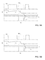
- FIG. 8 shows, with reference to the operating steps described previously (referred to as “step 1”, “step 2”, and “step 3”), the waveforms of: the local decoding signals VY 0 , of the adjacent circuit branches 22 , 22 ′; the row-biasing voltage V WL associated to the wordlines WL of the memory cell 3 activated for reading; the enabling signal EN; and the equalization signal EQ.
- FIG. 9 a shows the plots of the comparison voltages V c , V c ′ of the adjacent circuit branches 22 , 22 ′ in the case of reading of a stored datum having value ‘1’.
- V c the comparison voltage
- FIG. 9 b shows the plots of the comparison voltages V c , V c ′ of the adjacent circuit branches 22 , 22 ′ in the case of reading of a stored datum having a value ‘0’; in particular, it is pointed out in this case that, following upon switching of the local decoding signal VY 0 to the high state, in this case the local node N l is at a voltage value higher than the global node N g of the same circuit branch, with the final result that the comparison voltage V c is higher than the comparison voltage V c ′, following upon charge division.
- the present solution thus envisages exploitation of the hierarchical configuration of column decoding, provided with global and local decoding, which intrinsically offers two capacitances on which it is possible to implement the mechanism of charge division for detection of the datum stored.
- the parasitic capacitances C l and C g associated to the local and global bitlines BL l , BL g are exploited, with the parasitic capacitance C l associated to the local bitline BL l that is lower (for example, by one order of magnitude) than the parasitic capacitance C g associated to the global bitline BL g .
- the present solution envisages exploitation of the aforesaid mechanism of charge division to cause, in the circuit branch 22 , the capacitance C g associated to the global bitline BL g , which determines the comparison voltage V c seen by the sense-amplifier stage 36 , to be either discharged or charged by the capacitance C l of the local bitline BL l , according to whether the datum stored in the memory cell 3 is a ‘1’ or a ‘0’.
- the capacitance C l of the local bitline BL l discharges and, once connected to the global bitline BL g , also the global bitline BL g discharges.
- the capacitance C l is at a voltage value higher than that of the capacitance C g , it will be the capacitance C l that transfers charge onto the capacitance of the global bitline BL g , leading to a rise in voltage.
- the ‘0’ and ‘1’ logic values ideally represent, as regards ‘0’ the total absence of current, such as not to move the drain node of the memory cell, i.e., an open circuit; and as regards ‘1’, the dual condition, i.e., a short circuit such as to bring the drain of the memory cell to ground.
- the worst values are extreme values that may lead to confusion between the two logic values, thus, a cell at ‘0’ that, however, absorbs a non-zero current or a cell at ‘1’ that absorbs less current than what is expected, and generally have a value that depends upon the sensitivity of the reading circuit.
- the operation of equalization between the bitlines BL, BL′ advantageously enables exploitation of the bitline BL′ adjacent to the one associated to the memory cell 3 activated for reading, which thus has substantially the same values of parasitic capacitance, acting on two structures that may be deemed identical for fixing the aforesaid initial voltage value V gi .
- the comparison node N c ′ of the bitline BL′ does not substantially modify its own voltage value with respect to the initial pre-charging value, whereas the comparison node N c of the bitline BL, thanks to the capacitive division, modifies its own voltage value, which becomes higher or lower according to the datum to be read.
- the resulting memory device 1 has smaller dimensions and lower electrical consumption as compared to traditional solutions.
- the reading speed is further increased.
- the bitlines BL of a first half are thus, in one step, the ones read and, in the subsequent step, operate as comparison (i.e., as bitlines BL′, according to what has been described previously) for reading the bitlines of the other half.
- non-volatile memory devices of an embedded or stand-alone type
- EPROMs e.g. EPROMs
- EEPROMs e.g. EPROMs
- PCMs Phase-Change Memories
- the presence of two distinct nodes in the decoding column is sufficient (i.e., the nodes previously referred to as the local node N l and the global node N g ), associated to which are different values of capacitance, for implementation of the strategies of charge division described.
- purposely provided charge-division capacitors may be inserted, electrically connected to the same nodes, in order to implement the solution described.
- a different embodiment may envisage the presence of a single coupling transistor between the adjacent bitlines BL, BL′, for example the coupling transistor 40 referred to previously (even though in general, the solution with two coupling transistors 40 , 41 may offer a greater guarantee of proper operation and correct reading of the datum stored).
Landscapes
- Engineering & Computer Science (AREA)
- Microelectronics & Electronic Packaging (AREA)
- Read Only Memory (AREA)
- Dram (AREA)
Abstract
Description
Q(C l)1 =C l ·V(C l)1
where V(Cl)1 is assumed equal to 0, on the hypothesis that the
Q(C g)1 =C g ·V(C g)1
where V(Cg)1 is equal to (Vdd−Vb)/2, on the basis of what has been discussed previously.
Q(C l)2 =C l ·V(C l)2
where V(Cl)2 is a final value Vf.
Q(C g)2 =C g ·V(C g)2
where V(Cg)2 is equal to the same final value Vf, by virtue of the process of charge division.
Q(C l)1 +Q(C g)1 =Q(C l)2 +Q(C g)2
0+10C l·(V dd −V b)/2=C l ·V f+10C l ·V f
whence
V f=5/11·(V dd −V b)=0.45·(V dd −V b)
Q(C l)1 =C l ·V(C l)1
where V(Cl)1 is in this case equal to Vdd−Vb.
Q(C g)1 =C g ·V(C g)1
where V(Cg)1 is equal to (Vdd−Vb)/2.
Q(C l)2 =C l ·V(C l)2
where V(Cl)2 is a final value Vf.
Q(C g)2 =C g ·V(C g)2
where V(Cg)2 is equal to the final value Vf, by virtue of the process of charge division.
Q(C l)1 +Q(C g)1 =Q(C l)2 +Q(C g)2
C l·(V dd −V b)+10C l·(V dd −V b)/2=C l ·V f+10C l ·V f
whence
V f=6/11·(V dd −V b)=0.54·(V dd −V b)
V l
Claims (18)
Priority Applications (1)
| Application Number | Priority Date | Filing Date | Title |
|---|---|---|---|
| US15/862,397 US10249373B2 (en) | 2016-03-09 | 2018-01-04 | Circuit and method for reading a memory cell of a non-volatile memory device |
Applications Claiming Priority (2)
| Application Number | Priority Date | Filing Date | Title |
|---|---|---|---|
| IT102016000024496 | 2016-03-09 | ||
| ITUA2016A001478A ITUA20161478A1 (en) | 2016-03-09 | 2016-03-09 | CIRCUIT AND METHOD OF READING A MEMORY CELL OF A NON-VOLATILE MEMORY DEVICE |
Related Child Applications (1)
| Application Number | Title | Priority Date | Filing Date |
|---|---|---|---|
| US15/862,397 Division US10249373B2 (en) | 2016-03-09 | 2018-01-04 | Circuit and method for reading a memory cell of a non-volatile memory device |
Publications (2)
| Publication Number | Publication Date |
|---|---|
| US20170263323A1 US20170263323A1 (en) | 2017-09-14 |
| US9865356B2 true US9865356B2 (en) | 2018-01-09 |
Family
ID=56026950
Family Applications (2)
| Application Number | Title | Priority Date | Filing Date |
|---|---|---|---|
| US15/275,362 Active US9865356B2 (en) | 2016-03-09 | 2016-09-24 | Circuit and method for reading a memory cell of a non-volatile memory device |
| US15/862,397 Active US10249373B2 (en) | 2016-03-09 | 2018-01-04 | Circuit and method for reading a memory cell of a non-volatile memory device |
Family Applications After (1)
| Application Number | Title | Priority Date | Filing Date |
|---|---|---|---|
| US15/862,397 Active US10249373B2 (en) | 2016-03-09 | 2018-01-04 | Circuit and method for reading a memory cell of a non-volatile memory device |
Country Status (4)
| Country | Link |
|---|---|
| US (2) | US9865356B2 (en) |
| EP (1) | EP3217405B1 (en) |
| CN (2) | CN206489880U (en) |
| IT (1) | ITUA20161478A1 (en) |
Cited By (2)
| Publication number | Priority date | Publication date | Assignee | Title |
|---|---|---|---|---|
| US20180130538A1 (en) * | 2016-03-09 | 2018-05-10 | Stmicroelectronics S.R.L. | Circuit and method for reading a memory cell of a non-volatile memory device |
| EP3564957A1 (en) | 2018-05-04 | 2019-11-06 | STMicroelectronics S.r.l. | Non-volatile memory device, in particular phase change memory, and reading method |
Families Citing this family (10)
| Publication number | Priority date | Publication date | Assignee | Title |
|---|---|---|---|---|
| IT201700108905A1 (en) * | 2017-09-28 | 2019-03-28 | St Microelectronics Srl | PHASE CHANGE MEMORY WITH BJT TECHNOLOGY SELECTORS AND RELATED DIFFERENTIAL READING METHOD |
| IT201800003622A1 (en) * | 2018-03-15 | 2019-09-15 | St Microelectronics Srl | LEVEL TRANSLATOR CIRCUIT WITH IMPROVED EFFICIENCY AND LEVEL TRANSLATION CAPACITY IN TWO DOMAINS, ESPECIALLY FOR USE IN A MEMORY DEVICE |
| IT201800003796A1 (en) * | 2018-03-20 | 2019-09-20 | St Microelectronics Srl | NON-VOLATILE MEMORY DEVICE WITH SWITCHABLE READING MODE AND RELATED READING METHOD |
| US10319425B1 (en) * | 2018-03-29 | 2019-06-11 | QUALCOMM Technologies Incorporated | Offset-cancellation sensing circuit (OCSC)-based non-volatile (NV) memory circuits |
| CN110491423A (en) * | 2019-08-12 | 2019-11-22 | 北京航空航天大学 | A kind of data reading circuit and method of non-volatile memory |
| KR102716680B1 (en) * | 2019-09-20 | 2024-10-14 | 삼성전자주식회사 | Method of operating nonvolatile memory device and nonvolatile memory device performing the same |
| US11450364B2 (en) * | 2020-08-27 | 2022-09-20 | Taiwan Semiconductor Manufacturing Company Ltd. | Computing-in-memory architecture |
| CN113126817B (en) * | 2021-03-12 | 2024-08-27 | 汇顶科技私人有限公司 | Capacitance sensing circuit, related chip and touch device |
| CN115458030A (en) * | 2021-06-09 | 2022-12-09 | 长江存储科技有限责任公司 | Leakage detection for three-dimensional NAND memory |
| CN120600084B (en) * | 2025-05-19 | 2026-02-10 | 新存微科技(北京)有限责任公司 | Memory and operation method thereof |
Citations (24)
| Publication number | Priority date | Publication date | Assignee | Title |
|---|---|---|---|---|
| US6307797B1 (en) | 1999-11-30 | 2001-10-23 | Stmicroelectronics S.A. | Reading device for integrated circuit memory |
| US6310809B1 (en) * | 2000-08-25 | 2001-10-30 | Micron Technology, Inc. | Adjustable pre-charge in a memory |
| US6359821B1 (en) * | 2000-08-25 | 2002-03-19 | Micron Technology, Inc. | Differential sensing in a memory with reference current |
| US6496434B1 (en) | 2000-08-25 | 2002-12-17 | Micron Technology Inc. | Differential sensing in a memory using two cycle pre-charge |
| US20040017691A1 (en) * | 2002-07-29 | 2004-01-29 | Luk Wing K. | Multiple subarray DRAM having a single shared sense amplifier |
| US20070230245A1 (en) * | 2004-02-10 | 2007-10-04 | Masahiko Watanabe | Semiconductor Storage Device |
| US20080165601A1 (en) * | 2007-01-05 | 2008-07-10 | International Business Machines Corporation | eDRAM HIERARCHICAL DIFFERENTIAL SENSE AMP |
| US20080273397A1 (en) | 2007-05-03 | 2008-11-06 | Hendrickson Nicholas T | Switched bitline VTH sensing for non-volatile memories |
| US20080291762A1 (en) * | 2007-05-25 | 2008-11-27 | Elpida Memory, Inc. | Semiconductor memory device for precharging bit lines except for specific reading and writing periods |
| US20090231939A1 (en) * | 2008-03-11 | 2009-09-17 | Kuoyuan Peter Hsu | Circuit and Method for a Vdd Level Memory Sense Amplifier |
| US20090303793A1 (en) * | 2008-06-06 | 2009-12-10 | Spansion Llc | Memory device and method |
| US20100054016A1 (en) * | 2008-08-28 | 2010-03-04 | Elpida Memory, Inc. | Semiconductor memory device having floating body type NMOS transistor |
| US20100054065A1 (en) * | 2008-08-29 | 2010-03-04 | Elpida Memory, Inc. | Sense amplifier circuit and semiconductor memory device |
| US20110026292A1 (en) * | 2009-07-30 | 2011-02-03 | Elpida Memory, Inc. | Semiconductor device having hierarchically structured bit lines and system including the same |
| US20110116296A1 (en) * | 2009-11-16 | 2011-05-19 | Sony Corporation | Non-volatile semiconductor memory device |
| US20120147686A1 (en) * | 2010-12-09 | 2012-06-14 | Elpida Memory, Inc. | Semiconductor device having hierarchical bit line structure and control method thereof |
| US20120287740A1 (en) * | 2011-05-12 | 2012-11-15 | Micron Technology, Inc. | Sense amplifiers, memories, and apparatuses and methods for sensing a data state of a memory cell |
| US20130155798A1 (en) * | 2011-12-20 | 2013-06-20 | Elpida Memory, Inc. | Semiconductor device having hierarchical bit line structure |
| US20130194857A1 (en) * | 2012-01-27 | 2013-08-01 | Elpida Memory, Inc. | Semiconductor device having bit lines hierarchically structured |
| US20130215698A1 (en) * | 2012-02-20 | 2013-08-22 | Elpida Memory, Inc. | Semiconductor device having hierarchical bit line structure |
| US20150318025A1 (en) | 2014-05-02 | 2015-11-05 | Samsung Electronics Co., Ltd. | Memory device with reduced operating current |
| US20160064044A1 (en) * | 2013-04-08 | 2016-03-03 | Surecore Limited | Memory with local-/global bit line architecture and additional capacitance for global bit line discharge in reading |
| US20160180948A1 (en) * | 2013-08-22 | 2016-06-23 | Renesas Electronics Corporation | Semiconductor device for masking data stored in twin cell and outputting masked data |
| US9520177B2 (en) * | 2012-11-22 | 2016-12-13 | Longitude Semiconductor S.A.R.L. | Semiconductor device having hierarchical sense amplifiers assigned to multiple local bit lines |
Family Cites Families (14)
| Publication number | Priority date | Publication date | Assignee | Title |
|---|---|---|---|---|
| DE69524572T2 (en) * | 1995-04-28 | 2002-08-22 | Stmicroelectronics S.R.L., Agrate Brianza | Sense amplifier circuit for semiconductor memory devices |
| DE69631123D1 (en) * | 1996-06-18 | 2004-01-29 | St Microelectronics Srl | Method and circuit for reading non-volatile memory cells with a low supply voltage |
| DE69630024D1 (en) * | 1996-06-18 | 2003-10-23 | St Microelectronics Srl | Non-volatile memory with single cell reference signal generator circuit for reading out memory cells |
| DE69820594D1 (en) * | 1998-05-29 | 2004-01-29 | St Microelectronics Srl | Arrangement and method for reading non-volatile memory cells |
| EP1028433B1 (en) * | 1999-02-10 | 2004-04-28 | SGS-THOMSON MICROELECTRONICS s.r.l. | Nonvolatile memory and reading method therefor |
| DE69911591D1 (en) * | 1999-07-22 | 2003-10-30 | St Microelectronics Srl | Read circuit for a non-volatile memory |
| EP1327992B1 (en) * | 2002-01-11 | 2005-03-30 | STMicroelectronics S.r.l. | Architecture for a flash-EEPROM simultaneously readable in other sectors while erasing and/or programming one or more different sectors |
| US7848131B2 (en) * | 2008-10-19 | 2010-12-07 | Juhan Kim | High speed ferroelectric random access memory |
| US8154903B2 (en) * | 2009-06-17 | 2012-04-10 | Qualcomm Incorporated | Split path sensing circuit |
| US8274828B2 (en) * | 2010-12-15 | 2012-09-25 | Fs Semiconductor Corp., Ltd. | Structures and methods for reading out non-volatile memory using referencing cells |
| WO2013145733A1 (en) * | 2012-03-29 | 2013-10-03 | パナソニック株式会社 | Cross-point resistance change non-volatile storage device |
| ITUB20153235A1 (en) * | 2015-08-26 | 2017-02-26 | St Microelectronics Srl | ROW DECODER FOR A NON-VOLATILE MEMORY DEVICE AND ITS RELATIVE NON-VOLATILE MEMORY DEVICE |
| ITUA20161478A1 (en) * | 2016-03-09 | 2017-09-09 | St Microelectronics Srl | CIRCUIT AND METHOD OF READING A MEMORY CELL OF A NON-VOLATILE MEMORY DEVICE |
| IT201600088225A1 (en) * | 2016-08-30 | 2018-03-02 | St Microelectronics Srl | LEVEL TRAVEL CIRCUIT, IN PARTICULAR FOR USE IN A MEMORY DEVICE, AND RELATIVE MEMORY DEVICE |
-
2016
- 2016-03-09 IT ITUA2016A001478A patent/ITUA20161478A1/en unknown
- 2016-09-24 US US15/275,362 patent/US9865356B2/en active Active
- 2016-09-28 CN CN201621091075.6U patent/CN206489880U/en active Active
- 2016-09-28 CN CN201610862920.3A patent/CN107180652B/en active Active
- 2016-10-19 EP EP16194682.7A patent/EP3217405B1/en active Active
-
2018
- 2018-01-04 US US15/862,397 patent/US10249373B2/en active Active
Patent Citations (25)
| Publication number | Priority date | Publication date | Assignee | Title |
|---|---|---|---|---|
| US6307797B1 (en) | 1999-11-30 | 2001-10-23 | Stmicroelectronics S.A. | Reading device for integrated circuit memory |
| US6310809B1 (en) * | 2000-08-25 | 2001-10-30 | Micron Technology, Inc. | Adjustable pre-charge in a memory |
| US6359821B1 (en) * | 2000-08-25 | 2002-03-19 | Micron Technology, Inc. | Differential sensing in a memory with reference current |
| US6496434B1 (en) | 2000-08-25 | 2002-12-17 | Micron Technology Inc. | Differential sensing in a memory using two cycle pre-charge |
| US20040017691A1 (en) * | 2002-07-29 | 2004-01-29 | Luk Wing K. | Multiple subarray DRAM having a single shared sense amplifier |
| US20070230245A1 (en) * | 2004-02-10 | 2007-10-04 | Masahiko Watanabe | Semiconductor Storage Device |
| US20080165601A1 (en) * | 2007-01-05 | 2008-07-10 | International Business Machines Corporation | eDRAM HIERARCHICAL DIFFERENTIAL SENSE AMP |
| US20080273397A1 (en) | 2007-05-03 | 2008-11-06 | Hendrickson Nicholas T | Switched bitline VTH sensing for non-volatile memories |
| US20080291762A1 (en) * | 2007-05-25 | 2008-11-27 | Elpida Memory, Inc. | Semiconductor memory device for precharging bit lines except for specific reading and writing periods |
| US20090231939A1 (en) * | 2008-03-11 | 2009-09-17 | Kuoyuan Peter Hsu | Circuit and Method for a Vdd Level Memory Sense Amplifier |
| US20090303793A1 (en) * | 2008-06-06 | 2009-12-10 | Spansion Llc | Memory device and method |
| US20100054016A1 (en) * | 2008-08-28 | 2010-03-04 | Elpida Memory, Inc. | Semiconductor memory device having floating body type NMOS transistor |
| US20100054065A1 (en) * | 2008-08-29 | 2010-03-04 | Elpida Memory, Inc. | Sense amplifier circuit and semiconductor memory device |
| US20110026292A1 (en) * | 2009-07-30 | 2011-02-03 | Elpida Memory, Inc. | Semiconductor device having hierarchically structured bit lines and system including the same |
| US20110116296A1 (en) * | 2009-11-16 | 2011-05-19 | Sony Corporation | Non-volatile semiconductor memory device |
| US20120147686A1 (en) * | 2010-12-09 | 2012-06-14 | Elpida Memory, Inc. | Semiconductor device having hierarchical bit line structure and control method thereof |
| US20120287740A1 (en) * | 2011-05-12 | 2012-11-15 | Micron Technology, Inc. | Sense amplifiers, memories, and apparatuses and methods for sensing a data state of a memory cell |
| US20140328134A1 (en) * | 2011-05-12 | 2014-11-06 | Micron Technology, Inc. | Sense Amplifiers, Memories, and Apparatuses and Methods for Sensing a Data State of a Memory Cell |
| US20130155798A1 (en) * | 2011-12-20 | 2013-06-20 | Elpida Memory, Inc. | Semiconductor device having hierarchical bit line structure |
| US20130194857A1 (en) * | 2012-01-27 | 2013-08-01 | Elpida Memory, Inc. | Semiconductor device having bit lines hierarchically structured |
| US20130215698A1 (en) * | 2012-02-20 | 2013-08-22 | Elpida Memory, Inc. | Semiconductor device having hierarchical bit line structure |
| US9520177B2 (en) * | 2012-11-22 | 2016-12-13 | Longitude Semiconductor S.A.R.L. | Semiconductor device having hierarchical sense amplifiers assigned to multiple local bit lines |
| US20160064044A1 (en) * | 2013-04-08 | 2016-03-03 | Surecore Limited | Memory with local-/global bit line architecture and additional capacitance for global bit line discharge in reading |
| US20160180948A1 (en) * | 2013-08-22 | 2016-06-23 | Renesas Electronics Corporation | Semiconductor device for masking data stored in twin cell and outputting masked data |
| US20150318025A1 (en) | 2014-05-02 | 2015-11-05 | Samsung Electronics Co., Ltd. | Memory device with reduced operating current |
Cited By (3)
| Publication number | Priority date | Publication date | Assignee | Title |
|---|---|---|---|---|
| US20180130538A1 (en) * | 2016-03-09 | 2018-05-10 | Stmicroelectronics S.R.L. | Circuit and method for reading a memory cell of a non-volatile memory device |
| US10249373B2 (en) * | 2016-03-09 | 2019-04-02 | Stmicroelectronics S.R.L. | Circuit and method for reading a memory cell of a non-volatile memory device |
| EP3564957A1 (en) | 2018-05-04 | 2019-11-06 | STMicroelectronics S.r.l. | Non-volatile memory device, in particular phase change memory, and reading method |
Also Published As
| Publication number | Publication date |
|---|---|
| US20180130538A1 (en) | 2018-05-10 |
| CN107180652B (en) | 2021-04-27 |
| US10249373B2 (en) | 2019-04-02 |
| EP3217405A1 (en) | 2017-09-13 |
| ITUA20161478A1 (en) | 2017-09-09 |
| CN206489880U (en) | 2017-09-12 |
| US20170263323A1 (en) | 2017-09-14 |
| EP3217405B1 (en) | 2019-05-22 |
| CN107180652A (en) | 2017-09-19 |
Similar Documents
| Publication | Publication Date | Title |
|---|---|---|
| US10249373B2 (en) | Circuit and method for reading a memory cell of a non-volatile memory device | |
| US9627011B1 (en) | Sense amplifier circuit with offset compensation for a non-volatile memory device | |
| US7046568B2 (en) | Memory sensing circuit and method for low voltage operation | |
| US5917753A (en) | Sensing circuitry for reading and verifying the contents of electrically programmable/erasable non-volatile memory cells | |
| KR101196936B1 (en) | Nonvolatile semiconductor memory device | |
| US8354864B2 (en) | Sense amplifier for low voltage high speed sensing | |
| JP3987715B2 (en) | Nonvolatile semiconductor memory and program voltage control method for nonvolatile semiconductor memory | |
| CN110444241B (en) | Non-volatile memory device, in particular phase change memory and reading method | |
| US8325536B2 (en) | Current sink system for source-side sensing | |
| CN105378841A (en) | High speed and low power sense amplifier | |
| US20140241057A1 (en) | Nonvolatile semiconductor memory device | |
| US8593864B2 (en) | Nonvolatile memory device and method of programming the same | |
| US20200160917A1 (en) | Page buffer circuit and nonvolatile storage device | |
| US8116132B2 (en) | Flash memory device configured to switch wordline and initialization voltages | |
| US10957395B2 (en) | Nonvolatile memory devices and operating methods thereof | |
| KR100708914B1 (en) | Flash Memory Wordline Tracking Throughout the Chip | |
| US20170062062A1 (en) | Semiconductor memory device | |
| US20100085114A1 (en) | High-voltage generation circuit and semiconductor storage device provided therewith and semiconductor integrated device | |
| US7324379B2 (en) | Memory device and method of operating the same with high rejection of the noise on the high-voltage supply line | |
| US6992934B1 (en) | Read bitline inhibit method and apparatus for voltage mode sensing | |
| JP2009259351A (en) | Nonvolatile storage device and control method of nonvolatile storage device | |
| JP3561639B2 (en) | One-chip microcomputer | |
| US8913439B2 (en) | Memory device and corresponding reading method |
Legal Events
| Date | Code | Title | Description |
|---|---|---|---|
| AS | Assignment |
Owner name: STMICROELECTRONICS S.R.L., ITALY Free format text: ASSIGNMENT OF ASSIGNORS INTEREST;ASSIGNORS:CAMPARDO, GIOVANNI;POLIZZI, SALVATORE;REEL/FRAME:039849/0972 Effective date: 20160915 |
|
| STCF | Information on status: patent grant |
Free format text: PATENTED CASE |
|
| MAFP | Maintenance fee payment |
Free format text: PAYMENT OF MAINTENANCE FEE, 4TH YEAR, LARGE ENTITY (ORIGINAL EVENT CODE: M1551); ENTITY STATUS OF PATENT OWNER: LARGE ENTITY Year of fee payment: 4 |
|
| MAFP | Maintenance fee payment |
Free format text: PAYMENT OF MAINTENANCE FEE, 8TH YEAR, LARGE ENTITY (ORIGINAL EVENT CODE: M1552); ENTITY STATUS OF PATENT OWNER: LARGE ENTITY Year of fee payment: 8 |