US986431A - Life-saving device. - Google Patents
Life-saving device. Download PDFInfo
- Publication number
- US986431A US986431A US57349710A US1910573497A US986431A US 986431 A US986431 A US 986431A US 57349710 A US57349710 A US 57349710A US 1910573497 A US1910573497 A US 1910573497A US 986431 A US986431 A US 986431A
- Authority
- US
- United States
- Prior art keywords
- submarine
- plate
- pipe
- secured
- water
- Prior art date
- Legal status (The legal status is an assumption and is not a legal conclusion. Google has not performed a legal analysis and makes no representation as to the accuracy of the status listed.)
- Expired - Lifetime
Links
- XLYOFNOQVPJJNP-UHFFFAOYSA-N water Substances O XLYOFNOQVPJJNP-UHFFFAOYSA-N 0.000 description 20
- 238000012856 packing Methods 0.000 description 9
- 241001544487 Macromiidae Species 0.000 description 3
- 239000000463 material Substances 0.000 description 2
- 241000256844 Apis mellifera Species 0.000 description 1
- 239000004568 cement Substances 0.000 description 1
- 238000010276 construction Methods 0.000 description 1
- 210000005069 ears Anatomy 0.000 description 1
- 235000013305 food Nutrition 0.000 description 1
- 235000015250 liver sausages Nutrition 0.000 description 1
- 229920000136 polysorbate Polymers 0.000 description 1
- QEVHRUUCFGRFIF-MDEJGZGSSA-N reserpine Chemical compound O([C@H]1[C@@H]([C@H]([C@H]2C[C@@H]3C4=C(C5=CC=C(OC)C=C5N4)CCN3C[C@H]2C1)C(=O)OC)OC)C(=O)C1=CC(OC)=C(OC)C(OC)=C1 QEVHRUUCFGRFIF-MDEJGZGSSA-N 0.000 description 1
- 230000000284 resting effect Effects 0.000 description 1
Images
Classifications
-
- B—PERFORMING OPERATIONS; TRANSPORTING
- B63—SHIPS OR OTHER WATERBORNE VESSELS; RELATED EQUIPMENT
- B63G—OFFENSIVE OR DEFENSIVE ARRANGEMENTS ON VESSELS; MINE-LAYING; MINE-SWEEPING; SUBMARINES; AIRCRAFT CARRIERS
- B63G8/00—Underwater vessels, e.g. submarines; Equipment specially adapted therefor
- B63G8/40—Rescue equipment for personnel
Definitions
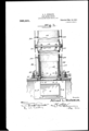
- draw- -.-ii1 gs:%- Figure 1 is view in elevationfpartly in vertical section and broken away showing fthe apparatus constructed. in accordance -with this invention, applied to aslibmarine partlyjin longitudinal section and hl oken ,away, of a. portion of the apparatus employed in accordance with this invention.
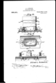
- w ig., 3 is a plan view, partly in horizontal section of the base portion of the device shown in Fig. 2.
- Fig; 4: is a detail view in i'or'igiiniolinal se'ction'of a portion of the apparatus employed in accordance with this l invention. 40.7
- FIG. 2 is a detail view ineletgition
- the hatch cover 3 is fastened I over the opening 2in any suitable manner as is here shown preferably by means'of v screw bolts 5 which-project through holes 6 in the hatch 3 and are held in threz ni ed en? gageinent with socket in the wall of the hull of the boat
- the hatch 3 overlaps the sides of the opening 2" and has on its up er surface and Secured thereto in any suita 1e manner a water proof 'sheet 3 which bears against the under side of theinner wall of the hull of the submarine boat to form a water tightjoint.
- the packing 4 isreferably composed 'of a 'thin'sheet of WO .v 4' se-' cured to the top of the water proof sheet 3', a sheet of-water' proof mater al 5 secured to the top ofthe wooden sheet 4 and a thick wooden plate 6 securedto the top of the .sheet 5, the 'whole forming a packing'whic'h fills the opening] 2 and fornis a water tight joint by reason of the edges of the' water proof sheet 5 bearin ngainst the side'of the opening 2, all as shown in- Fig. 4; This construction, as showngin' Fig.
- the main pipe should be formed of several sections by means of nuts and bolts 21.
- a pipe so formed in sections may be of any length dej sired in order to reach from the surface of the pi the water to a sunken submarine vessel resting onthe bottom ofthe ocean.
- the pipe may be len thened or shortened by assem- ⁇ bling a pre erred number of sections secured together 'as hereinbefore explained.
- This structure herein before described is lowered from the deck of a battle ship or cruiser. to. the sunken submarine boat and secured thereto.
- a hatch or plate 22 with a water proof packing 22 on the top thereof is placed over the opening 9 in the plate 8, said packing and plate or hatch'22 fitting into a shoulder 23 in the plate 8 and is secured in place in any safe manner, as for instance, by means of screws .25 extending through the plate 22, packing 22and into the plate 8.
- the plate 8 is se-' cured to the hull of the submarine in any. suitable manner and as here shown prefer ably bymeans of anumber of threaded bolts 26 which when the pipe is not secured to the hull of a submarine are coveredby means of ca 27 secured-to the-same.
- a water proof cement 30 or other suitable material is placed over thefiange l1 and covers the screws 12.
- a waterproof packing 31 is interposed bet-ween the late 8 and the hull of.
- the pipe can be of any suitable size and if desired of suflieient diameter to enable men to be drawn up through the same to the deck of the battle ship.
- the top' of the pipe is provided with a detachable cover 35 which may be employed in putting the pipe into place so that in case it slips water can not entensame. Of course, whencommunication has been made with-the inside of the submarine the cover" 35 is removed.
- a water tight closure is provided for submarine boats which may be readily unfastened, and also, 'a water proof pipe is provided which is adapted to be securely fastened to the submarine and permitof communication being made with.
Landscapes
- Engineering & Computer Science (AREA)
- Mechanical Engineering (AREA)
- Aviation & Aerospace Engineering (AREA)
- Gasket Seals (AREA)
Description
- A. L. BIDEAUX.
LIFE SAVING DEVICE. Al rLmu'xon FILED JULY 2s, 1910.
9863,4931. I Patented Mar.14,1911
2 SHEETSSHEET 1.
- imme/Mop Alfred .L..E|i.d aaux,
A. L. BIDEAUX.
LIFE SAVING DEVICE. APPLIOATIOR FILED JULY 2a, 1910.
986,431. Patented Man-14,1911.
' 2 sHEBTS-QHBE'I 2.
ninnn L. mnnsnx, or nnoo'knrn, new ronx.
mrnnr orricn.
Lirnsnvme nnvxcn.
jf Z'o all whom it my consent:
Be it known that I, ALFRED L. Bnimux, a
-,cjitiz enof the United States, residin at Brooklyn, in the county ofKing's and tate of New York, have invented certain new and jijlseflil Improvements in Life- Saving Deyices, of which the following is a specifica- ,;'tion, reference. being had therein to the ac- Loom anying'drawing. v v "1 is ll'lVGntlOIl relates to an apparatus for "'elainied'.- 1
25 Referring to the accompanying; draw- -.-ii1 gs:%-Figure 1 ;is view in elevationfpartly in vertical section and broken away showing fthe apparatus constructed. in accordance -with this invention, applied to aslibmarine partlyjin longitudinal section and hl oken ,away, of a. portion of the apparatus employed in accordance with this invention. w ig., 3 is a plan view, partly in horizontal section of the base portion of the device shown in Fig. 2. Fig; 4: is a detail view in i'or'igiiniolinal se'ction'of a portion of the apparatus employed in accordance with this l invention. 40.7
q-ided with a man hole 2 which is adapted; to be closed by a suitable cover or hatch 3. It
is preferably hinged on' the' side of the-hull efi of the submarine; boat at oneside ofi'the l gopening 2 and is adapted to be swung up and close said openin the opening 2 the hatch 'or cover 3 is provided with a packing 4v which fits into the Specification of Letters 1 mm.
Application filed July as, 1910. Serial no. 578,497.
a-vessel. Fig. 2 is a detail view ineletgition,
Referring to the drawings l' i ndicates -a {portion of the hull of a submarine boat pro In order tomake a water tight joint' with Pate ted Mar. 14, 1911.
opening 2. The hatch cover 3 is fastened I over the opening 2in any suitable manner as is here shown preferably by means'of v screw bolts 5 which-project through holes 6 in the hatch 3 and are held in threz ni ed en? gageinent with socket in the wall of the hull of the boat The hatch 3 overlaps the sides of the opening 2" and has on its up er surface and Secured thereto in any suita 1e manner a water proof 'sheet 3 which bears against the under side of theinner wall of the hull of the submarine boat to form a water tightjoint. The packing 4 isreferably composed 'of a 'thin'sheet of WO .v 4' se-' cured to the top of the water proof sheet 3', a sheet of-water' proof mater al 5 secured to the top ofthe wooden sheet 4 and a thick wooden plate 6 securedto the top of the .sheet 5, the 'whole forming a packing'whic'h fills the opening] 2 and fornis a water tight joint by reason of the edges of the' water proof sheet 5 bearin ngainst the side'of the opening 2, all as shown in- Fig. 4; This construction, as showngin' Fig. 4, remains in such position while the-submarine boat is in In order to have access to the persons Within the submarine boat when it has an apparatus is provided constructed and arranged and secured to the submarine boat .80 as follows -8 Indicates a'met-allic plate preferably of oblong rectangular shapaas'shown in- Fig. 3, and provided with a central opening or man hole 9. Upon theplate 8--'-='is mounted a vertical tube pr'eferably, construc'te'd as follows: 10. indicates a vertical short section of the tubehaving'formed at its lower end a circumferential flang'e'll by means of which the tube "l0' -is secured to the plate 8 in any suitable manner, asfor 1nstance by meansof I screws.,;12.. Extendlng over the vertical-tube 10 is the -lower end 13 of a pipe which vis of considerable length and is preferabl formed in sections.v The ipe 13,and the tube 10 are securedtogether y rivets and are, also clamped together by means of ainetallic strap '14 extendm about the pipe 13 and having ears 15 which are clamped together by means of a .bolt 16 and nut '17. As heretofore stated the main pipe should be formed of several sections by means of nuts and bolts 21. A pipe so formed in sections may be of any length dej sired in order to reach from the surface of the pi the water to a sunken submarine vessel resting onthe bottom ofthe ocean. The pipe may be len thened or shortened by assem-\ bling a pre erred number of sections secured together 'as hereinbefore explained. This structure herein before described is lowered from the deck of a battle ship or cruiser. to. the sunken submarine boat and secured thereto.
In order that water may not ooze up into e when it is lowered, the lower end thereo is closed as follows. A hatch or plate 22 with a water proof packing 22 on the top thereof is placed over the opening 9 in the plate 8, said packing and plate or hatch'22 fitting into a shoulder 23 in the plate 8 and is secured in place in any safe manner, as for instance, by means of screws .25 extending through the plate 22, packing 22and into the plate 8. The plate 8 is se-' cured to the hull of the submarine in any. suitable manner and as here shown prefer ably bymeans of anumber of threaded bolts 26 which when the pipe is not secured to the hull of a submarine are coveredby means of ca 27 secured-to the-same.
Vhen it is desired to secure the pipe to a submarine, divers descend .from a cruiser, remove the caps 27, and the pipe being lo-' cated over the manhole 9, the bolts 26 projeet up through holes 26 in the plate 8 and the latter is secured firmly in place by means .of washers 28and nuts 29.
. In order to make a water proof joint on theglower end oi the'tube 10 a water proof cement 30 or other suitable material is placed over thefiange l1 and covers the screws 12.
In order. to form a water. tight jointv be-,
tween the platefi and the-hull of the submarine a waterproof packing 31 is interposed bet-ween the late 8 and the hull of.
the submarine and. eld tightly in place b means of'the nuts29 and the bolts 26. The pipe formed in sections as herein, before. described may be lowered and raised-by .any suitable means andas here shown, preferably by means of the rods 32 secured at their lower ends to the rings 33 fastened to .60
the plate Biandjextending up through rings 34 mountedon the sides of the 'sectiqns of imprisoned therein.
When it is desired to have access to and rescue the crew of a sunken submarine bout imprisoned therein, divers descend and at tach the pipe as herein before described to the submarine over theo ening 9. The divers then tap on the side of the submarine for a signal to the persons imprisoned there in and the latter then remove the bolts 5 and open the door or hatch 3, remove the screws 25 from the hatch or plate 22 and remove the latter from the opening 9. Access may then be had to the inside of the submarine and the people on the battle ship or cruiser can send food and other material to the men in the submarine and can carry on telephonic" connection therewith if desired. It will be seen that the pipeextending from the sub marine above the surface of the water brings air to the persons down in the submarine.
The pipe can be of any suitable size and if desired of suflieient diameter to enable men to be drawn up through the same to the deck of the battle ship. The top' of the pipe is provided with a detachable cover 35 which may be employed in putting the pipe into place so that in case it slips water can not entensame. Of course, whencommunication has been made with-the inside of the submarine the cover" 35 is removed.
It' will be seen thatby'means of this.ap-
pa'ratus a water tight closure is provided for submarine boats which may be readily unfastened, and also, 'a water proof pipe is provided which is adapted to be securely fastened to the submarine and permitof communication being made with. the persons Having described the invention I claim 1. In an apparatus of the character described, a submarine boat having a man hole,
a hatch detachably secured on the under sideof said man hole and having a water proof packing'fi'lling said manhole, a water, proof packing-with a central opening surrounding saidman hole and located on the outer side elf said. submarine boat, a late extending oversaid' waterproof packing and having a central man hole communicating withthe manholeof the-submarineb oat, a hatch with a. water 'prootpackin covering said man hole in: said plate and ,tachably secured on the under side thereof, means for detachably securing the plate located on the out sidev of said submarine boat and a verticalw stand pipe formed in detachableseetions, and secured,- to said plate and. communicating with said man hole.
' 2. In an apparatus of the character described, a stand pipe formed in sections, a
short tube having an external annular flange at its lower end, saidttube fitting Within the lower end of said stand pipe and having flange of said shorttube and detachabl'y sea detachable hatch extending over and seat- 10 its flange bearing against the lower end of said stand pipe, a plate having a man-hole ed in the man-hole of said plate. located at the lower end of said short tube, In testimony whereof I hereunto a fiix my said plate extending beyond the annular signature in presence of two Witnesses.
ALFRED L. BIDEAUX.
cured the Jeto, and provided with means for securing it'to the hull of a tqrpedo boat, VVitnesses': v hoisting means connected to said p1ate,-and BENJ. T. HOOK, attached to the sides pf said stand pipe, and i JOHN G, AUPERIN.
Priority Applications (1)
| Application Number | Priority Date | Filing Date | Title |
|---|---|---|---|
| US57349710A US986431A (en) | 1910-07-23 | 1910-07-23 | Life-saving device. |
Applications Claiming Priority (1)
| Application Number | Priority Date | Filing Date | Title |
|---|---|---|---|
| US57349710A US986431A (en) | 1910-07-23 | 1910-07-23 | Life-saving device. |
Publications (1)
| Publication Number | Publication Date |
|---|---|
| US986431A true US986431A (en) | 1911-03-14 |
Family
ID=3054772
Family Applications (1)
| Application Number | Title | Priority Date | Filing Date |
|---|---|---|---|
| US57349710A Expired - Lifetime US986431A (en) | 1910-07-23 | 1910-07-23 | Life-saving device. |
Country Status (1)
| Country | Link |
|---|---|
| US (1) | US986431A (en) |
Cited By (1)
| Publication number | Priority date | Publication date | Assignee | Title |
|---|---|---|---|---|
| US2998208A (en) * | 1958-07-01 | 1961-08-29 | Perna James Di | Double safety aeroplane |
-
1910
- 1910-07-23 US US57349710A patent/US986431A/en not_active Expired - Lifetime
Cited By (1)
| Publication number | Priority date | Publication date | Assignee | Title |
|---|---|---|---|---|
| US2998208A (en) * | 1958-07-01 | 1961-08-29 | Perna James Di | Double safety aeroplane |
Similar Documents
| Publication | Publication Date | Title |
|---|---|---|
| US986431A (en) | Life-saving device. | |
| RU183928U1 (en) | Submarine Pop-up Rescue Camera | |
| US1697020A (en) | Safety device for submarines | |
| US1847996A (en) | Submarine rescue emerging compartment | |
| US1838566A (en) | Submarine device | |
| US1916294A (en) | Rescue tower | |
| US1428012A (en) | Ufe-sa | |
| US1142768A (en) | Attachment for submarine boats. | |
| US1188888A (en) | Means to raise sunken vessels. | |
| US1259534A (en) | Submarine life-boat. | |
| US1156970A (en) | Safety apparatus for submarines. | |
| US1009123A (en) | Apparatus for raising sunken vessels. | |
| US1696053A (en) | Ship | |
| US1613594A (en) | Submarine safety apparatus | |
| US1283060A (en) | Leak-stopper. | |
| US1309736A (en) | Testing-tank for submarines | |
| US1188179A (en) | Detachable conning-tower and life-buoy. | |
| US1819918A (en) | Apparatus for rescuing crews of submarines | |
| US994611A (en) | Means for raising sunken vessels. | |
| US1899059A (en) | Submarine salvager | |
| US1019356A (en) | Submarine life-saving and observation tender. | |
| US1228756A (en) | Submarine supply-tender. | |
| SU59297A1 (en) | Submarine Rescue Apparatus | |
| US1816689A (en) | Attachment for submarines and ships | |
| US1790414A (en) | filbert |