US9863631B1 - Shoe light device and method - Google Patents
Shoe light device and method Download PDFInfo
- Publication number
- US9863631B1 US9863631B1 US14/214,961 US201414214961A US9863631B1 US 9863631 B1 US9863631 B1 US 9863631B1 US 201414214961 A US201414214961 A US 201414214961A US 9863631 B1 US9863631 B1 US 9863631B1
- Authority
- US
- United States
- Prior art keywords
- shoe
- light
- attachment element
- lock
- housing
- Prior art date
- Legal status (The legal status is an assumption and is not a legal conclusion. Google has not performed a legal analysis and makes no representation as to the accuracy of the status listed.)
- Active - Reinstated, expires
Links
Images


Classifications
-
- F—MECHANICAL ENGINEERING; LIGHTING; HEATING; WEAPONS; BLASTING
- F21—LIGHTING
- F21V—FUNCTIONAL FEATURES OR DETAILS OF LIGHTING DEVICES OR SYSTEMS THEREOF; STRUCTURAL COMBINATIONS OF LIGHTING DEVICES WITH OTHER ARTICLES, NOT OTHERWISE PROVIDED FOR
- F21V33/00—Structural combinations of lighting devices with other articles, not otherwise provided for
- F21V33/0064—Health, life-saving or fire-fighting equipment
- F21V33/0076—Safety or security signalisation, e.g. smoke or burglar alarms, earthquake detectors; Self-defence devices
-
- A43B3/001—
-
- A—HUMAN NECESSITIES
- A43—FOOTWEAR
- A43B—CHARACTERISTIC FEATURES OF FOOTWEAR; PARTS OF FOOTWEAR
- A43B3/00—Footwear characterised by the shape or the use
- A43B3/34—Footwear characterised by the shape or the use with electrical or electronic arrangements
- A43B3/36—Footwear characterised by the shape or the use with electrical or electronic arrangements with light sources
-
- F—MECHANICAL ENGINEERING; LIGHTING; HEATING; WEAPONS; BLASTING
- F21—LIGHTING
- F21L—LIGHTING DEVICES OR SYSTEMS THEREOF, BEING PORTABLE OR SPECIALLY ADAPTED FOR TRANSPORTATION
- F21L4/00—Electric lighting devices with self-contained electric batteries or cells
- F21L4/02—Electric lighting devices with self-contained electric batteries or cells characterised by the provision of two or more light sources
-
- F—MECHANICAL ENGINEERING; LIGHTING; HEATING; WEAPONS; BLASTING
- F21—LIGHTING
- F21L—LIGHTING DEVICES OR SYSTEMS THEREOF, BEING PORTABLE OR SPECIALLY ADAPTED FOR TRANSPORTATION
- F21L4/00—Electric lighting devices with self-contained electric batteries or cells
- F21L4/08—Electric lighting devices with self-contained electric batteries or cells characterised by means for in situ recharging of the batteries or cells
-
- F—MECHANICAL ENGINEERING; LIGHTING; HEATING; WEAPONS; BLASTING
- F21—LIGHTING
- F21S—NON-PORTABLE LIGHTING DEVICES; SYSTEMS THEREOF; VEHICLE LIGHTING DEVICES SPECIALLY ADAPTED FOR VEHICLE EXTERIORS
- F21S9/00—Lighting devices with a built-in power supply; Systems employing lighting devices with a built-in power supply
- F21S9/02—Lighting devices with a built-in power supply; Systems employing lighting devices with a built-in power supply the power supply being a battery or accumulator
-
- F—MECHANICAL ENGINEERING; LIGHTING; HEATING; WEAPONS; BLASTING
- F21—LIGHTING
- F21V—FUNCTIONAL FEATURES OR DETAILS OF LIGHTING DEVICES OR SYSTEMS THEREOF; STRUCTURAL COMBINATIONS OF LIGHTING DEVICES WITH OTHER ARTICLES, NOT OTHERWISE PROVIDED FOR
- F21V21/00—Supporting, suspending, or attaching arrangements for lighting devices; Hand grips
- F21V21/08—Devices for easy attachment to any desired place, e.g. clip, clamp, magnet
- F21V21/088—Clips; Clamps
- F21V21/0885—Clips; Clamps for portable lighting devices
-
- F—MECHANICAL ENGINEERING; LIGHTING; HEATING; WEAPONS; BLASTING
- F21—LIGHTING
- F21V—FUNCTIONAL FEATURES OR DETAILS OF LIGHTING DEVICES OR SYSTEMS THEREOF; STRUCTURAL COMBINATIONS OF LIGHTING DEVICES WITH OTHER ARTICLES, NOT OTHERWISE PROVIDED FOR
- F21V33/00—Structural combinations of lighting devices with other articles, not otherwise provided for
- F21V33/0004—Personal or domestic articles
- F21V33/0008—Clothing or clothing accessories, e.g. scarfs, gloves or belts
-
- F—MECHANICAL ENGINEERING; LIGHTING; HEATING; WEAPONS; BLASTING
- F21—LIGHTING
- F21W—INDEXING SCHEME ASSOCIATED WITH SUBCLASSES F21K, F21L, F21S and F21V, RELATING TO USES OR APPLICATIONS OF LIGHTING DEVICES OR SYSTEMS
- F21W2111/00—Use or application of lighting devices or systems for signalling, marking or indicating, not provided for in codes F21W2102/00 – F21W2107/00
- F21W2111/10—Use or application of lighting devices or systems for signalling, marking or indicating, not provided for in codes F21W2102/00 – F21W2107/00 for personal use, e.g. hand-held
-
- F—MECHANICAL ENGINEERING; LIGHTING; HEATING; WEAPONS; BLASTING
- F21—LIGHTING
- F21Y—INDEXING SCHEME ASSOCIATED WITH SUBCLASSES F21K, F21L, F21S and F21V, RELATING TO THE FORM OR THE KIND OF THE LIGHT SOURCES OR OF THE COLOUR OF THE LIGHT EMITTED
- F21Y2101/00—Point-like light sources
-
- F21Y2101/02—
-
- F—MECHANICAL ENGINEERING; LIGHTING; HEATING; WEAPONS; BLASTING
- F21—LIGHTING
- F21Y—INDEXING SCHEME ASSOCIATED WITH SUBCLASSES F21K, F21L, F21S and F21V, RELATING TO THE FORM OR THE KIND OF THE LIGHT SOURCES OR OF THE COLOUR OF THE LIGHT EMITTED
- F21Y2115/00—Light-generating elements of semiconductor light sources
- F21Y2115/10—Light-emitting diodes [LED]
Definitions
- the present invention generally relates to portable lighting devices, and more particularly, to portable lighting devices attachable to shoes or footgear for lighting the path of a runner or walker.
- Night time running safety products are generally divided into two categories, those that provide visibility of the runner or walker, such as reflective clothing, vests and blinking lights, and those that assist the runner in seeing like headlamps and hand-held lights.
- Night RunnerTM shoe lights safely lights the way for running and walking at night.
- a pair of LED light units are powered by a rechargeable battery designed to keep runners and walkers safe and injury free.
- the light units attach to the shoelaces to provide advance warning of trip hazards and increase the runners and walkers visibility to traffic.
- the units are small, light, and unobtrusive to the running and walking experience.
- the unique motion of the shoe lights during running or walking captures the attention of drivers.
- the shoe lights provide illumination of hazards and traffic.
- FIG. 1 is a perspective view of one embodiment of a shoe light.
- FIG. 2 is a top view of the shoe light of FIG. 1 shown attached to a shoe.
- FIG. 3 is a perspective view of the shoe light of FIG. 1 shown attached to a shoe.
- FIG. 4A is a side perspective view of a ball joint.
- FIGS. 4B and 4C are side perspective views of a light housing mounted on the ball joint of FIG. 4A .
- FIG. 5A is a side perspective view of a magnet joint.
- FIG. 5B is side perspective view of a light housing mounted on the magnet joint of FIG. 5A .
- FIG. 6A is a top perspective view of a hinge.
- FIG. 6B is side view of the hinge of FIG. 6A .
- FIG. 6C is a top perspective view of a hinge with a locking knob.
- FIG. 7A is a top perspective view of a spring hinge.
- FIG. 7B is a side view of the spring hinge of FIG. 7A .
- FIG. 8 is top perspective view of an interlocking hinge.
- FIG. 9A is a top perspective view of a pivot knob.
- FIG. 9B is a side view of the pivot knob of FIG. 9A .
- FIG. 10A is a side perspective view of a clip lock hinge.
- FIG. 10B is a detailed view of clip lock being inserted on the clip lock hinge of FIG. 10A .
- FIG. 11A is a side perspective view of a metal pivot track.
- FIG. 11B is a side perspective view of the metal pivot track of FIG. 11A .
- FIG. 12A is a side view of a spring clip slide lace attachment element.
- FIG. 12B is a top perspective view of the spring clip slide of FIG. 12A attached to shoe laces.
- FIG. 13A is a side view of a torque with clip lace attachment element attached to shoe laces.
- FIG. 13B is a side view of the torque with clip of FIG. 13A .
- FIG. 14A is a side view of a hinge and snap lace attachment element attached to shoe laces.
- FIG. 14B is a side perspective view of the hinge and snap of FIG. 14A in an open orientation.
- FIG. 15A is a top perspective view of a soft hook and loop strap lace attachment element attached to shoe laces.
- FIG. 15B is a side perspective view of the soft hook and loop strap of FIG. 15A in an open orientation.
- FIG. 16 is a top perspective view of a fixed mounting plate lace attachment element attached to shoe laces.
- FIG. 17 is a top perspective view of a rubber friction plate lace attachment element attached to shoe laces.
- FIG. 18 is an exploded top perspective view of a magnet lock lace attachment element positioned relative to shoe laces.
- FIG. 19A is a top perspective view of a twist lock screw lace attachment element which may be positioned relative to shoe laces.
- FIG. 19B is an exploded top perspective view of the twist lock screw of FIG. 19A .
- FIG. 20A is a top perspective view of a spring lock lace attachment element in an open orientation.
- FIG. 20B is a top perspective view of the spring lock of FIG. 20A in a closed orientation.
- FIG. 21 is a top perspective view of a criss cross lace attachment element.
- FIG. 22A is a top exploded perspective view of a slide lock lace attachment element.
- FIG. 22B is a side exploded view of the slide lock of FIG. 22A .
- FIG. 23 is a top exploded perspective view of a top slide lock.
- FIG. 24A is a top exploded perspective view of a hairclip lace attachment element.
- FIG. 24B is a side view of the hairclip lace attachment element of FIG. 24A in an open orientation.
- FIG. 24C is a side view of the hairclip lace attachment element of FIG. 24A in a closed orientation.
- FIG. 25 is a top perspective view of a flex lock lace attachment element.
- FIG. 26A is a top exploded perspective view of a cross lock lace attachment element.
- FIG. 26B is a side view of the cross lock lace attachment element of FIG. 26A in a closed orientation.
- FIG. 27 is a top exploded perspective view of a snap lock lace attachment element.
- FIG. 28 is a top perspective view of a living hinge lock lace attachment element.
- FIG. 29A is a side view of a press lock lace attachment element in an unlocked orientation.
- FIG. 29B is a side view of a press lock lace attachment element of FIG. 29A in a locked orientation.
- FIG. 30A is a top perspective view of a cam lock lace attachment element.
- FIG. 30B is a top perspective view of the cam lock lace attachment element of FIG. 30A in a locked orientation.
- FIG. 31 is a top perspective view of a twist lock lace attachment element.
- FIG. 32 is a top perspective view of a track lock lace attachment element.
- FIG. 33A-33E are top perspective views of various light housings.
- FIGS. 34A, 34B, 35A, 35B, 36A, 36B, 37A, and 37B are top and side views of various light housings.
- FIGS. 38A-38F are top, side, front, and rear views of a light housing.
- FIGS. 39A-39E are top and side views of a light housing.
- FIG. 40 is top perspective view of a light housing mounted on a shoe.
- FIG. 41 is top perspective view of a light housing mounted on a shoe.
- FIG. 42 is a side perspective view of a light housing mounted on an in-line skate.
- FIG. 43A is an end perspective view of a light housing mounted on a shoe with a band.
- FIG. 43B is an end perspective close-up view of the light housing of FIG. 43A .
- FIG. 43C is a side view of the light housing of FIG. 43A .
- FIG. 43D is a side perspective view of the light housing of FIG. 43 showing the band inserted under the shoe laces.
- FIG. 44A is an end perspective view of a light housing mounted on a lace attachment element.
- FIG. 44B is an end perspective close-up view of the light housing of FIG. 44A .
- FIG. 44C is a top view of the light housing of FIG. 44A .
- FIG. 45A is an end perspective view of a light housing mounted on a lace attachment element.
- FIG. 45B is an end perspective close-up view of the light housing of FIG. 45A .
- FIG. 45C is an end perspective view of the light housing of FIG. 45A in a folded-down orientation.
- FIG. 45D is an end perspective view of the light housing of FIG. 45A in a folded-up orientation.
- FIG. 46 is an exploded view of a light housing that is contained by a lace attachment element.
- FIG. 47 is a top view of a pair of light housing modules projecting light at different angles.
- FIG. 48A is a top perspective view of the light housing modules of FIG. 47 mounted on a pair of shoes.
- FIG. 48B is a top view of a light housing module of FIG. 47 mounted on a of shoe.
- FIGS. 48C , D, E are top, side, and top perspective views of a light housing module of FIG. 47 .
- Night RunnerTM Shoe Lights comprise self-contained light housing modules which include an array of LEDs for front illumination, a rechargeable power system, and a single control button.
- the term “light source” means one or more LED, bulb, laser, Organic Light Emitting Diode (OLED), or other photon-generating element.
- LED shoe lights fasten securely to one or both shoes with shoe lace attachment elements, and have multi-position adjustability through a pivotal connection between the lace attachment element and the light housing.
- the light housing provides an encasement in a high impact plastic that is water resistant or waterproof.
- the light housing is designed to be easily removable from the lace attachment element.
- the lace attachment element has a first part that can stay attached to a shoe while a second part is detachable with the light housing.
- the light housing and the lace attachment element are easily removable from the shoe. The light housing can then be used with other support brackets for other sports and activities such as cycling, skiing, skateboarding, etc.
- the LED lights generate over fifty lumens (50+) in the smallest and lightest practical configuration.
- the water resistant or waterproof switch has 5 modes: high, low, interval, blinking and off.
- an indicator light is provided to alert when the battery needs to be recharged.
- side and rear facing marker lights allow the runner and walker to be seen from the side and rear.
- batteries are rechargeable and provide at least 10 hours of run time per charge.
- Battery recharging may be provided with a power transformer that plugs into an electrical outlet and provides power to a rechargeable battery through a USB port or other electrical connector.
- the term “power source” means one or more battery, or other supply of electrical current.
- power may be provided to the shoe lights through kinetic, motion charging, solar energy, electromagnetic harvesting or artificial photosynthesis.
- the term “rechargeable power source” means a rechargeable battery, or direct supply of electrical current, such as provided by the kinetic energy of the runner or walker.
- FIGS. 1-3 show an example shoe light 10 configured to be attachable to a shoe 11 of a walker or runner.
- the shoe light 10 may be configured to be releasably attached to a shoe 11 and may be adjusted relative to the shoe 11 such that as a user's foot strikes the ground, light is cast out in front of the shoe to illuminate the user's path.
- a user may attach a shoe light 10 to each shoe 11 , thereby enabling the user's path to be lit at all times.
- the shoe light comprises a lace attachment element, a light housing, and a pivotal connector between the lace attachment element and the light housing.
- the shoe light 10 is formed from a light housing 12 forming an outer shell 14 with an internal cavity 16 housing at least one light source 18 extending through at least one orifice 20 in the light housing 12 .
- the light source 18 is positioned to cast light in a first direction 22 from a first end 24 of the light housing 12 .
- the first direction is toward the front of the shoe.
- the light source 18 is formed from one or more LEDs. The LEDs may be aligned with each other or may be offset to broaden the width thorough which light is cast.
- the light housing 12 may include one or more power sources 54 within the internal cavity 16 .
- the power source 54 may be rechargeable.
- the power source 54 may be a battery or other appropriate energy source.
- the light housing 12 may also include an on/off switch 56 exposed through an orifice 58 in the light housing 12 , and in communication with the power source 54 and the light source 18 .
- the switch may provide a plurality of lighting modes—such as bright, dim, blinking, interval or other patterns.
- the lace attachment element is a releasable connector 26 formed from first and second arms 28 , 30 coupled together at a first end 32 and separated by a gap 34 forming an opening 36 between the first and second arms 28 , 30 at a second end 38 .
- the second end 38 of the releasable connector 26 is attached to a second end 40 of the light housing 12 .
- One or more retention teeth 60 may be positioned at the opening 36 to retain lace segments between the first and second arms 28 , 30 .
- the first and second arms 28 , 30 may be biased towards each other.
- the first arm 28 of the releasable connector 26 may have a convex surface 42 facing the second arm 30 such that the convex surface 42 is positioned in closer proximity to the second are 30 than the first arm 28 relative to the second are 30 at the first end 32 .
- the convex surface 42 may bind against the shoe laces.
- the first arm 38 of the releasable connector 26 may include an access orifice 44 positioned between first and second yoke arms 46 , 48 .
- the shoe light 10 may be attached to a shoe by inserting laces into the opening 36 between the first and second arms 28 , 30 .
- the shoe laces will generally extend orthogonally relative to the first and second arms 28 , 30 .
- the opening 36 may be configured such that the opening faces the toe of a shoe 11 when attached to a shoe 11 .
- the light housing 12 and releasable connector 26 hang on the laces from the first end 32 of the releasable connector 26 .
- the first end 32 of the releasable connector 26 where the first and second arms 28 , 30 are coupled together, bares against the laces with each foot strike.
- the releasable connector 26 in constantly pushed into the correct position with each and every foot strike.
- the shoe light 10 remains attached to a user's shoe 11 throughout a run.
- the releasable connector 26 is rotatably coupled to the light housing 12 with pivotal connector 52 .
- the second end 38 of the releasable connector 26 on the first and second yoke arms 46 , 48 of the first arm 28 each includes a pin housing 50 configured to receive a connector 52 .
- the connector 52 may be any appropriate member, such as, but not limited to, a threaded screw, a pin and a post.
- the releasable connector 26 and the light housing 12 may be formed from any appropriate material, such as, but not limited to, metal, such as aluminum, carbon fiber, plastic and combinations thereof.
- the shoe light 10 may be adjusted relative to the shoe 11 so that light is cast in the desired direction. More particularly, the light housing 12 may be rotated in an upward direction relative to the releasable connector 26 about the connector 52 . The connector 52 is tightened sufficiently such that the light housing 12 may stay in positioned relative to the releasable connector 26 while running or walking, yet enable a user to adjust the angle of the light housing 12 relative to the releasable connector 26 by hand without tools.
- the terms “pivotal attachment”, “pivotal connection”, and “pivotal connector” mean a joint or other attachment mechanism between a lace attachment element and a light housing, or between a lace attachment element and a light housing support platform.
- FIGS. 4-11 show several types of pivotal attachments that may be used with a shoe light.
- FIG. 4A is a side perspective view of a ball joint 210 comprising a socket 211 and a ball 212 .
- FIGS. 4B and 4C are side perspective views of a light housing 100 mounted on the ball joint 210 of FIG. 4A .
- the light housing is mounted on the socket portion of the ball joint. In other examples, the light housing is mounted on the ball portion of the ball joint.
- FIG. 5A is a side perspective view of a magnet joint 220 comprising a magnet 224 recessed in a socket 222 , and a steel ball 221 .
- FIG. 5B is side perspective view of a light housing 100 mounted on the magnet joint 220 of FIG. 5A .
- the socket is lined with rubber to provide a high friction against the steel ball.
- FIG. 6A is a top perspective view of a hinge 230 between a top element 231 and a bottom element 232 .
- the hinge includes a pin 235 and a pin housing 234 .
- FIG. 6B is side view of the hinge of FIG. 6A .
- FIG. 6C is a top perspective view of a hinge with a locking knob 236 that holds the top element 231 in a desired orientation with respect to the bottom element.
- FIG. 7A is a top perspective view of a spring hinge 240 between a top element 241 and a bottom element 242 .
- the spring hinge includes a spring 243 to force the top element toward the bottom element.
- FIG. 7B is side view of the spring hinge of FIG. 7A where the top element supports a light housing 100 , and an adjustment element 244 is used to set the desired orientation of the top element and light housing with respect to the bottom element.
- the bottom element is part of a lace attachment element.
- FIG. 8 is top perspective view of an interlocking hinge 250 between a top element 251 and a bottom element 252 .
- the hinge includes a pin 255 that is segmented so that portions of the pin are attached to both the top and bottom elements.
- the top element includes pin engagement elements 254
- the bottom element includes pin engagement elements 253 , so that the top and bottom elements can snap together along the segmented pin.
- FIG. 9A is a top perspective view of a pivot knob 260 between a light housing 100 and a bottom element 262 which is part of a lace attachment element.
- FIG. 9B is a side view of the pivot knob of FIG. 9A showing a locking screw 264 and nut 265 to hold the light housing in a desired orientation.
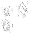
- FIG. 10A is a side perspective view of a clip lock hinge 270 between a top element 271 and a bottom element 272 .
- the top and bottom elements include extensions 274 and 275 which are held together with a slide-on clip lock 273 .
- FIG. 10B is a detailed view of clip lock 273 being inserted on the clip lock hinge of FIG. 10A .
- FIG. 11A is a side perspective view of a metal pivot track 280 with a top top element 281 and a bottom element 282 attached to a lace attachment element 283 .
- FIG. 11B is a side perspective view of the metal pivot track of FIG. 11A showing teeth 287 and 288 on the pivot surfaces of the top top element 281 and a bottom element 282 , a lock bolt 284 , nut 286 , and washers 285 and 289 .
- lace attachment element means a single element or combination of elements configured to be held in place on a shoe with respect to laces, strap(s), cord, hooks, or other closures on the shoe.
- FIGS. 12-32 show several types of lace attachment elements that may be used with a shoe light.
- FIG. 12A is a side view of a spring clip slide 310 lace attachment element showing a clip slide 312 which slides into housing 311 .
- FIG. 12B is a top perspective view of the spring clip slide of FIG. 12A attached to shoe lace segments 80 and 81 so that the laces are held between the clip slide and the housing.
- a light housing may be pivotally attached to the clip, such as with pivot holder 315 .
- FIG. 13A is a side view of a torque with clip 320 lace attachment element attached to shoe lace segments 80 and 81 .
- the clip includes a top portion 321 and a bottom portion 322 .
- FIG. 13B is a side view of the torque with clip of FIG. 13A .
- the light housing may be attached to or integral to the top element.
- FIG. 14A is a side view of a hinge and snap 330 lace attachment element attached to shoe lace segments 80 , 81 , 82 , and 83 .
- the hinge and snap includes a snap feature 334 on lower portion 332 which is inserted into a slot 335 on upper portion 331 to lock the device over the shoe lace segments.
- FIG. 14B is a side perspective view of the hinge and snap of FIG. 14A in an open orientation.
- FIG. 15A is a top perspective view of a soft hook and loop strap 340 lace attachment element attached to shoe laces.
- a hook and loop fastener is used to secure a top portion 341 to a bottom portion 342 , and to secure the device on shoe lace segments 80 and 81 .
- Either or both of the top and bottom portions may be soft, such as a heavy fabric.
- FIG. 15B is a side perspective view of the soft hook and loop strap of FIG. 15A in an open orientation.
- a light housing may be pivotally attached to the soft hook and loop strap, such as with pivot holder 345 .
- FIG. 16 is a top perspective view of a fixed mounting plate 350 lace attachment element attached to shoe laces by threading the lace segments through holes 351 , 352 , 353 , and 354 .
- a light housing may be pivotally attached to the plate, such as with pivot holder 355 .
- the plate may be rigid or soft, such as a fabric, leather, or soft polymer.
- FIG. 19A is a top perspective view of a twist lock screw 380 lace attachment element which may be positioned relative to shoe laces.
- FIG. 19B is an exploded top perspective view of the twist lock screw lace attachment element of FIG. 19A showing a screw 383 to attach the top portion 381 to the bottom portion 382 .
- FIG. 20A is a top perspective view of a spring lock 390 lace attachment element in an open orientation with arms 391 and 392 spaced apart and locking members 393 and 394 space apart. The device may be placed over shoe lace segments and then closed.
- FIG. 20B is a top perspective view of the spring lock of FIG. 20A in a closed orientation so that locking members 393 and 394 are engaged and holding arms 391 and 392 closer together.
- FIG. 21 is a top perspective view of a criss cross 400 lace attachment element.
- Soft or rigid plate includes slots 402 and 403 . Lace segments are directed through the slots to hold the plate in place on the shoe.
- a light housing may be pivotally attached to the plate, such as with pivot holder 405 .
- FIG. 22A is a top exploded perspective view of a slide lock 420 lace attachment element where bottom portion 422 slides into top portion 421 to hold lace segments between the bottom portion and the top portion.
- FIG. 22B is a side exploded view of the slide lock of FIG. 22A showing a slide receptacle 424 on the upper portion.
- FIG. 23 is a top exploded perspective view of a top slide lock 430 lace attachment element where a top portion 431 slides into bottom portion 432 to hold lace segments 80 and 81 between the bottom portion and the top portion.
- a light housing may be pivotally attached to the plate, such as with pivot holder 435 .
- the bottom portion may have integral rails 434 to accept the top portion, or rails may be provided on a compliant lower panel.
- FIG. 24A is a top exploded perspective view of a hairclip 440 lace attachment element with a top portion 441 and a bottom portion 442 .
- FIG. 24B is a side view of the hairclip lace attachment element of FIG. 24A in an open orientation with a space between top portion 441 and bottom portion 442 .
- FIG. 24C is a side view of the hairclip lace attachment element of FIG. 24A in a closed orientation where the top portion is compressed against bottom portion to hold the device in place over lace segments (not shown).
- FIG. 25 is a top perspective view of a flex lock 450 lace attachment element with a base plate 452 , a slot 453 , and a retention element 454 .
- the base plate is inserted below lace segments which are retained in slot 453 with retention element 454 .
- FIG. 26A is a top exploded perspective view of a cross lock 460 lace attachment element with a top portion 461 and a bottom portion 462 with lace inset features 463 and 464 to contain lace segments 80 and 81 .
- the top portion includes wrap-around end sections 465 and 466 that slide on or snap to the bottom portion to hold the top in place.
- FIG. 26B is a side view of the cross lock lace attachment element of FIG. 26A in a closed orientation with the wrap-around end sections 465 and 466 engaging the bottom portion 462 .
- FIG. 27 is a top exploded perspective view of a snap lock 470 lace attachment element with a top portion 471 and bottom portion 472 .
- the bottom portion includes projections 473 and 474 which snap into holes 475 and 476 on the top portion.
- two or more projections may be provided in the top portion.
- FIG. 28 is a top perspective view of a living hinge lock 480 lace attachment element with a living hinge 483 between a top portion 481 and a bottom portion 482 .
- the bottom portion includes a snap projection 484 to mate with a hole 486 in the top portion.
- FIG. 29A is a side view of a press lock 490 lace attachment element in an unlocked orientation.
- a plurality of projections 493 on the top portion 491 nest with a plurality of projections 494 on the bottom portion 492 to secure the top portion to the bottom portion as shown in FIG. 29B , which shows the device in a locked orientation.
- FIG. 30A is a top perspective view of a cam lock 500 lace attachment element where top portion 501 is secured to bottom portion 502 with a cam 503 which engages a slot 504 on the top portion.
- FIG. 30B is a top perspective view of the cam lock lace attachment element of FIG. 30A held in a locked orientation with cam 503 .
- FIG. 31 is a top perspective view of a twist lock 510 lace attachment element where the top portion 511 is secured to the bottom portion 512 with a twist lock 513 , and lace segments 80 and 81 are held between the top portion and the bottom portion.
- FIG. 32 is a top perspective view of a track lock 520 lace attachment element where the top portion 521 is secured to the bottom portion 522 with a lock 523 movable along a slot 524 , and lace segments 80 and 81 are held between the top portion and the bottom portion.
- FIG. 33A-33E are top perspective views of various light housings 601 , 602 , 603 , 604 , and 605 . These examples have various shapes and three to five LEDs.
- FIGS. 34-37 are top and side views of various light housings 610 , 620 , 630 , and 640 . These examples include forward-facing LEDs 611 , with and without forward lens covers 622 (not labeled), 632 , 642 ; rear-facing LEDs 613 , with and without lens covers 623 , 633 , and 643 . The examples shown each have single on/off and control button 615 , 625 , 635 , and 645 .
- FIGS. 38A-38F are top and side views of a light housing 650 with control button 655 .
- there are six forward-facing LEDs where LEDs 651 a and 651 b are directed at a first forward angle; LEDs 651 c and 651 d face forward; and LEDs 651 e and 651 f are directed at a second forward angle.
- There are four rear-facing LEDs where LEDs 652 a and 652 b are directed at a first rear-facing angle; and LEDs 652 c and 652 d are directed at a second rear-facing angle.
- a magnet 656 is provided on the light housing in order to removably attach the light housing to a lace attachment element.
- the example has a single on/off and control button 655 .
- FIGS. 39A-39E are top and side views of a light housing 660 with two rear-facing recessed LEDs and rear lens covers 662 a and 662 b .
- there are three forward-facing lens covers with cover 661 a directed at a first forward angle; cover 661 b facing forward; and cover 661 c directed at a second forward angle.
- the example has a single on/off and control button 665 .
- FIG. 40 is top perspective view of a light housing 670 mounted on a shoe 11 with lace attachment element 678 .
- the light housing has four recessed forward-facing LEDs 671 a , 671 b , 671 c , and 671 d .
- the housing includes a lip overhang 679 which serves to shield the LEDs from a runner's eyes.
- the example has a single on/off and control button 675 .
- FIG. 41 is top perspective view of a light housing 680 mounted on a shoe 11 with lace attachment element 678 .
- the light housing has three recessed forward-facing LEDs 681 a , 681 b , and 681 c .
- the housing includes a lip overhang 689 which serves to shield the LEDs from a runner's eyes.
- the example has a single on/off and control button 685 .
- FIG. 42 is side perspective view of a light housing 690 mounted on an in-line skate 90 .
- FIG. 43A is an end perspective view of a light housing 700 mounted on a shoe 11 with a band 720 .
- the light housing is a thin panel 710 with a plurality of LEDs 701 which may be mounted on a flexible circuit board.
- FIG. 43B is an end perspective close-up view of the light housing 700 of FIG. 43A .
- FIG. 43C is a side view of the light housing 700 of FIG. 43 .
- FIG. 43D is a side perspective view of the light housing of FIG. 43 showing the band inserted under the shoe laces.
- the light housing is designed to be inserted into a slot 722 on the band, so that the light panel is maintained at a desired angle with respect to the shoe.
- a hook and loop fastener, or other closure element can be used to secure the light housing to the band.
- FIG. 44A is an end perspective view of a light housing 740 mounted on a lace attachment element 748 .
- FIG. 44B is an end perspective close-up view of the light housing 740 of FIG. 44A .
- FIG. 43C is a top view of the light housing 740 of FIG. 44A .
- FIG. 45A is an end perspective view of a light housing 770 mounted on a lace attachment element 778 .
- FIG. 45B is an end perspective close-up view of the light housing 770 of FIG. 45A .
- FIG. 45C is an end perspective view of the light housing 770 of FIG. 45A in a folded-down orientation.
- FIG. 45D is an end perspective view of the light housing 770 of FIG. 45A in a folded-up orientation.
- FIG. 46 is an exploded view of a light housing 800 that is contained by a lace attachment element 820 .
- a portion of the light housing may be pivotal and adjustable, or the light housing may be fixed so that the light is projected at an upward angle 840 with respect to the longitudinal axis 830 of the light module.
- FIG. 47 is a top view of a pair of light housing modules 900 and 950 projecting light at different angles. Just as the feet have a bilateral symmetry, in this example, there are left and right LED light units that are a mirror image of the other.
- each unit 900 and 950 would be pushed forward and contain a larger LED light with a beam that overlaps the opposite units beam.
- the edge of each light unit would recede back in an arc to mimic the relative proportions of the forward big toe to the smaller end toe. Smaller lights would be along the curve and their overlapping beams would project forward and to the side of the runner or walker.
- the rear facing red side markers would be on the outside of the units with their light beams projecting out at a backward and side angle for rear and side visibility.
- the two units would nest together when off the shoes to form an arc and a bilateral symmetrical design. This “Left-Right Technology” compliments the modern design of running shoes which have a bilateral symmetry.
- FIG. 48A is a top perspective view of the light housing modules of FIG. 47 mounted on a pair of shoes 80 and 81 .
- FIG. 48B is a top view of a light housing module 900 of FIG. 47 mounted on a of shoe 80 .
- FIGS. 48C , D, E are top, side, and top perspective views of a light housing module 900 of FIG. 47 .
- the light units will be powered by a rechargeable battery system such as a Li-ion rechargeable battery with USB port and wall charger adapter.
- a “Y” connector can accommodate charging both units at the same time from a standard wall-charging plug in module.
- a charging base will hold both units for ease of charging and non-use storage.
- Kinetic Motion Recharging technology is used to recharge the power supply.
- motion charging, solar energy, electromagnetic harvesting, or artificial photosynthesis are used to recharge the power supply.
- Bluetooth GPS enabled flash interval timers alert runners and walkers to pre determined time or distance milestones.
- remote switching allows runners and walkers to remotely operate light units.
- smart phone integration would provide compatibility with various sport and fitness smart phone applications.
- battery conservation features would be provided, such as the lights switching off when in the up back-kick position.
- the light housing may include, a translucent glowing case to enhance design, visibility and desirability.
- Flash Interval timers can mark increments of time (such as every 5 minutes, 1 minute, repeat)
- a battery level identification can be provided, such as through side red LEDs.
- Specialty brackets can be provided fro other sports or activities so that the light housing can be removed from a shoe and used in the bracket.
- the shoe lights are provided as a kit comprising two shoe lights and a recharging unit.
Landscapes
- Engineering & Computer Science (AREA)
- General Engineering & Computer Science (AREA)
- Computer Security & Cryptography (AREA)
- Environmental & Geological Engineering (AREA)
- Microelectronics & Electronic Packaging (AREA)
- Footwear And Its Accessory, Manufacturing Method And Apparatuses (AREA)
Abstract
Description
Claims (15)
Priority Applications (1)
| Application Number | Priority Date | Filing Date | Title |
|---|---|---|---|
| US14/214,961 US9863631B1 (en) | 2013-03-15 | 2014-03-16 | Shoe light device and method |
Applications Claiming Priority (2)
| Application Number | Priority Date | Filing Date | Title |
|---|---|---|---|
| US201361793594P | 2013-03-15 | 2013-03-15 | |
| US14/214,961 US9863631B1 (en) | 2013-03-15 | 2014-03-16 | Shoe light device and method |
Publications (1)
| Publication Number | Publication Date |
|---|---|
| US9863631B1 true US9863631B1 (en) | 2018-01-09 |
Family
ID=60813509
Family Applications (1)
| Application Number | Title | Priority Date | Filing Date |
|---|---|---|---|
| US14/214,961 Active - Reinstated 2035-03-10 US9863631B1 (en) | 2013-03-15 | 2014-03-16 | Shoe light device and method |
Country Status (1)
| Country | Link |
|---|---|
| US (1) | US9863631B1 (en) |
Cited By (3)
| Publication number | Priority date | Publication date | Assignee | Title |
|---|---|---|---|---|
| USD962822S1 (en) * | 2020-11-18 | 2022-09-06 | Timothy Callahan | Hat clip flag holder |
| DE202023106192U1 (en) | 2023-10-26 | 2023-11-30 | Moritz Wolfram Schröder | Portable lighting device |
| US20250347394A1 (en) * | 2024-05-07 | 2025-11-13 | Gary Berreth | Hands Free Flashlight Device |
Citations (16)
| Publication number | Priority date | Publication date | Assignee | Title |
|---|---|---|---|---|
| US2671847A (en) * | 1951-09-25 | 1954-03-09 | Louis A Lerch | Toe light |
| US3067322A (en) * | 1960-12-29 | 1962-12-04 | Errett O Sala | Light for foot apparel |
| US6122340A (en) * | 1998-10-01 | 2000-09-19 | Personal Electronic Devices, Inc. | Detachable foot mount for electronic device |
| US20030021105A1 (en) * | 2001-07-26 | 2003-01-30 | The Coleman Company, Inc. | Light with clamp that fits into a headband |
| US20030026093A1 (en) * | 2001-08-03 | 2003-02-06 | Sandberg Robert J. | Device for holding a light source |
| US20050052883A1 (en) * | 2002-02-25 | 2005-03-10 | Chen Qi | Optical fiber decoration device using led light source and article decorated thereby |
| US7200517B2 (en) * | 1997-10-02 | 2007-04-03 | Nike, Inc. | Monitoring activity of a user in locomotion on foot |
| US20070109768A1 (en) * | 2003-01-22 | 2007-05-17 | Sohn Dae U | Clip type light detachably coupled with cap |
| US20070130804A1 (en) * | 2005-12-14 | 2007-06-14 | Bernard Levy | Step over walking aid |
| US20080253108A1 (en) * | 2007-04-05 | 2008-10-16 | Dpm Associates, Llc | Illuminating Footwear Accessory |
| US20090059607A1 (en) * | 2007-08-27 | 2009-03-05 | Aitec Co., Ltd. | Lamp Support |
| USD614345S1 (en) * | 2009-12-09 | 2010-04-20 | Life+Gear, Inc. | Light clip |
| US20130215607A1 (en) * | 2011-01-03 | 2013-08-22 | Nite Ize, Inc. | Personal lighting device |
| US8550652B2 (en) * | 2010-05-25 | 2013-10-08 | Shen-Ko Tseng | Light-emitting decoration |
| US20130301034A1 (en) * | 2012-01-12 | 2013-11-14 | Goodlux Technology, Llc | Light Therapy Monitoring |
| US20140009921A1 (en) * | 2012-07-09 | 2014-01-09 | Blackbeam Llc | Flashlight with integrated clip in handle |
-
2014
- 2014-03-16 US US14/214,961 patent/US9863631B1/en active Active - Reinstated
Patent Citations (16)
| Publication number | Priority date | Publication date | Assignee | Title |
|---|---|---|---|---|
| US2671847A (en) * | 1951-09-25 | 1954-03-09 | Louis A Lerch | Toe light |
| US3067322A (en) * | 1960-12-29 | 1962-12-04 | Errett O Sala | Light for foot apparel |
| US7200517B2 (en) * | 1997-10-02 | 2007-04-03 | Nike, Inc. | Monitoring activity of a user in locomotion on foot |
| US6122340A (en) * | 1998-10-01 | 2000-09-19 | Personal Electronic Devices, Inc. | Detachable foot mount for electronic device |
| US20030021105A1 (en) * | 2001-07-26 | 2003-01-30 | The Coleman Company, Inc. | Light with clamp that fits into a headband |
| US20030026093A1 (en) * | 2001-08-03 | 2003-02-06 | Sandberg Robert J. | Device for holding a light source |
| US20050052883A1 (en) * | 2002-02-25 | 2005-03-10 | Chen Qi | Optical fiber decoration device using led light source and article decorated thereby |
| US20070109768A1 (en) * | 2003-01-22 | 2007-05-17 | Sohn Dae U | Clip type light detachably coupled with cap |
| US20070130804A1 (en) * | 2005-12-14 | 2007-06-14 | Bernard Levy | Step over walking aid |
| US20080253108A1 (en) * | 2007-04-05 | 2008-10-16 | Dpm Associates, Llc | Illuminating Footwear Accessory |
| US20090059607A1 (en) * | 2007-08-27 | 2009-03-05 | Aitec Co., Ltd. | Lamp Support |
| USD614345S1 (en) * | 2009-12-09 | 2010-04-20 | Life+Gear, Inc. | Light clip |
| US8550652B2 (en) * | 2010-05-25 | 2013-10-08 | Shen-Ko Tseng | Light-emitting decoration |
| US20130215607A1 (en) * | 2011-01-03 | 2013-08-22 | Nite Ize, Inc. | Personal lighting device |
| US20130301034A1 (en) * | 2012-01-12 | 2013-11-14 | Goodlux Technology, Llc | Light Therapy Monitoring |
| US20140009921A1 (en) * | 2012-07-09 | 2014-01-09 | Blackbeam Llc | Flashlight with integrated clip in handle |
Cited By (4)
| Publication number | Priority date | Publication date | Assignee | Title |
|---|---|---|---|---|
| USD962822S1 (en) * | 2020-11-18 | 2022-09-06 | Timothy Callahan | Hat clip flag holder |
| DE202023106192U1 (en) | 2023-10-26 | 2023-11-30 | Moritz Wolfram Schröder | Portable lighting device |
| EP4549810A1 (en) | 2023-10-26 | 2025-05-07 | Moritz Wolfram Schröder | Portable lighting device |
| US20250347394A1 (en) * | 2024-05-07 | 2025-11-13 | Gary Berreth | Hands Free Flashlight Device |
Similar Documents
| Publication | Publication Date | Title |
|---|---|---|
| US5738432A (en) | Illumination device and a method | |
| US20040100792A1 (en) | Illumination device for mounting on lace or strap of footwear | |
| US8087421B2 (en) | Illuminated apparatus for assisting movement | |
| US9829182B1 (en) | Helmet or head mounted bicycle lights | |
| US7377665B2 (en) | Buckle-mounted light | |
| US8992039B2 (en) | Lighting apparatus with detachable clip mount | |
| US8733989B1 (en) | Helmet mounted bicycle lights | |
| US6896389B1 (en) | Headmounted light | |
| EP2479489B1 (en) | Portable light assembly | |
| US8746264B2 (en) | Illuminated apparatus for assisting movement | |
| US8070308B1 (en) | Helmet mounted bicycle lights | |
| AU2008207968B2 (en) | Headlamp with adjustable diffuser lens | |
| US8157401B2 (en) | LED rechargeable headlamp | |
| US4438482A (en) | Illuminating device | |
| US20110170280A1 (en) | Shroud plate with lighting system | |
| US11959603B2 (en) | Multi-element flexible strap light | |
| US20080298048A1 (en) | Headlamp with detachable led flashlight | |
| US9863631B1 (en) | Shoe light device and method | |
| US20110310592A1 (en) | Directional Hands-Free Wrist Illumination Device | |
| US20210215326A1 (en) | Head lamp | |
| US6540384B1 (en) | Snowboard light | |
| US10548298B2 (en) | Dog collar light | |
| GB2441407A (en) | Visor with light | |
| JP2003272402A (en) | Portable lighting device |
Legal Events
| Date | Code | Title | Description |
|---|---|---|---|
| STCF | Information on status: patent grant |
Free format text: PATENTED CASE |
|
| FEPP | Fee payment procedure |
Free format text: MAINTENANCE FEE REMINDER MAILED (ORIGINAL EVENT CODE: REM.); ENTITY STATUS OF PATENT OWNER: MICROENTITY |
|
| LAPS | Lapse for failure to pay maintenance fees |
Free format text: PATENT EXPIRED FOR FAILURE TO PAY MAINTENANCE FEES (ORIGINAL EVENT CODE: EXP.); ENTITY STATUS OF PATENT OWNER: MICROENTITY |
|
| STCH | Information on status: patent discontinuation |
Free format text: PATENT EXPIRED DUE TO NONPAYMENT OF MAINTENANCE FEES UNDER 37 CFR 1.362 |
|
| FP | Lapsed due to failure to pay maintenance fee |
Effective date: 20220109 |
|
| PRDP | Patent reinstated due to the acceptance of a late maintenance fee |
Effective date: 20220316 |
|
| FEPP | Fee payment procedure |
Free format text: PETITION RELATED TO MAINTENANCE FEES FILED (ORIGINAL EVENT CODE: PMFP); ENTITY STATUS OF PATENT OWNER: MICROENTITY Free format text: PETITION RELATED TO MAINTENANCE FEES GRANTED (ORIGINAL EVENT CODE: PMFG); ENTITY STATUS OF PATENT OWNER: MICROENTITY Free format text: SURCHARGE, PETITION TO ACCEPT PYMT AFTER EXP, UNINTENTIONAL (ORIGINAL EVENT CODE: M3558); ENTITY STATUS OF PATENT OWNER: MICROENTITY |
|
| MAFP | Maintenance fee payment |
Free format text: PAYMENT OF MAINTENANCE FEE, 4TH YEAR, MICRO ENTITY (ORIGINAL EVENT CODE: M3551); ENTITY STATUS OF PATENT OWNER: MICROENTITY Year of fee payment: 4 |
|
| STCF | Information on status: patent grant |
Free format text: PATENTED CASE |
|
| FEPP | Fee payment procedure |
Free format text: MAINTENANCE FEE REMINDER MAILED (ORIGINAL EVENT CODE: REM.); ENTITY STATUS OF PATENT OWNER: MICROENTITY |