US986357A - Hot-air intake. - Google Patents
Hot-air intake. Download PDFInfo
- Publication number
- US986357A US986357A US55266810A US1910552668A US986357A US 986357 A US986357 A US 986357A US 55266810 A US55266810 A US 55266810A US 1910552668 A US1910552668 A US 1910552668A US 986357 A US986357 A US 986357A
- Authority
- US
- United States
- Prior art keywords
- pipe
- drum
- casing
- openings
- air
- Prior art date
- Legal status (The legal status is an assumption and is not a legal conclusion. Google has not performed a legal analysis and makes no representation as to the accuracy of the status listed.)
- Expired - Lifetime
Links
- 239000007789 gas Substances 0.000 description 23
- 238000010438 heat treatment Methods 0.000 description 7
- 210000002310 elbow joint Anatomy 0.000 description 4
- 230000008878 coupling Effects 0.000 description 3
- 238000010168 coupling process Methods 0.000 description 3
- 238000005859 coupling reaction Methods 0.000 description 3
- 239000000203 mixture Substances 0.000 description 3
- 230000001105 regulatory effect Effects 0.000 description 3
- 238000002485 combustion reaction Methods 0.000 description 2
- 239000002360 explosive Substances 0.000 description 2
- OKTJSMMVPCPJKN-UHFFFAOYSA-N Carbon Chemical compound [C] OKTJSMMVPCPJKN-UHFFFAOYSA-N 0.000 description 1
- 230000015572 biosynthetic process Effects 0.000 description 1
- 229910052799 carbon Inorganic materials 0.000 description 1
- 238000010276 construction Methods 0.000 description 1
- 238000004880 explosion Methods 0.000 description 1
- 239000008246 gaseous mixture Substances 0.000 description 1
- 239000012535 impurity Substances 0.000 description 1
- 239000000463 material Substances 0.000 description 1
- 230000000717 retained effect Effects 0.000 description 1
- 238000009834 vaporization Methods 0.000 description 1
- 230000008016 vaporization Effects 0.000 description 1
- 239000006200 vaporizer Substances 0.000 description 1
Images

Classifications
-
- F—MECHANICAL ENGINEERING; LIGHTING; HEATING; WEAPONS; BLASTING
- F02—COMBUSTION ENGINES; HOT-GAS OR COMBUSTION-PRODUCT ENGINE PLANTS
- F02M—SUPPLYING COMBUSTION ENGINES IN GENERAL WITH COMBUSTIBLE MIXTURES OR CONSTITUENTS THEREOF
- F02M1/00—Carburettors with means for facilitating engine's starting or its idling below operational temperatures
Definitions
- An object of this invention is to provide a novel'form of device or heater, so that the exhaust gases from the engine may be employed to thoroughly heat the supply of air before its passage into the carburetor, such mixture formed with the gasolene vapor be- I ing-thoroughly vaporized without any separate or previous heating of the gasolene on its way to the carburetor.
- Another object is to provide a construction which will be very simple and which can be applied to any gas engine of the usual form, without a great deal of expense for special fittings in applying the same, so that the device may be manufactured independent of theengineand afterward applied, thereby allowing the same to be attached to any engineof the ordinary type.
- Another object isto provide means whereby 'the connection leading from the heater,
- the device for supplying the air to the engine may be conveniently-detached, so that the device is rendered capable of ready use in cold weather, when it is desirable to heat the air supply but may be readily detached in warm weather when it is not desired to further" heat the 'air supply.
- a still further object is to provide a suitable means for regulating the supply of heated air to the carbureter automatically, according to the amount of gasolene supplied in conjunction therewith.
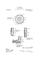
- Fig. 4 is a central longitudinal sectional view of a portion of the exhaust pipe, where disposed within the heating drum
- Fig. 5 is a detailed sectional'view of a modified form of'coupling used in connection with my device.
- Fig. 6 is a detailed View of a check valve used in connection with the supply pipe for 'thehot air, and
- FIG. 7 is a detailsectional view of my preferred form of coupling member, used in connection with the outlet pipe for the hot air.
- openings 16 therethrough adapted to permit the exhaust gases, in passing through the exhaust pipe, to escape therefrom, for a purpose to be hereinafter more fully described.
- the openings '16 may be disposed in any relation best adapted for this purpose, although I have preferablyshown the same as elongated longitudinally of the length of the pipe and disposed in staggered relatlon n such position, such openings belng also disposed inregistry with each other upon the diametrically opposite sides of the pipe, as is more clearly shown in Fig. 4 of the drawings. y
- any number of openings may be employed, so as to permit a --prope'r amount of the exhaust gases to escape therethrough, for thoroughly heating the air supply to a proper degree and in connection with the above it is also to be noted that I have shown three of such openings disposed in registry with a similar number of openings upon the opposite side of the pipe section and a pair of openings disposed intermediate the aforesaid openings and also upon the diametrically opposite sides of the pipe section, as in the other instance.
- a cylindrical casing 17 Mounted upon the pipe section 15 and with its forward end in abutment with the collar 14 is a cylindrical casing 17, the ends of said casing'being provided with the inturned flanges 18, one of which is in engage ment with the collar 14 as aforementioned said flanges being adapted to snugly fit upon thepipe section 15 at each end thereof, so as toprevent the escape of gases therefrom.
- Disposable'over the pipe sect-ion and casing is a cylindrical drum 20, the rear end 21 of I which, -comprisesa cap having the flange portion 22 which is interiorly screw threaded for engagement with the exteriorly screw threaded end of the, drum 20 and by which such parts are held securely together, said rear end or cap being snugly mounted upon the pipe section 15 outwardly of the rear in turned portion 18 of the casing 17 disposed thereon, said pipe section 15v being exteriorly screw threaded at its rear-end, whereby the interiorly screw threaded collar 23 may be adapted for securing acorrespondingly screw threaded pipe section 24:, which may be extended a suitable distance therefrom for the proper discharge of the exhaust gases or may be carried oif for any desired purpose.
- the forward end of the drum 20 has a cap 25 similarly secured thereto, as the cap 21 but said cap 25 is snugly mounted upon the casing 17, preferably to the rear of gases pass through said pipe, a suction will be created by the gases passing therethrough so as to keep a thorough circulation through the forward openings, into the easing and out of the rear openings 16 and prevent the gases from lagging within the intervening space, thereby insuring the thorough heating of the air supplied through the openings 26 within the drum 20.
- the carbureter or vaporizer 27 which has a suitable valve controlled connection with the engine cylinder.
- a second elbow joint 34 and apipe section 35 having connection with the carbureter is provided with a check valve for. automatically regulating the amount of air fed into the carbureter and adapted to be operated intermittently by the movement of the engine piston to its outward stroke at which time the supply of gas and air is sucked thereinto, for the next explosion by a suitable igniter, as is Well known in the art.
- This check valve comprises the head 36 which is seated against a shoulder 37 formed by the end of the pipe section 32, said head being adapted to be normally held against the shoulder by means of a coil spring 38 disposed around a curved-stemi39, rigidly secured to the head and extending through an opening 40 intermediate the ends of the elbow joint 34, said stein being provided with an operating head 41 if desired, which is removably secured thereto, so that the valve head and its attached stem and the spring may be removed through the openings at either end of the elbow joint.
- FIG. 5 of the drawings A further manner of detachably securing the pipe sections 28 and 29 is shown in Fig. 5 of the drawings, wherein said sections are provided with exteriorly screw threaded ends adapted to be coupled together by means of-an interiorly screw threaded collar or coupling member 42, so that by detaching the pipe section 29, the supply of warm air to the carbureter through the heating device may be cut off.
- said exhaust pipe having a plurality of openings therein adapted to discharge the exhaust gases within said space, a drum mounted upon said exhaust pipe at its rear end and provided with openings in its forward end through which air is adapted -to pass and be heated by the heat generated within the casing, an outlet for the drum, a carbureter having communication with the engine cylinder and connections between the outlet and carbureter for supplying heated air thereto.
- An internal combustion engine comprising the cylinder thereof having a suitable exhaust valve and a carbureter for supplying vaporized gases thereto, an exhaust pipe leading from said valve and comprising a short section of pipe provided with a plurality of openings, a casing carried by the pipe, a drum disposed thereon rearwardly of the forward end of the casing, said drum having a plurality of concentrically arranged openings in its forward end for the passage of air to be heated by the heat generated by the exhaust gases in the pipe and casing and valve connections between the drum at its rear end and the carbureter.
- an engine cylinder pro vided with an exhaust passage, an exhaust pipe detachably securedthereto, a casing disposed on said pipe, securing means at the forward and rear ends of said casing to prevent longitudinal movement thereof upon the pipe, said pipe having communication with the interior of the casing, a drum disposed upon the casing with its rear end mounted on the pipe rearwardly of the easing, said drum being adapted for the passage of air through its forward end, a carbureter for supplying a gaseous mixture to said cylinder, an oil supply therefor and detachable connections between the drum and the carbureter whereby the supply of air thereto may be regulated.
- a cylinder therefor, a carbureter for supplying a gaseous mixtureto said cylinder, an exhaust valve for said cylinder, an exhaust pipe leading from said valve, said pipe being provided with a plurality of openings disposed .in staggered relation longitudinally of its length, a casing snugly mounted around said pipe with an intervening space, theexhaust gases discharged through said pipe being adapted to pass through said inend of the drum and the carbureter and a tervening space to thoroughly heat said casvalve disposed in said connections and ing, a cylindrical drum snugly mounted upon adapted to automatically regulate the dissaid casing at its forward end and the eK- charge of heated air to the carbureter.
Landscapes
- Engineering & Computer Science (AREA)
- Chemical & Material Sciences (AREA)
- Combustion & Propulsion (AREA)
- Mechanical Engineering (AREA)
- General Engineering & Computer Science (AREA)
- Exhaust Gas After Treatment (AREA)
Description
E. H. BULLERT.
HOT AIR. INTAKE.
APPLICATION FILED MAR. 31, 1910.
ggfi gfi i Patented Mar.7,1911.
2 SHEETSSHEET l.
glwumrtoz- B. H. BULLERT.
HOT AIR INTAKE.
APPLICATION FILED MAR. 31, 1910.
Patented Mar. 7, 1911.
2 SHEETS-SHEET 2.
8440010504 HfiwZ/eri;
after/Hwy EDWARD H. CBULLERT, OF STEWART, MINNESOTA.
HOT-AIR INTAKE.
za'eaae'r.
Specification of Letters Patent.
PatentedMar. 7, 1911.
Application filed March 31, 1910. 'Serial No. 552,668.
the air supplied to the engine, so that the explosive mixture formed with the gasolene vapor, vwill be thoroughly vaporized, thereby =furnishing a most desirable mixture for deriving the greatest amount of power.
An object of this invention is to provide a novel'form of device or heater, so that the exhaust gases from the engine may be employed to thoroughly heat the supply of air before its passage into the carburetor, such mixture formed with the gasolene vapor be- I ing-thoroughly vaporized without any separate or previous heating of the gasolene on its way to the carburetor.
- Another object is to provide a construction which will be very simple and which can be applied to any gas engine of the usual form, without a great deal of expense for special fittings in applying the same, so that the device may be manufactured independent of theengineand afterward applied, thereby allowing the same to be attached to any engineof the ordinary type.
Another object isto provide means whereby 'the connection leading from the heater,
for supplying the air to the engine may be conveniently-detached, so that the device is rendered capable of ready use in cold weather, when it is desirable to heat the air supply but may be readily detached in warm weather when it is not desired to further" heat the 'air supply.
A still further object is to provide a suitable means for regulating the supply of heated air to the carbureter automatically, according to the amount of gasolene supplied in conjunction therewith.
Other objects and advantages will be aparent from the following description, and it will be understood -that changes in the specific structure shown and described may be made within the scope of the claims withline 33 of Fig. 2, Fig. 4 is a central longitudinal sectional view of a portion of the exhaust pipe, where disposed within the heating drum, Fig. 5 is a detailed sectional'view of a modified form of'coupling used in connection with my device. Fig. 6 is a detailed View of a check valve used in connection with the supply pipe for 'thehot air, and
adapted to regulate the supply to the carbureter of the engine, Fig. 7 is a detailsectional view of my preferred form of coupling member, used in connection with the outlet pipe for the hot air.
Referring to the drawings in detail, I have shown my improved heater as applied to' a gas engine 10, of the ordinary or any preferred type, which is provided with the" usual casing 11 of any desired form, though I have-shown the same as comprising a cylindrical extension disposed exteriorly of vby means of a sleevel is a short section of pipe 15, forming a continuation of said exhaust pipe, said short section 15 and the end of the exhaust pipe 13 "being exteriorly teriorly screw threaded port-ion of the sleeve 14, by which said parts are securely held in screw threaded for'engagement with the inposition. The short section of pipe 15 is.
provided with a. plurality of openings 16 therethrough adapted to permit the exhaust gases, in passing through the exhaust pipe, to escape therefrom, for a purpose to be hereinafter more fully described. The openings '16 may be disposed in any relation best adapted for this purpose, although I have preferablyshown the same as elongated longitudinally of the length of the pipe and disposed in staggered relatlon n such position, such openings belng also disposed inregistry with each other upon the diametrically opposite sides of the pipe, as is more clearly shown in Fig. 4 of the drawings. y
It is obvious that any number of openings may be employed, so as to permit a --prope'r amount of the exhaust gases to escape therethrough, for thoroughly heating the air supply to a proper degree and in connection with the above it is also to be noted that I have shown three of such openings disposed in registry with a similar number of openings upon the opposite side of the pipe section and a pair of openings disposed intermediate the aforesaid openings and also upon the diametrically opposite sides of the pipe section, as in the other instance. By the provision of such form of openmgs and the particular arrangement of the same, as
' setforth, it will be seen that since the exhaust gases are discharged through the pipe sectlon 15 under pressure of the engine piston on its-exhaust stroke, that sufficient heat will be generated by the escape of the gases through the openings by hayjng them somewhat elongated and. by having them disposed in staggered relation, the gases will not be allowed to escape under the explosive impulse, without passing through said openings and it will befurther apparent that all impurities will be thoroughly separated-from the gases and retained inthe pipe section, to be discharged upon the next exhaust of the engine, so that the escaping 4 gas for the heating of the air will be in the best condition for such heating purposes.
Mounted upon the pipe section 15 and with its forward end in abutment with the collar 14 is a cylindrical casing 17, the ends of said casing'being provided with the inturned flanges 18, one of which is in engage ment with the collar 14 as aforementioned said flanges being adapted to snugly fit upon thepipe section 15 at each end thereof, so as toprevent the escape of gases therefrom.
'whic'hpass through the openings 16 .and
into'the intervening space 19, between the casing 17 and the pipe 15.
"Dispomd'over the pipe sect-ion and casing is a cylindrical drum 20, the rear end 21 of I which, -comprisesa cap having the flange portion 22 which is interiorly screw threaded for engagement with the exteriorly screw threaded end of the, drum 20 and by which such parts are held securely together, said rear end or cap being snugly mounted upon the pipe section 15 outwardly of the rear in turned portion 18 of the casing 17 disposed thereon, said pipe section 15v being exteriorly screw threaded at its rear-end, whereby the interiorly screw threaded collar 23 may be adapted for securing acorrespondingly screw threaded pipe section 24:, which may be extended a suitable distance therefrom for the proper discharge of the exhaust gases or may be carried oif for any desired purpose. The forward end of the drum 20 has a cap 25 similarly secured thereto, as the cap 21 but said cap 25 is snugly mounted upon the casing 17, preferably to the rear of gases pass through said pipe, a suction will be created by the gases passing therethrough so as to keep a thorough circulation through the forward openings, into the easing and out of the rear openings 16 and prevent the gases from lagging within the intervening space, thereby insuring the thorough heating of the air supplied through the openings 26 within the drum 20. In order to carry off the warm or heated air from the drum to the carbureter or vaporizer 27, which has a suitable valve controlled connection with the engine cylinder. in order that the vaporized gas may be supplied thereto, I provide the rear end of the drumwith a leadoif formed of a short section of pipe. as shown at 28 and such section is secured to the surrounding wall or body portion of the drum in any suitable manner, though I have shown this section as being provided with. exterior screw threads adapted for engagement with an interiorly screw threaded aperture through the drum. As shown in Fig. 7 of the draw ings, the end of this pipe section28 outwardly of the drum is provided with a bev- Y eledsurface adapted to snugly'engage a correspondmgly formed end on a pipe section 29, such surfaces when in engagement,
being held in position by'mea ns of a collar 30 disposed snugly and slidably thereover and fully encompassing the same, it being apparent that should it be necessary todetach thepipe section 29, it is only necessary to slide the collar 30 upon either of the sections 28 or 2.9, whereupon the section 29, the elbow joint 31 and an extended portion.32 may be swung outwardly to disengage the coacting beveled surfaces.
In order to discharge the heated air into the carbureter, which is provided with a suitable supply pipe 33 for gasolene in a vaporized or-unvaporized state, I provide asecond elbow joint 34 andapipe section 35 having connection with the carbureter. The elbow 345 is provided with a check valve for. automatically regulating the amount of air fed into the carbureter and adapted to be operated intermittently by the movement of the engine piston to its outward stroke at which time the supply of gas and air is sucked thereinto, for the next explosion by a suitable igniter, as is Well known in the art. This check valve comprises the head 36 which is seated against a shoulder 37 formed by the end of the pipe section 32, said head being adapted to be normally held against the shoulder by means of a coil spring 38 disposed around a curved-stemi39, rigidly secured to the head and extending through an opening 40 intermediate the ends of the elbow joint 34, said stein being provided with an operating head 41 if desired, which is removably secured thereto, so that the valve head and its attached stem and the spring may be removed through the openings at either end of the elbow joint.
A further manner of detachably securing the pipe sections 28 and 29 is shown in Fig. 5 of the drawings, wherein said sections are provided with exteriorly screw threaded ends adapted to be coupled together by means of-an interiorly screw threaded collar or coupling member 42, so that by detaching the pipe section 29, the supply of warm air to the carbureter through the heating device may be cut off.
From the foregoing description, it is apparent that air supplied to the drum will be thoroughly heated in its passage through the drum and around the casing 17 by the exhaust gases passing through the casing 17,
'and will be supplied automatically to the carbureter as required through the medium of the check valve, thereby insuring a most desirable vaporization of the combustiblemixture and preventing the supply of gasolene to the engine cylinder; thusavoiding the formation of carbon within the cylinder and upon the supply valves, as has been found to be very objectionable, inasmuch as it interferes with the free operation thereof. Furthermore, the provision of the casing 17 disposed around the short pipe section 15 which is provided with the openings 16 to 'allow the exhaust gases to escape therethrough to heat the casing, permits said casing and the drum to'be manufactured of lighter or sheet material, for all useful purposes of the invention. It will also be noted,
that by having the collar 23 in engagement with the cap 21 at the rear end of the drum,
which cap is positioned against the flange 18 of the casing 17, the several parts are rigidly held in position and inasmuch as the exhaust pipe passes through the casing and drum,
a very desirable form of muffler and closed ends, said exhaust pipe having a plurality of openings therein adapted to discharge the exhaust gases within said space, a drum mounted upon said exhaust pipe at its rear end and provided with openings in its forward end through which air is adapted -to pass and be heated by the heat generated within the casing, an outlet for the drum, a carbureter having communication with the engine cylinder and connections between the outlet and carbureter for supplying heated air thereto.
2. An internal combustion engine comprising the cylinder thereof having a suitable exhaust valve and a carbureter for supplying vaporized gases thereto, an exhaust pipe leading from said valve and comprising a short section of pipe provided with a plurality of openings, a casing carried by the pipe, a drum disposed thereon rearwardly of the forward end of the casing, said drum having a plurality of concentrically arranged openings in its forward end for the passage of air to be heated by the heat generated by the exhaust gases in the pipe and casing and valve connections between the drum at its rear end and the carbureter.
3. In combination, an engine cylinder pro vided with an exhaust passage, an exhaust pipe detachably securedthereto, a casing disposed on said pipe, securing means at the forward and rear ends of said casing to prevent longitudinal movement thereof upon the pipe, said pipe having communication with the interior of the casing, a drum disposed upon the casing with its rear end mounted on the pipe rearwardly of the easing, said drum being adapted for the passage of air through its forward end, a carbureter for supplying a gaseous mixture to said cylinder, an oil supply therefor and detachable connections between the drum and the carbureter whereby the supply of air thereto may be regulated.
4. In an internal combustion engine, a cylinder therefor, a carbureter for supplying a gaseous mixtureto said cylinder, an exhaust valve for said cylinder, an exhaust pipe leading from said valve, said pipe being provided with a plurality of openings disposed .in staggered relation longitudinally of its length, a casing snugly mounted around said pipe with an intervening space, theexhaust gases discharged through said pipe being adapted to pass through said inend of the drum and the carbureter and a tervening space to thoroughly heat said casvalve disposed in said connections and ing,a cylindrical drum snugly mounted upon adapted to automatically regulate the dissaid casing at its forward end and the eK- charge of heated air to the carbureter.
5 haust pipe at its rear end, said drum hav- In testimony whereof I aflix my signature, 15-
ing a plurality of openings arranged conin presence of two witnesses. centrically through its forward end and EDVARD H. BULLERT. adapted to permit the passage of air through \Vitnesses: the drum to be heated by its passage around I FRED REESE, lol the casing, )ipe connections between the rear L. S. RICHARDS.
Priority Applications (1)
| Application Number | Priority Date | Filing Date | Title |
|---|---|---|---|
| US55266810A US986357A (en) | 1910-03-31 | 1910-03-31 | Hot-air intake. |
Applications Claiming Priority (1)
| Application Number | Priority Date | Filing Date | Title |
|---|---|---|---|
| US55266810A US986357A (en) | 1910-03-31 | 1910-03-31 | Hot-air intake. |
Publications (1)
| Publication Number | Publication Date |
|---|---|
| US986357A true US986357A (en) | 1911-03-07 |
Family
ID=3054698
Family Applications (1)
| Application Number | Title | Priority Date | Filing Date |
|---|---|---|---|
| US55266810A Expired - Lifetime US986357A (en) | 1910-03-31 | 1910-03-31 | Hot-air intake. |
Country Status (1)
| Country | Link |
|---|---|
| US (1) | US986357A (en) |
-
1910
- 1910-03-31 US US55266810A patent/US986357A/en not_active Expired - Lifetime
Similar Documents
| Publication | Publication Date | Title |
|---|---|---|
| US2896658A (en) | Regulator-vaporizer for a liquefied gas carburetion system | |
| US986357A (en) | Hot-air intake. | |
| US1051690A (en) | Internal-combustion engine. | |
| US1370459A (en) | Auxiliary air-inlet for engines | |
| US1359079A (en) | Auxiliary air-valve | |
| US1366530A (en) | Oil-engine | |
| US1487234A (en) | Carburetor | |
| US2124504A (en) | Carburetor choke control mechanism | |
| US1190592A (en) | Manifold for gas-engines. | |
| US1257089A (en) | Fuel-vaporizing device for internal-combustion engines. | |
| US1217233A (en) | Carbureter attachment for internal-combustion engines. | |
| US1429770A (en) | Auxiliary air intake for internal-combustion engines | |
| US1211087A (en) | Means for converting kerosene-oil into explosive gas for internal-combustion engines. | |
| US1250382A (en) | Vaporizing apparatus for internal-combustion engines. | |
| US1357039A (en) | Hydropneumatic fuel-mixing apparatus | |
| US1141450A (en) | Device for supplying heated air to carbureters. | |
| US2353926A (en) | Gas generating apparatus | |
| US633319A (en) | Carbureter. | |
| US1215027A (en) | Fuel-vaporizer for internal-combustion engines. | |
| US1519013A (en) | Vaporizing device for internal-combustion engines | |
| US1143902A (en) | Gaseous-fuel heater and mixer for internal-combustion engines. | |
| US1624623A (en) | Art of supplying fuel to explosive engines | |
| US756879A (en) | Carbureter for internal-combustion engines. | |
| US1926449A (en) | Duplex gasifier, feeder, and regulator for internal combustion engines | |
| US1453669A (en) | Engine preheater |