US9861377B2 - Unfocused electrohydraulic lithotripter - Google Patents
Unfocused electrohydraulic lithotripter Download PDFInfo
- Publication number
- US9861377B2 US9861377B2 US14/852,051 US201514852051A US9861377B2 US 9861377 B2 US9861377 B2 US 9861377B2 US 201514852051 A US201514852051 A US 201514852051A US 9861377 B2 US9861377 B2 US 9861377B2
- Authority
- US
- United States
- Prior art keywords
- probe
- distal end
- probes
- electrohydraulic
- electrode
- Prior art date
- Legal status (The legal status is an assumption and is not a legal conclusion. Google has not performed a legal analysis and makes no representation as to the accuracy of the status listed.)
- Active, expires
Links
Images


Classifications
-
- A—HUMAN NECESSITIES
- A61—MEDICAL OR VETERINARY SCIENCE; HYGIENE
- A61B—DIAGNOSIS; SURGERY; IDENTIFICATION
- A61B17/00—Surgical instruments, devices or methods, e.g. tourniquets
- A61B17/22—Implements for squeezing-off ulcers or the like on the inside of inner organs of the body; Implements for scraping-out cavities of body organs, e.g. bones; Calculus removers; Calculus smashing apparatus; Apparatus for removing obstructions in blood vessels, not otherwise provided for
- A61B17/22004—Implements for squeezing-off ulcers or the like on the inside of inner organs of the body; Implements for scraping-out cavities of body organs, e.g. bones; Calculus removers; Calculus smashing apparatus; Apparatus for removing obstructions in blood vessels, not otherwise provided for using mechanical vibrations, e.g. ultrasonic shock waves
- A61B17/22012—Implements for squeezing-off ulcers or the like on the inside of inner organs of the body; Implements for scraping-out cavities of body organs, e.g. bones; Calculus removers; Calculus smashing apparatus; Apparatus for removing obstructions in blood vessels, not otherwise provided for using mechanical vibrations, e.g. ultrasonic shock waves in direct contact with, or very close to, the obstruction or concrement
- A61B17/22022—Implements for squeezing-off ulcers or the like on the inside of inner organs of the body; Implements for scraping-out cavities of body organs, e.g. bones; Calculus removers; Calculus smashing apparatus; Apparatus for removing obstructions in blood vessels, not otherwise provided for using mechanical vibrations, e.g. ultrasonic shock waves in direct contact with, or very close to, the obstruction or concrement using electric discharge
-
- A—HUMAN NECESSITIES
- A61—MEDICAL OR VETERINARY SCIENCE; HYGIENE
- A61B—DIAGNOSIS; SURGERY; IDENTIFICATION
- A61B17/00—Surgical instruments, devices or methods, e.g. tourniquets
- A61B17/22—Implements for squeezing-off ulcers or the like on the inside of inner organs of the body; Implements for scraping-out cavities of body organs, e.g. bones; Calculus removers; Calculus smashing apparatus; Apparatus for removing obstructions in blood vessels, not otherwise provided for
- A61B17/22004—Implements for squeezing-off ulcers or the like on the inside of inner organs of the body; Implements for scraping-out cavities of body organs, e.g. bones; Calculus removers; Calculus smashing apparatus; Apparatus for removing obstructions in blood vessels, not otherwise provided for using mechanical vibrations, e.g. ultrasonic shock waves
- A61B17/22012—Implements for squeezing-off ulcers or the like on the inside of inner organs of the body; Implements for scraping-out cavities of body organs, e.g. bones; Calculus removers; Calculus smashing apparatus; Apparatus for removing obstructions in blood vessels, not otherwise provided for using mechanical vibrations, e.g. ultrasonic shock waves in direct contact with, or very close to, the obstruction or concrement
- A61B2017/22025—Implements for squeezing-off ulcers or the like on the inside of inner organs of the body; Implements for scraping-out cavities of body organs, e.g. bones; Calculus removers; Calculus smashing apparatus; Apparatus for removing obstructions in blood vessels, not otherwise provided for using mechanical vibrations, e.g. ultrasonic shock waves in direct contact with, or very close to, the obstruction or concrement applying a shock wave
-
- A—HUMAN NECESSITIES
- A61—MEDICAL OR VETERINARY SCIENCE; HYGIENE
- A61B—DIAGNOSIS; SURGERY; IDENTIFICATION
- A61B17/00—Surgical instruments, devices or methods, e.g. tourniquets
- A61B17/22—Implements for squeezing-off ulcers or the like on the inside of inner organs of the body; Implements for scraping-out cavities of body organs, e.g. bones; Calculus removers; Calculus smashing apparatus; Apparatus for removing obstructions in blood vessels, not otherwise provided for
- A61B17/22004—Implements for squeezing-off ulcers or the like on the inside of inner organs of the body; Implements for scraping-out cavities of body organs, e.g. bones; Calculus removers; Calculus smashing apparatus; Apparatus for removing obstructions in blood vessels, not otherwise provided for using mechanical vibrations, e.g. ultrasonic shock waves
- A61B2017/22027—Features of transducers
- A61B2017/22028—Features of transducers arrays, e.g. phased arrays
Definitions
- the present disclosure relates to electrohydraulic lithotripters, and in particular, an unfocused electrohydraulic lithotripter.
- Electrohydraulic lithotripsy both intracorporeal (“IEHL”) and extracorporeal (“ESWL”), has been used in the medical field, primarily for breaking concretions in the urinary or biliary track.
- Conventional ESWL lithotripsy produces a focused or reflected shockwave that radiates axially from a distal end of the lithotripsy electrode.
- This form of treatment has been adapted for generating a shockwave projected to a specific spot within an organism, or at the surface of an organism.
- Those adaptations utilize various wave shaping methods, usually in the form of elliptical reflection, to project the maximum power to a focal point inside an organism or on the surface of an organism.
- the focal point receives the largest impact from the shockwave, with degradation in the strength of the shockwave taking the form of an hourglass-type shape on both sides of the focal point, the largest impact occurring at the narrowest part of the hourglass shape.
- an electrohydraulic lithotripter in one aspect includes a plurality of electrohydraulic probes.
- Each probe of the plurality of probes has a first electrode and a second electrode positioned at a distal end of the probe such that when the probe is discharged in a fluid environment, an electric arc between the first electrode and the second electrode produces a shockwave that radiates from the distal end of the probe.
- a first probe and a second probe of the plurality of probes are configured to discharge simultaneously.
- a distal end of the first probe and a distal end of the second probe may be positioned in a plane.
- a distal end of the first probe may be positioned in a first plane and a distal end of the second probe may be positioned in a second plane, where the first plane is different than the second plane.
- the electrohydraulic lithotripter includes a third probe.
- a central axis of the first probe, a central axis of the second probe, and a central axis of the third probe may not all be positioned in a same plane.
- the first probe, the second probe, and the third probe may be configured to discharge simultaneously.
- an electrohydraulic lithotripter in another aspect, includes a plurality of electrohydraulic probes.
- Each probe of the plurality of probes has a first electrode and a second electrode positioned at a distal end of the probe such that when the probe is discharged in a fluid environment, an electric arc between the first electrode and the second electrode produces a shockwave that radiates from the distal end of the probe.
- a first probe and a second probe of the plurality of probes are configured to discharge sequentially.
- a distal end of the first probe and a distal end of the second probe may be aligned in a plane.
- a distal end of the first probe may be positioned in a first plane and a distal end of the second probe may be positioned in a second plane, where the first plane is different than the second plane.
- the electrohydraulic lithotripter includes a third probe.
- a central axis of the first probe, a central axis of the second probe, and a central axis of the third probe may not all be positioned in a same plane.
- the first probe, the second probe, and the third probe may be configured to discharge sequentially.
- an electrohydraulic lithotripter includes at least one electrohydraulic probe.
- Each probe of the at least one probe has a first electrode and a second electrode positioned at a distal end of the probe, such that when the probe is discharged in a fluid environment, an electric arc between the first electrode and the second electrode produces a shockwave that radiates from the distal end of the probe.
- a flexible encapsulating member at least partially surrounds the distal end of each probe of the at least one probe.
- a plate positioned relative to the distal end of each probe of the at least one probe receives the shockwave that radiates from the distal end of each probe.
- the plate may be positioned within the flexible encapsulating member.
- the plate may be positioned outside the flexible encapsulating member, in which case, the plate may be coated with a medicament.
- the plate may include at least one opening.
- the plate may be formed of a rigid material.
- the plate may be formed of a flexible material.
- the at least one probe includes two or more probes.
- an electrohydraulic lithotripter for extracorporeal administration of electrohydraulic lithotripsy includes at least one electrohydraulic probe.
- Each probe of the at least one probe has a first electrode and a second electrode positioned at a distal end of the probe, such that when the probe is discharged in a fluid environment, an electric arc between the first electrode and the second electrode produces an unfocused shockwave that radiates from the distal end of the probe.
- the electrohydraulic lithotripter may be characterized by the absence of a flexible encapsulating member at least partially surrounding the distal end of each probe of the at least one probe.
- the electrohydraulic lithotripter may further include a flexible encapsulating member extracorporeally positionable against a tissue, the flexible encapsulating member at least partially surrounding the distal end of each probe of the at least one probe.
- the at least one probe comprises a first probe and a second probe.
- the first probe and the second probe may be configured to discharge simultaneously, or the first probe and the second probe are configured to discharge sequentially.
- FIG. 1A is a perspective view of an electrohydraulic lithotripter having a single electrohydraulic probe
- FIG. 1B is a perspective view of the electrohydraulic lithotripsy probe of FIG. 1A , shown without the flexible encapsulating member;
- FIG. 1C is a cross-sectional view of the tip of the electrohydraulic lithotripsy probe of FIG. 1B ;
- FIG. 2A is a perspective view of a second embodiment of an electrohydraulic lithotripter having two electrohydraulic probes;
- FIG. 2B is a perspective view of the electrohydraulic lithotripsy probes of FIG. 2A , shown without the flexible encapsulating member;
- FIG. 3A is a perspective view of a third embodiment of an electrohydraulic lithotripter having three electrohydraulic probes;
- FIG. 3B is a perspective view of the electrohydraulic lithotripsy probes of FIG. 3A , shown without the flexible encapsulating member;
- FIG. 4A is a perspective view of a fourth embodiment of an electrohydraulic lithotripter having four electrohydraulic probes;
- FIG. 4B is a perspective view of the electrohydraulic lithotripsy probes of FIG. 4A , shown without the flexible encapsulating member;
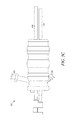
- FIG. 5A is a perspective view of a fifth embodiment of an electrohydraulic lithotripter having five electrohydraulic probes
- FIG. 5B is a perspective view of the electrohydraulic lithotripsy probes of FIG. 5A , shown without the flexible encapsulating member;
- FIG. 5C is a side view of the electrohydraulic lithotripsy probes of FIG. 5B ;
- FIGS. 6A-D are illustrations of the wave shapes and patterns achievable by the disclosed embodiments.
- FIGS. 7A-C are exemplary illustrations of a plate useable with any of the embodiments described herein;
- FIGS. 8A-E are various perspective and side views of an alternatively shaped lithotripsy probe tip
- FIG. 9 is an illustration of another alternatively shaped lithotripsy probe tip.
- FIG. 10 is an illustration of another alternatively shaped lithotripsy probe tip.
- EHL probes include a first electrode and a second electrode positioned at a distal end of the probe.
- a difference in voltage polarities between the first and second electrodes causes an electric arc, resulting in a shockwave that radiates from the lithotripsy probe.
- the shockwave may be focused toward a specific region of tissue.
- unfocused EHL is accomplished by using at least one, and in some cases two or more, EHL probes.
- the administration of unfocused EHL may be advantageous, for example, in the creation of various shockwave strengths, wave front sizes, wave shapes, or to vary the frequency of shockwaves, as desired, for the treatment of tissues.
- Such treatments could range, for example, from lightly “massaging” a tissue, to tissue oblation, or cellular disturbance, and potential cellular modification. Areas that may benefit from this treatment could include, for example, tumors, decubitus ulcers, wounds, bone spurs, calcium deposits, arthritic areas, etc.
- the EHL probes described below may be delivered to a proper channel of a heart by threading (or pre-loading) the EHL probes through a center lumen of a catheter or balloon device.
- the catheter may be threaded through appropriate veins or arteries to address concretion either forming in vessels or even in the valves of the heart or other organs.
- the EHL probes described below may be delivered to a small lumen of a body organ for the purpose of disturbing or disrupting (distressing) tissue of the body organ in such a way as to cause a stricture or a “scarring” of the tissue for the purpose of creating a permanent stricture or blockage of the lumen.
- the EHL probes described below may be used extracorporeally, for example, by positioning a fluid-filled encapsulating member that encapsulates the EHL probe(s) in contact with the tissue to be treated, or by placing the target tissue (e.g., a bone spur on a foot) and the EHL probe(s) in a fluid-filled basin.
- tissue to be treated e.g., a bone spur on a foot
- target tissue e.g., a bone spur on a foot
- the electrohydraulic lithotripter 100 includes an EHL probe 110 having a lithotripsy probe tip 101 , an insulating body 102 , a first electrode 104 , and a second electrode 106 .
- the first electrode 104 , the second electrode 106 , or both includes an electrically conductive material such as copper, silver, or stainless steel.
- the first electrode 104 and the second electrode 106 of the EHL probe 110 are cylindrical, with the second electrode 106 concentrically aligned with first electrode 104 .
- An insulating material 107 is disposed in the annular gap formed between the first electrode 104 and the second electrode 106 .
- the distal end of the first electrode 104 is annular, whereas the distal end of the second electrode 106 is circular.
- other EHL probes having electrodes of different shapes and orientations may also be used without departing from the concepts described herein.
- a probe may include an electrode comprised of an array of conductive elements.
- the first electrode 104 is electrically coupled with a first electrically conductive structure (not shown) in the EHL probe 110 .
- the first electrically conductive structure may be coupled with an electrical source, such as an electrohydraulic generator (Autolith, Supplied by Northgate Technologies Inc.), used to charge the first electrode 104 to a first polarity.
- the second electrode 106 is electrically coupled with a second electrically conductive structure 116 in the EHL probe 110 .
- the second electrically conductive structure 116 may be coupled with an electrical source and used to charge the second electrode 106 to a second polarity, which is opposite to the first polarity of the first electrode 104 .
- the first electrode 104 is an anode and the second electrode 106 is a cathode, wherein in other implementations, the first electrode 104 is a cathode and the second electrode 106 is an anode.
- a single anode may be used with multiple cathodes, or conversely, a single cathode may be used with multiple anodes.
- first electrode 104 When the first electrode 104 is charged to a first polarity via the first conductive structure and the second electrode 106 is charged to a second, opposite polarity via the second conductive structure 116 , a discharge of electricity occurs between the first electrode 104 and the second electrode 106 (an electric arc) when the potential between the first electrode 104 and the second electrode 106 reaches the breakdown voltage for the media separating the electrodes.
- a flexible encapsulating member 118 such as a balloon, comprising a water-tight flexible material, such as Mylar.
- the flexible encapsulating member 118 encapsulates a liquid, such as saline.
- other liquids can be used. In general, the less ionic content of the fluid, the greater the breakdown voltage, and the stronger the shockwave, whereas the greater the ionic content, the less the breakdown voltage, and the weaker the shockwave.
- a flexible encapsulating member 118 does not surround the EHL probe tip 101 , for example, when the EHL probe 100 is used intracorporeally within a fluid-filled body cavity, or when the EHL probe 100 is used extracorporeally, such as in a fluid-filled basin.
- the electrohydraulic lithotripter 200 includes a first EHL probe 210 and a second EHL probe 220 .
- the first EHL probe 210 and the second EHL probe 220 may be constructed and operate in the same manner as describe above with regards to the EHL probe 110 , although it is envisioned that other EHL probes having electrodes of different shapes and orientations may also be used without departing from the concepts described herein.
- the first EHL probe 210 and the second EHL probe 220 may be connected together by a band 205 .
- the distal ends of the first EHL probe 210 and the second EHL probe 220 are aligned, i.e., they lie in the same plane. In other implementations, the distal ends lie in different planes.
- a flexible encapsulating member 218 surrounds a distal end of the electrohydraulic lithotripter 200 . In other implementations, a flexible encapsulating member 218 does not surround a distal end of the electrohydraulic lithotripter 200 .
- the electrohydraulic lithotripter 300 includes a first EHL probe 310 , a second EHL probe 320 , and a third EHL probe 330 .
- the first EHL probe 310 , the second EHL probe 320 , and the third EHL probe 330 may be constructed and operate in the same manner as describe above with regards to the EHL probe 110 , although it is envisioned that other EHL probes having electrodes of different shapes and orientations may also be used without departing from the concepts described herein.
- the first EHL probe 310 , the second EHL probe 320 , and the third EHL probe 330 may be connected together by a band 305 .
- the distal ends of the first EHL probe 310 , the second EHL probe 320 , and the third EHL probe 330 are aligned, i.e., they lie in the same plane. In other implementations, the distal ends lie in different planes. Also as shown in this embodiment, the first EHL probe 310 , the second EHL probe 320 , and the third EHL probe 330 are arranged such that their axes lie in the same plane. In other implementations, their axis are offset, for example, in a triangular configuration. Furthermore, as shown in this embodiment, a flexible encapsulating member 318 surrounds a distal end of the electrohydraulic lithotripter 300 . In other implementations, a flexible encapsulating member 318 does not surround a distal end of the electrohydraulic lithotripter 300 .
- the electrohydraulic lithotripter 400 includes a first EHL probe 410 , a second EHL probe 420 , a third EHL probe 430 , and a fourth EHL probe 440 .
- the first EHL probe 410 , the second EHL probe 420 , the third EHL probe 430 , and the fourth EHL probe 440 may be constructed and operate in the same manner as describe above with regards to the EHL probe 110 , although it is envisioned that other EHL probes having electrodes of different shapes and orientations may also be used without departing from the concepts described herein.
- the first EHL probe 410 , the second EHL probe 420 , the third EHL probe 430 , and the fourth EHL probe 440 may be connected together by a band 405 .
- the distal ends of the first EHL probe 410 , the second EHL probe 420 , the third EHL probe 430 , and the fourth EHL probe 440 are aligned, i.e., they lie in the same plane. In other implementations, the distal ends lie in different planes. Also as shown in this embodiment, the first EHL probe 410 and the fourth EHL probe 440 are arranged such that their axes lie in the same plane, while the second EHL probe 420 and the third EHL probe 430 are arranged such that their axes lie in the same plane. In other implementations, all axes may lie in the same plane, or they may be arranged, for example, in a square configuration.
- a flexible encapsulating member 418 surrounds a distal end of the electrohydraulic lithotripter 400 .
- a flexible encapsulating member 418 does not surround a distal end of the electrohydraulic lithotripter 400 .
- the electrohydraulic lithotripter 500 includes a first EHL probe 510 , a second EHL probe 520 , a third EHL probe 530 , a fourth EHL probe 540 , and a fifth EHL probe 550 .
- the first EHL probe 510 , the second EHL probe 520 , the third EHL probe 530 , the fourth EHL probe 540 , and the fifth EHL probe 550 may be constructed and operate in the same manner as describe above with regards to the EHL probe 110 , although it is envisioned that other EHL probes having electrodes of different shapes and orientations may also be used without departing from the concepts described herein.
- the first EHL probe 510 , the second EHL probe 520 , the third EHL probe 530 , the fourth EHL probe 540 , and the fifth EHL probe 550 may be connected together by a band 505 .
- the distal ends of the first EHL probe 510 and the third EHL probe 530 are aligned, i.e., they lie in the same plane, whereas the distal ends of the second EHL probe 520 , the fourth EHL probe 540 , and the fifth EHL probe 550 are aligned. In other implementations, the distal ends of all probes lie in the same plane. Also as shown in this embodiment, the first EHL probe 510 and the third EHL probe 530 are arranged such that their axes lie in the same plane, whereas the second EHL probe 520 , the fourth EHL probe 540 , and the fifth EHL probe 550 are arranged such that their axes lie in the same plane.
- all axes may lie in the same plane, or they may be arranged, for example, in a circular configuration.
- a flexible encapsulating member 518 surrounds a distal end of the electrohydraulic lithotripter 500 . In other implementations, a flexible encapsulating member 518 does not surround a distal end of the electrohydraulic lithotripter 500 .
- the electrohydraulic lithotripter 500 may include a first channel (or lumen) 560 and a second channel (or lumen) 570 that are each in communication with an interior of the flexible encapsulating member 518 .
- a first channel (or lumen) and a second channel (or lumen) in communication with an interior of a flexible encapsulating member may be included in any of the embodiments described herein.
- the first channel 520 may be utilized to infuse a liquid, such as saline, into an interior of the flexible encapsulating member 518 for the purpose of expanding the flexible encapsulating member 518 and providing a medium for creating electrohydraulic effect.
- the second channel 570 may be utilized to remove the liquid from the interior of the flexible encapsulating member 518 and collapse the flexible encapsulating member 518 .
- the second channel 570 may further be utilized to degass the fluid within the flexible encapsulating member 518 after an electrohydraulic discharge between electrodes.
- the circulation of fluid through the interior of the flexible encapsulating member 518 using the first and second channels 560 , 570 may be done through manual means such as a syringe, mechanical means such as a pump, or any other means known in the art.
- the first and/or second channels 560 , 570 may include one or more valves, membranes, or cartridges to assist in injecting a fluid into the interior region of the flexible encapsulating member 518 , removing a fluid from the interior region of the flexible encapsulating member 518 , or degassing the fluid within the interior region of the flexible encapsulating member 518 .
- a valve or membrane positioned in or adjacent to the first channel 560 may allow a fluid to flow into the interior region of the flexible encapsulating member 518 while preventing the fluid from entering the first channel 560 from the interior region of the flexible encapsulating member 518 .
- a valve or membrane positioned in or adjacent to the second channel 570 may allow a fluid to flow out of the interior region of the flexible encapsulating member 518 while preventing fluid from exiting the second channel 570 and flowing into the interior of the flexible encapsulating member 518 .
- a membrane or cartridge may be positioned in or adjacent to the second channel 570 to assist in degassing fluid within the interior region of the flexible encapsulating member 518 .
- valves that may be utilized include one-way valves produced by Qosina Corp or Value Plastics.
- membranes, such as semipermeable membranes, that may be utilized include those produced by W.L. Gore & Associates, Inc.
- Each of the previously described embodiments may be used to provide unfocused EHL.
- the activation of individual EHL probes creates unfocused shockwaves radiating from each probe.
- an almost infinite number of shockwave patterns may be generated.
- Such patterns can be used, for example, to create larger wave fronts than a single probe, stronger shockwaves, and different wave shapes.
- the probes may be fired or discharged simultaneously, or in sequences, or at various frequencies.
- the arrangement of probes may be such that distal ends of the probes are staggered, or arranged in different planes, thereby creating additional wave shapes or patterns.
- a generator may be set to fire or discharge a particular EHL probe at varying power and at varying frequencies.
- One suitable generator is the Autolith, supplied by Northgate Technologies, Inc.
- Other suitable generators are shown and described in U.S. Provisional Patent Application No. 61/684,353, the entirety of which is herein incorporated by reference.
- the device could use different capacitors and switching techniques to change the output of a particular EHL probe, or probes. Redundant circuitry could be also be used if necessary to discharge a large number of probes simultaneously, or in specific sequences, or in patterns, depending on the desired treatment.
- FIGS. 6A-6D illustrate some of the wave shapes and patterns achievable by the previously described embodiments.
- the EHL probes of the electrohydraulic lithotripter 200 may be fired or discharged simultaneously, thereby producing a wave front having an increased sized.
- the probes of the electrohydraulic lithotripter 200 may be fired or discharged sequentially to create an alternating waveform.
- the EHL probes of the electrohydraulic lithotripter 300 may be fired or discharged simultaneously, thereby producing a wave front having an even larger size.
- FIG. 6A illustrate some of the wave shapes and patterns achievable by the previously described embodiments.
- the EHL probes of the electrohydraulic lithotripter 200 may be fired or discharged simultaneously, thereby producing a wave front having an increased sized.
- the probes of the electrohydraulic lithotripter 200 may be fired or discharged sequentially to create an alternating waveform.
- the EHL probes of the electrohydraulic lithotripter 300 may be fired or
- the EHL probes of the electrohydraulic lithotripter 300 may be fired or discharged sequentially, thereby creating a cascading waveform. It will be appreciated that additional wave shapes and patterns may be achieved by applying the same firing or discharge concepts to the other embodiments described herein.
- additional wave strengths, shapes, and patterns may be generated by altering the shapes and orientations of electrodes within individual EHL probes of a particular embodiment of an electrohydraulic lithotripter, for example, by changing the probe dimensions, such as the annular gap between the first electrode and the second electrode.
- the strength of the shockwave(s) delivered to a tissue may be selectively adjusted by changing the volume of fluid in the flexible encapsulating member. Because the strength of a shockwave delivered to a tissue is dependent on the distance from the distal end of the EHL probe(s) to the tissue, the strength of a shockwave may be increased or decreased by increasing or decreasing the volume of the fluid in the flexible encapsulating member. These embodiments may also include means for measuring the distance between the distal ends of individual EHL probe(s) and the flexible encapsulating member.
- the strength of the shockwave(s) delivered to a tissue may be selectively adjusted by axially repositioning particular EHL probes within the electrohydraulic lithotripter.
- the electrohydraulic lithotripter 400 includes a first EHL probe 410 , a second EHL probe 420 , a third EHL probe 430 , and a fourth EHL probe 440 .
- the EHL probes are connected together by a band 405 .
- the distal ends of the first EHL probe 410 , the second EHL probe 420 , the third EHL probe 430 , and the fourth EHL probe 440 are aligned, i.e., they lie in the same plane.
- a user may axially advance, for example, the first EHL probe 410 and the fourth EHL probe 440 , relative to the band 405 , the second EHL probe 420 , and the third EHL probe 430 , such that the distal ends of the first EHL probe 410 and the fourth EHL probe 440 lie in a different plane than the distal ends of the second EHL probe 420 and the third EHL probe 430 .
- These embodiments may also include means for locking the positions of the EHL probes relative to one another.
- the shockwave(s) may be discharged toward a conductive surface, such as a pad or a plate, for purposes of transferring the shockwave to particular tissues areas.
- a plate may be used to distribute or spread the shockwave over the surface of the plate.
- a plate having a number of openings may be used to focus the discharged shockwave(s) through the openings to treat a targeted tissue area.
- Such a plate may be made of either flexible or rigid materials, depending on the desired shockwave deflection, absorption, or transfer characteristics, and can be positioned either inside or outside of the flexible encapsulating member. If positioned on the outside of the flexible encapsulating member, the plate may be coated or infused with a medication to assist in the tissue treatment.
- FIGS. 7A-7C are exemplary illustrations of a plate 700 useable with any of the embodiments described herein.
- the plate 700 may have a single, centrally positioned opening 701 intended to allow the shockwave(s) discharged from the EHL probe(s) to pass therethrough.
- the plate 700 may include a plurality of openings 701 , aligned with the EHL probes of the associated electrohydraulic lithotripter, for example, the five EHL probes of the electrohydraulic lithotripter 500 .
- the plate 700 may include a plurality of openings in an arrangement, for example, intended to diffuse the shockwave(s) discharged from the EHL probe(s). Alternatively, the plate may not have any openings.
- endoscopes that are designed to reach more remote locations in the body have presented various difficulties in trying to reach these areas of the body.
- endoscopes and other instruments such as electrohydraulic lithotripsy probes, may have to maneuver through extremely tortuous paths to conduct diagnostic and operating procedures. For example, bends as sharp as 90 degrees, and in some instances, as much as 120 degrees or more, must be traversed to reach the desired location.
- the tip of these devices is usually shaped as a square, or includes beveled edges, which have been insufficient to prevent lodging, kinking, or resistance caused from too much friction, to progress past or through the tortuous angles, thereby rendering it impossible in some cases for the laser fibers or electrohydraulic lithotripsy probes to reach the target area.
- Some approaches to obviate these problems have included increasing the size and stiffness of the fiber or probe, covering the probe with more lubricious materials (e.g., Teflon), applying a hydrophilic coating to the probe, and sever beveling of the fiber or probe tip. While these techniques have led to improvement, they have not solved the problem sufficiently.
- more lubricious materials e.g., Teflon
- FIGS. 8A-E various perspective and side views of an alternatively shaped lithotripsy probe tip 718 are shown.
- the lithotripsy probe tip 718 is disposed on the end of an insulating body 702 of an electrohydraulic lithotripter.
- the lithotripsy probe tip 718 may be utilized in place of any of the previously described lithotripsy probe tips, as well as in other electrohydraulic lithotripters.
- the lithotripsy probe tip 718 is adapted to improve the delivery of an electrohydraulic lithotripter to a remote location in the body. As shown, the lithotripsy probe tip 718 is spherically shaped. Significantly, the distal surface of the lithotripsy probe tip 718 essentially presents a “round surface” to the structural areas it may contact. All of the previous improvements (e.g., stiffer shafts, slippery sheaths, hydrophilic coatings, etc.) could be included and used in conjunction with the improved tip shape.
- the diameter of the spherically shaped lithotripsy probe tip 718 is approximately 1.5 mm (0.585 inches) or less, as that is approximately the largest lumen diameter currently in use in endoscopes used in urology or gastrointestinal applications.
- the diameter could be as small as 0.5 mm for some applications.
- the tip size could be larger or smaller depending on the available lumen, endoscope, or body area being accessed. Ultimately, the size of the tip would be governed by the lumen size through which it is threaded.
- the shape of the tip could be any other rounded shape, including, for example, a “donut” shape, as shown in FIG. 9 .
- the “donut” shaped tip could, for example, have a radius of about 0.018 inches, a diameter of 0.036 inches, an axial length of 0.025 inches, and an inner lumen diameter of 0.008 inches.
- the shape of the tip could be a bead shape having a spherical head with flat or cylindrical sides, as shown in FIG. 10 .
- the bead shaped tip could, for example, have a radius of about 0.026 inches in the spherical head, a diameter of 0.05 inches in the cylindrical sides, an axial length of 0.052 inches, and an inner lumen diameter of 0.028 inches. General tolerances for these dimensions above could range between +/ ⁇ 0.003 to 0.005 inches. It should be appreciated that so long as the lead surfaces of the tip present a “round” surface for contacting the lumen, just about any shape may be used.
- lithotripsy probe tips described above may be constructed of many types of materials, preferably metal, plastic, or glass. Depending on the material used, the tip may be integral to the function of the device (such as glass in a laser fiber, or metal in a lithotripsy probe tip), or could be added on to and/or bonded on an existing tip design.
Abstract
Electrohydraulic lithotripters comprising a plurality of electrohydraulic probes are disclosed. Each probe of the plurality of probes comprise a first electrode and a second electrode positioned at a distal end of the probe such that when the probe is discharged, an electric arc between the first electrode and the second electrode produces a shockwave that radiates from the distal end of the probe. A first probe and a second probe of the plurality of probes may be configured to discharge simultaneously or sequentially.
Description
This application is a continuation of International Application No. PCT/IB2014/000275, filed on Mar. 10, 2014, pending, which claims the benefit of U.S. Provisional Application No. 61/775,907, filed on Mar. 11, 2013, both of which are incorporated herein by reference.
The present disclosure relates to electrohydraulic lithotripters, and in particular, an unfocused electrohydraulic lithotripter.
Electrohydraulic lithotripsy, both intracorporeal (“IEHL”) and extracorporeal (“ESWL”), has been used in the medical field, primarily for breaking concretions in the urinary or biliary track. Conventional ESWL lithotripsy produces a focused or reflected shockwave that radiates axially from a distal end of the lithotripsy electrode. This form of treatment has been adapted for generating a shockwave projected to a specific spot within an organism, or at the surface of an organism. Those adaptations utilize various wave shaping methods, usually in the form of elliptical reflection, to project the maximum power to a focal point inside an organism or on the surface of an organism. The focal point receives the largest impact from the shockwave, with degradation in the strength of the shockwave taking the form of an hourglass-type shape on both sides of the focal point, the largest impact occurring at the narrowest part of the hourglass shape.
Techniques for shaping shockwaves produced by electrohydraulic lithotripsy are complex and costly. Significant factors in the focusing and shaping of the shockwave include the shape and positioning of a lithotripsy electrode, as well as the power supplied to the electrodes. For these reasons, known ESWL electrohydraulic lithotripters utilize a single electrode to insure that the impact of the shockwave is maximized at the intended focal point. However, use of a single focused electrode has a number of performance limitations, including for example, the size of generated wave fronts. Known devices are therefore limited by complexity of design, cost, and performance capabilities. Accordingly, improved electrohydraulic lithotripters are desirable.
In one aspect an electrohydraulic lithotripter includes a plurality of electrohydraulic probes. Each probe of the plurality of probes has a first electrode and a second electrode positioned at a distal end of the probe such that when the probe is discharged in a fluid environment, an electric arc between the first electrode and the second electrode produces a shockwave that radiates from the distal end of the probe. A first probe and a second probe of the plurality of probes are configured to discharge simultaneously.
In another aspect, a distal end of the first probe and a distal end of the second probe may be positioned in a plane. Alternatively, a distal end of the first probe may be positioned in a first plane and a distal end of the second probe may be positioned in a second plane, where the first plane is different than the second plane.
In another aspect, the electrohydraulic lithotripter includes a third probe. A central axis of the first probe, a central axis of the second probe, and a central axis of the third probe may not all be positioned in a same plane. The first probe, the second probe, and the third probe may be configured to discharge simultaneously.
In another aspect, an electrohydraulic lithotripter includes a plurality of electrohydraulic probes. Each probe of the plurality of probes has a first electrode and a second electrode positioned at a distal end of the probe such that when the probe is discharged in a fluid environment, an electric arc between the first electrode and the second electrode produces a shockwave that radiates from the distal end of the probe. A first probe and a second probe of the plurality of probes are configured to discharge sequentially.
In another aspect, a distal end of the first probe and a distal end of the second probe may be aligned in a plane. Alternatively, a distal end of the first probe may be positioned in a first plane and a distal end of the second probe may be positioned in a second plane, where the first plane is different than the second plane.
In another aspect, the electrohydraulic lithotripter includes a third probe. A central axis of the first probe, a central axis of the second probe, and a central axis of the third probe may not all be positioned in a same plane. The first probe, the second probe, and the third probe may be configured to discharge sequentially.
In yet another aspect, an electrohydraulic lithotripter includes at least one electrohydraulic probe. Each probe of the at least one probe has a first electrode and a second electrode positioned at a distal end of the probe, such that when the probe is discharged in a fluid environment, an electric arc between the first electrode and the second electrode produces a shockwave that radiates from the distal end of the probe. A flexible encapsulating member at least partially surrounds the distal end of each probe of the at least one probe. A plate positioned relative to the distal end of each probe of the at least one probe receives the shockwave that radiates from the distal end of each probe.
In another aspect, the plate may be positioned within the flexible encapsulating member. Alternatively, the plate may be positioned outside the flexible encapsulating member, in which case, the plate may be coated with a medicament.
In another aspect, the plate may include at least one opening.
In another aspect, the plate may be formed of a rigid material. Alternatively, the plate may be formed of a flexible material.
In another aspect, the at least one probe includes two or more probes.
In yet another aspect, an electrohydraulic lithotripter for extracorporeal administration of electrohydraulic lithotripsy includes at least one electrohydraulic probe. Each probe of the at least one probe has a first electrode and a second electrode positioned at a distal end of the probe, such that when the probe is discharged in a fluid environment, an electric arc between the first electrode and the second electrode produces an unfocused shockwave that radiates from the distal end of the probe.
In another aspect, the electrohydraulic lithotripter may be characterized by the absence of a flexible encapsulating member at least partially surrounding the distal end of each probe of the at least one probe. Alternatively, the electrohydraulic lithotripter may further include a flexible encapsulating member extracorporeally positionable against a tissue, the flexible encapsulating member at least partially surrounding the distal end of each probe of the at least one probe.
In another aspect, the at least one probe comprises a first probe and a second probe. The first probe and the second probe may be configured to discharge simultaneously, or the first probe and the second probe are configured to discharge sequentially.
The present disclosure is directed to unfocused electrohydraulic lithotripsy (“EHL”) for use both intracorporeally and extracorporeally. Generally, EHL probes include a first electrode and a second electrode positioned at a distal end of the probe. A difference in voltage polarities between the first and second electrodes causes an electric arc, resulting in a shockwave that radiates from the lithotripsy probe. Depending on the shape and positioning of the electrodes, the shockwave may be focused toward a specific region of tissue.
As described herein, unfocused EHL is accomplished by using at least one, and in some cases two or more, EHL probes. The administration of unfocused EHL may be advantageous, for example, in the creation of various shockwave strengths, wave front sizes, wave shapes, or to vary the frequency of shockwaves, as desired, for the treatment of tissues. Such treatments could range, for example, from lightly “massaging” a tissue, to tissue oblation, or cellular disturbance, and potential cellular modification. Areas that may benefit from this treatment could include, for example, tumors, decubitus ulcers, wounds, bone spurs, calcium deposits, arthritic areas, etc.
In one implementation, the EHL probes described below may be delivered to a proper channel of a heart by threading (or pre-loading) the EHL probes through a center lumen of a catheter or balloon device. The catheter may be threaded through appropriate veins or arteries to address concretion either forming in vessels or even in the valves of the heart or other organs. In other implementations, the EHL probes described below may be delivered to a small lumen of a body organ for the purpose of disturbing or disrupting (distressing) tissue of the body organ in such a way as to cause a stricture or a “scarring” of the tissue for the purpose of creating a permanent stricture or blockage of the lumen. In other implementations, the EHL probes described below may be used extracorporeally, for example, by positioning a fluid-filled encapsulating member that encapsulates the EHL probe(s) in contact with the tissue to be treated, or by placing the target tissue (e.g., a bone spur on a foot) and the EHL probe(s) in a fluid-filled basin.
Referring to FIGS. 1A-C , a first embodiment of an electrohydraulic lithotripter 100 is shown. The electrohydraulic lithotripter 100 includes an EHL probe 110 having a lithotripsy probe tip 101, an insulating body 102, a first electrode 104, and a second electrode 106. In one implementation, the first electrode 104, the second electrode 106, or both, includes an electrically conductive material such as copper, silver, or stainless steel.
As shown in this embodiment, the first electrode 104 and the second electrode 106 of the EHL probe 110 are cylindrical, with the second electrode 106 concentrically aligned with first electrode 104. An insulating material 107 is disposed in the annular gap formed between the first electrode 104 and the second electrode 106. The distal end of the first electrode 104 is annular, whereas the distal end of the second electrode 106 is circular. However, it is envisioned that other EHL probes having electrodes of different shapes and orientations may also be used without departing from the concepts described herein. For example, changing the probe dimensions, particularly the annular gap between the first electrode 104 and the second electrode 106, can alter the strength and the size of the shockwave (e.g., the larger the annular gap, the greater the strength and the size of the shockwave). Alternatively, a probe may include an electrode comprised of an array of conductive elements.
The first electrode 104 is electrically coupled with a first electrically conductive structure (not shown) in the EHL probe 110. As known in the art, the first electrically conductive structure may be coupled with an electrical source, such as an electrohydraulic generator (Autolith, Supplied by Northgate Technologies Inc.), used to charge the first electrode 104 to a first polarity. The second electrode 106 is electrically coupled with a second electrically conductive structure 116 in the EHL probe 110. As known in the art, the second electrically conductive structure 116 may be coupled with an electrical source and used to charge the second electrode 106 to a second polarity, which is opposite to the first polarity of the first electrode 104.
In one implementation, the first electrode 104 is an anode and the second electrode 106 is a cathode, wherein in other implementations, the first electrode 104 is a cathode and the second electrode 106 is an anode. In implementations having more than one probe, it is envisioned that a single anode may be used with multiple cathodes, or conversely, a single cathode may be used with multiple anodes. When the first electrode 104 is charged to a first polarity via the first conductive structure and the second electrode 106 is charged to a second, opposite polarity via the second conductive structure 116, a discharge of electricity occurs between the first electrode 104 and the second electrode 106 (an electric arc) when the potential between the first electrode 104 and the second electrode 106 reaches the breakdown voltage for the media separating the electrodes.
As shown in this embodiment, at least a portion of the EHL probe tip 101 including the first electrode 104 and the second electrode 106 is surrounded by a flexible encapsulating member 118, such as a balloon, comprising a water-tight flexible material, such as Mylar. The flexible encapsulating member 118 encapsulates a liquid, such as saline. However, other liquids can be used. In general, the less ionic content of the fluid, the greater the breakdown voltage, and the stronger the shockwave, whereas the greater the ionic content, the less the breakdown voltage, and the weaker the shockwave.
When an electrical arc occurs between the first electrode 104 and the second electrode 106 as described above, the electrical arc causes a steam bubble in the liquid of the flexible encapsulating member 118. The steam bubble rapidly expands and contracts back on itself. As the steam bubble contracts, a pressure wave (a shockwave) is created in the liquid of the flexible encapsulating member 118 that radiates away from the EHL probe tip 101. In other implementations, a flexible encapsulating member 118 does not surround the EHL probe tip 101, for example, when the EHL probe 100 is used intracorporeally within a fluid-filled body cavity, or when the EHL probe 100 is used extracorporeally, such as in a fluid-filled basin.
Referring to FIGS. 2A-B , a second embodiment of an electrohydraulic lithotripter 200 is shown. The electrohydraulic lithotripter 200 includes a first EHL probe 210 and a second EHL probe 220. The first EHL probe 210 and the second EHL probe 220 may be constructed and operate in the same manner as describe above with regards to the EHL probe 110, although it is envisioned that other EHL probes having electrodes of different shapes and orientations may also be used without departing from the concepts described herein. The first EHL probe 210 and the second EHL probe 220 may be connected together by a band 205.
As shown in this embodiment, the distal ends of the first EHL probe 210 and the second EHL probe 220 are aligned, i.e., they lie in the same plane. In other implementations, the distal ends lie in different planes. As also shown in this embodiment, a flexible encapsulating member 218 surrounds a distal end of the electrohydraulic lithotripter 200. In other implementations, a flexible encapsulating member 218 does not surround a distal end of the electrohydraulic lithotripter 200.
Referring to FIGS. 3A-B , a third embodiment of an electrohydraulic lithotripter 300 is shown. The electrohydraulic lithotripter 300 includes a first EHL probe 310, a second EHL probe 320, and a third EHL probe 330. The first EHL probe 310, the second EHL probe 320, and the third EHL probe 330 may be constructed and operate in the same manner as describe above with regards to the EHL probe 110, although it is envisioned that other EHL probes having electrodes of different shapes and orientations may also be used without departing from the concepts described herein. The first EHL probe 310, the second EHL probe 320, and the third EHL probe 330 may be connected together by a band 305.
As shown in this embodiment, the distal ends of the first EHL probe 310, the second EHL probe 320, and the third EHL probe 330 are aligned, i.e., they lie in the same plane. In other implementations, the distal ends lie in different planes. Also as shown in this embodiment, the first EHL probe 310, the second EHL probe 320, and the third EHL probe 330 are arranged such that their axes lie in the same plane. In other implementations, their axis are offset, for example, in a triangular configuration. Furthermore, as shown in this embodiment, a flexible encapsulating member 318 surrounds a distal end of the electrohydraulic lithotripter 300. In other implementations, a flexible encapsulating member 318 does not surround a distal end of the electrohydraulic lithotripter 300.
Referring to FIGS. 4A-B , a fourth embodiment of an electrohydraulic lithotripter 400 is shown. The electrohydraulic lithotripter 400 includes a first EHL probe 410, a second EHL probe 420, a third EHL probe 430, and a fourth EHL probe 440. The first EHL probe 410, the second EHL probe 420, the third EHL probe 430, and the fourth EHL probe 440 may be constructed and operate in the same manner as describe above with regards to the EHL probe 110, although it is envisioned that other EHL probes having electrodes of different shapes and orientations may also be used without departing from the concepts described herein. The first EHL probe 410, the second EHL probe 420, the third EHL probe 430, and the fourth EHL probe 440 may be connected together by a band 405.
As shown in this embodiment, the distal ends of the first EHL probe 410, the second EHL probe 420, the third EHL probe 430, and the fourth EHL probe 440 are aligned, i.e., they lie in the same plane. In other implementations, the distal ends lie in different planes. Also as shown in this embodiment, the first EHL probe 410 and the fourth EHL probe 440 are arranged such that their axes lie in the same plane, while the second EHL probe 420 and the third EHL probe 430 are arranged such that their axes lie in the same plane. In other implementations, all axes may lie in the same plane, or they may be arranged, for example, in a square configuration. Furthermore, as shown in this embodiment, a flexible encapsulating member 418 surrounds a distal end of the electrohydraulic lithotripter 400. In other implementations, a flexible encapsulating member 418 does not surround a distal end of the electrohydraulic lithotripter 400.
Referring to FIGS. 5A-B , a fifth embodiment of an electrohydraulic lithotripter 500 is shown. The electrohydraulic lithotripter 500 includes a first EHL probe 510, a second EHL probe 520, a third EHL probe 530, a fourth EHL probe 540, and a fifth EHL probe 550. The first EHL probe 510, the second EHL probe 520, the third EHL probe 530, the fourth EHL probe 540, and the fifth EHL probe 550 may be constructed and operate in the same manner as describe above with regards to the EHL probe 110, although it is envisioned that other EHL probes having electrodes of different shapes and orientations may also be used without departing from the concepts described herein. The first EHL probe 510, the second EHL probe 520, the third EHL probe 530, the fourth EHL probe 540, and the fifth EHL probe 550 may be connected together by a band 505.
As shown in this embodiment, the distal ends of the first EHL probe 510 and the third EHL probe 530, are aligned, i.e., they lie in the same plane, whereas the distal ends of the second EHL probe 520, the fourth EHL probe 540, and the fifth EHL probe 550 are aligned. In other implementations, the distal ends of all probes lie in the same plane. Also as shown in this embodiment, the first EHL probe 510 and the third EHL probe 530 are arranged such that their axes lie in the same plane, whereas the second EHL probe 520, the fourth EHL probe 540, and the fifth EHL probe 550 are arranged such that their axes lie in the same plane. In other implementations, all axes may lie in the same plane, or they may be arranged, for example, in a circular configuration. Furthermore, as shown in this embodiment, a flexible encapsulating member 518 surrounds a distal end of the electrohydraulic lithotripter 500. In other implementations, a flexible encapsulating member 518 does not surround a distal end of the electrohydraulic lithotripter 500.
As also shown in this embodiment, the electrohydraulic lithotripter 500 may include a first channel (or lumen) 560 and a second channel (or lumen) 570 that are each in communication with an interior of the flexible encapsulating member 518. Although only shown in this embodiment, it should be appreciated that a first channel (or lumen) and a second channel (or lumen) in communication with an interior of a flexible encapsulating member may be included in any of the embodiments described herein. During operation, the first channel 520 may be utilized to infuse a liquid, such as saline, into an interior of the flexible encapsulating member 518 for the purpose of expanding the flexible encapsulating member 518 and providing a medium for creating electrohydraulic effect.
Additionally, the second channel 570 may be utilized to remove the liquid from the interior of the flexible encapsulating member 518 and collapse the flexible encapsulating member 518. In some implementations, the second channel 570 may further be utilized to degass the fluid within the flexible encapsulating member 518 after an electrohydraulic discharge between electrodes.
The circulation of fluid through the interior of the flexible encapsulating member 518 using the first and second channels 560, 570 may be done through manual means such as a syringe, mechanical means such as a pump, or any other means known in the art.
In some implementations, the first and/or second channels 560, 570 may include one or more valves, membranes, or cartridges to assist in injecting a fluid into the interior region of the flexible encapsulating member 518, removing a fluid from the interior region of the flexible encapsulating member 518, or degassing the fluid within the interior region of the flexible encapsulating member 518.
For example, a valve or membrane positioned in or adjacent to the first channel 560 may allow a fluid to flow into the interior region of the flexible encapsulating member 518 while preventing the fluid from entering the first channel 560 from the interior region of the flexible encapsulating member 518. Similarly, a valve or membrane positioned in or adjacent to the second channel 570 may allow a fluid to flow out of the interior region of the flexible encapsulating member 518 while preventing fluid from exiting the second channel 570 and flowing into the interior of the flexible encapsulating member 518. Further, a membrane or cartridge may be positioned in or adjacent to the second channel 570 to assist in degassing fluid within the interior region of the flexible encapsulating member 518. Examples of valves that may be utilized include one-way valves produced by Qosina Corp or Value Plastics. Examples of membranes, such as semipermeable membranes, that may be utilized include those produced by W.L. Gore & Associates, Inc.
Each of the previously described embodiments may be used to provide unfocused EHL. The activation of individual EHL probes creates unfocused shockwaves radiating from each probe. By positioning the probes in a cluster or a particular pattern, an almost infinite number of shockwave patterns may be generated. Such patterns can be used, for example, to create larger wave fronts than a single probe, stronger shockwaves, and different wave shapes. In addition, the probes may be fired or discharged simultaneously, or in sequences, or at various frequencies. Furthermore, the arrangement of probes may be such that distal ends of the probes are staggered, or arranged in different planes, thereby creating additional wave shapes or patterns.
A generator may be set to fire or discharge a particular EHL probe at varying power and at varying frequencies. One suitable generator is the Autolith, supplied by Northgate Technologies, Inc. Other suitable generators are shown and described in U.S. Provisional Patent Application No. 61/684,353, the entirety of which is herein incorporated by reference. The device could use different capacitors and switching techniques to change the output of a particular EHL probe, or probes. Redundant circuitry could be also be used if necessary to discharge a large number of probes simultaneously, or in specific sequences, or in patterns, depending on the desired treatment.
By way of example, FIGS. 6A-6D illustrate some of the wave shapes and patterns achievable by the previously described embodiments. As shown in FIG. 6A , the EHL probes of the electrohydraulic lithotripter 200 may be fired or discharged simultaneously, thereby producing a wave front having an increased sized. Alternatively, as shown in FIG. 6B , the probes of the electrohydraulic lithotripter 200 may be fired or discharged sequentially to create an alternating waveform. Similarly, as shown in FIG. 6C , the EHL probes of the electrohydraulic lithotripter 300 may be fired or discharged simultaneously, thereby producing a wave front having an even larger size. Likewise, as shown in FIG. 6D , the EHL probes of the electrohydraulic lithotripter 300 may be fired or discharged sequentially, thereby creating a cascading waveform. It will be appreciated that additional wave shapes and patterns may be achieved by applying the same firing or discharge concepts to the other embodiments described herein.
Furthermore, additional wave strengths, shapes, and patterns may be generated by altering the shapes and orientations of electrodes within individual EHL probes of a particular embodiment of an electrohydraulic lithotripter, for example, by changing the probe dimensions, such as the annular gap between the first electrode and the second electrode.
In embodiments having a flexible encapsulating member, the strength of the shockwave(s) delivered to a tissue may be selectively adjusted by changing the volume of fluid in the flexible encapsulating member. Because the strength of a shockwave delivered to a tissue is dependent on the distance from the distal end of the EHL probe(s) to the tissue, the strength of a shockwave may be increased or decreased by increasing or decreasing the volume of the fluid in the flexible encapsulating member. These embodiments may also include means for measuring the distance between the distal ends of individual EHL probe(s) and the flexible encapsulating member.
In other embodiments, the strength of the shockwave(s) delivered to a tissue may be selectively adjusted by axially repositioning particular EHL probes within the electrohydraulic lithotripter. For example, the electrohydraulic lithotripter 400 includes a first EHL probe 410, a second EHL probe 420, a third EHL probe 430, and a fourth EHL probe 440. The EHL probes are connected together by a band 405. As shown in FIG. 4B , the distal ends of the first EHL probe 410, the second EHL probe 420, the third EHL probe 430, and the fourth EHL probe 440 are aligned, i.e., they lie in the same plane. However, a user may axially advance, for example, the first EHL probe 410 and the fourth EHL probe 440, relative to the band 405, the second EHL probe 420, and the third EHL probe 430, such that the distal ends of the first EHL probe 410 and the fourth EHL probe 440 lie in a different plane than the distal ends of the second EHL probe 420 and the third EHL probe 430. These embodiments may also include means for locking the positions of the EHL probes relative to one another.
In other embodiments, the shockwave(s) may be discharged toward a conductive surface, such as a pad or a plate, for purposes of transferring the shockwave to particular tissues areas. For example, a plate may be used to distribute or spread the shockwave over the surface of the plate. Alternatively, a plate having a number of openings may be used to focus the discharged shockwave(s) through the openings to treat a targeted tissue area. Such a plate may be made of either flexible or rigid materials, depending on the desired shockwave deflection, absorption, or transfer characteristics, and can be positioned either inside or outside of the flexible encapsulating member. If positioned on the outside of the flexible encapsulating member, the plate may be coated or infused with a medication to assist in the tissue treatment.
The recent introduction of endoscopes that are designed to reach more remote locations in the body has presented various difficulties in trying to reach these areas of the body. In order to fragment and destroy concretions at remote locations within the body, endoscopes and other instruments, such as electrohydraulic lithotripsy probes, may have to maneuver through extremely tortuous paths to conduct diagnostic and operating procedures. For example, bends as sharp as 90 degrees, and in some instances, as much as 120 degrees or more, must be traversed to reach the desired location. Because of frictional forces in the lumens of scopes or catheters, or tubes, and the creases or “wrinkles” that develop in the inner walls of these lumens, it is often very difficult to push delicate devices such as guide-wires, forceps, baskets, lasers, or electrohydraulic lithotripsy probes through the lumens to reach the desired site.
In the case of lasers and electrohydraulic lithotripsy probes, it is extremely difficult or impossible, partially because of the lack of stiffness in the laser fiber or lithotripsy probe. Furthermore, the tip of these devices is usually shaped as a square, or includes beveled edges, which have been insufficient to prevent lodging, kinking, or resistance caused from too much friction, to progress past or through the tortuous angles, thereby rendering it impossible in some cases for the laser fibers or electrohydraulic lithotripsy probes to reach the target area. Some approaches to obviate these problems have included increasing the size and stiffness of the fiber or probe, covering the probe with more lubricious materials (e.g., Teflon), applying a hydrophilic coating to the probe, and sever beveling of the fiber or probe tip. While these techniques have led to improvement, they have not solved the problem sufficiently.
Turning to FIGS. 8A-E , various perspective and side views of an alternatively shaped lithotripsy probe tip 718 are shown. Like the previously described lithotripsy probe tips, the lithotripsy probe tip 718 is disposed on the end of an insulating body 702 of an electrohydraulic lithotripter. The lithotripsy probe tip 718 may be utilized in place of any of the previously described lithotripsy probe tips, as well as in other electrohydraulic lithotripters.
The lithotripsy probe tip 718 is adapted to improve the delivery of an electrohydraulic lithotripter to a remote location in the body. As shown, the lithotripsy probe tip 718 is spherically shaped. Significantly, the distal surface of the lithotripsy probe tip 718 essentially presents a “round surface” to the structural areas it may contact. All of the previous improvements (e.g., stiffer shafts, slippery sheaths, hydrophilic coatings, etc.) could be included and used in conjunction with the improved tip shape. As shown, there would be an opening in the tip, close to tangent or tangent to the rounded surface, so that no edges would be presented to the lumen surfaces that would catch on the interior lumen bends or “wrinkles.” It should be appreciated that the shape of the tip does not have to be perfectly round, but that the surfaces presented to the lumen walls would have to have the circular radii necessary to approximate a round or circular surface.
In a preferred embodiment, the diameter of the spherically shaped lithotripsy probe tip 718 is approximately 1.5 mm (0.585 inches) or less, as that is approximately the largest lumen diameter currently in use in endoscopes used in urology or gastrointestinal applications. The diameter could be as small as 0.5 mm for some applications. The tip size, however, could be larger or smaller depending on the available lumen, endoscope, or body area being accessed. Ultimately, the size of the tip would be governed by the lumen size through which it is threaded.
In alternative embodiments, the shape of the tip could be any other rounded shape, including, for example, a “donut” shape, as shown in FIG. 9 . The “donut” shaped tip could, for example, have a radius of about 0.018 inches, a diameter of 0.036 inches, an axial length of 0.025 inches, and an inner lumen diameter of 0.008 inches. Alternatively, the shape of the tip could be a bead shape having a spherical head with flat or cylindrical sides, as shown in FIG. 10 . The bead shaped tip could, for example, have a radius of about 0.026 inches in the spherical head, a diameter of 0.05 inches in the cylindrical sides, an axial length of 0.052 inches, and an inner lumen diameter of 0.028 inches. General tolerances for these dimensions above could range between +/−0.003 to 0.005 inches. It should be appreciated that so long as the lead surfaces of the tip present a “round” surface for contacting the lumen, just about any shape may be used.
The various lithotripsy probe tips described above may be constructed of many types of materials, preferably metal, plastic, or glass. Depending on the material used, the tip may be integral to the function of the device (such as glass in a laser fiber, or metal in a lithotripsy probe tip), or could be added on to and/or bonded on an existing tip design.
It is intended that the foregoing detailed description e regarded as illustrative rather than limiting, and that it be understood that it is the following claims, including all equivalents, that are intended to define the spirit and scope of this invention.
Claims (30)
1. An electrohydraulic lithotripter comprising:
a plurality of electrohydraulic probes, each probe of the plurality of probes comprising a first electrode and a second electrode positioned at a distal end of the probe such that when the probe is discharged in a fluid environment, an electric arc between the first electrode and the second electrode produces a shockwave that radiates from the distal end of the probe; and,
one or more rounded lead contact surfaces positioned at a distal end of each probe of the plurality of probes, the one or more rounded lead contacts surfaces adapted to receive a force opposing advancement of the electrohydraulic lithotripter through a lumen;
wherein a first probe and a second probe of the plurality of probes are configured to discharge simultaneously; and,
wherein a position of a distal end of the first probe relative to a position of a distal end of the second probe is selectively adjustable.
2. The electrohydraulic lithotripter of claim 1 , wherein the position of the distal end of the first probe is selectively adjustable for positioning in a plane that is substantially parallel to the distal end of the first probe and the distal end of the second probe.
3. The electrohydraulic lithotripter of claim 1 , wherein the position of the distal end of the first probe is selectively adjustable for positioning in a first plane that is substantially parallel to the distal end of the first probe, with the distal end of the second probe being positioned in a second plane that is substantially parallel to the distal end of the second probe, the first plane being different than the second plane.
4. The electrohydraulic lithotripter of claim 1 , wherein each probe of the plurality of probes are connected together by a band.
5. The electrohydraulic lithotripter of claim 1 , wherein the one or more rounded lead contacts surfaces comprises a spherical shape.
6. The electrohydraulic lithotripter of claim 1 , wherein the one or more rounded lead contacts surfaces comprises a donut shape.
7. The electrohydraulic lithotripter of claim 1 , wherein the one or more rounded lead contacts surfaces comprises a bead shape characterized by a rounded lead contact surface and a cylindrical side surface.
8. An electrohydraulic lithotripter comprising:
a plurality of electrohydraulic probes, each probe of the plurality of probes comprising a first electrode and a second electrode positioned at a distal end of the probe such that when the probe is discharged in a fluid environment, an electric arc between the first electrode and the second electrode produces a shockwave that radiates from the distal end of the probe;
one or more rounded lead contact surfaces positioned at a distal end of each probe of the plurality of probes, the one or more rounded lead contacts surfaces adapted to receive a force opposing advancement of the electrohydraulic lithotripter through a lumen;
wherein a first probe and a second probe of the plurality of probes are configured to discharge sequentially; and,
wherein a position of a distal end of the first probe relative to a position of a distal end of the second probe is selectively adjustable.
9. The electrohydraulic lithotripter of claim 8 , wherein the position of the distal end of the first probe is selectively adjustable for positioning in a plane that is substantially parallel to the distal end of the first prove and the distal end of the second probe.
10. The electrohydraulic lithotripter of claim 8 , wherein the position of the distal end of the first probe is selectively adjustable for positioning in a first plane that is substantially parallel to the distal end of the first probe, with the distal end of the second probe being positioned in a second plane that is substantially parallel to the distal end of the second probe, the first plane being different than the second plane.
11. The electrohydraulic lithotripter of claim 8 , wherein each probe of the plurality of probes are connected together by a band.
12. The electrohydraulic lithotripter of claim 8 , wherein the one or more rounded lead contacts surfaces comprises a spherical shape.
13. The electrohydraulic lithotripter of claim 8 , wherein the one or more rounded lead contacts surfaces comprises a donut shape.
14. The electrohydraulic lithotripter of claim 8 , wherein the one or more rounded lead contacts surfaces comprises a bead shape characterized by a rounded lead contact surface and a cylindrical side surface.
15. An electrohydraulic lithotripter comprising:
a plurality of electrohydraulic probes, each probe of the plurality of probes having a first electrode and a second electrode positioned at a distal end of the probe, such that when the probe is discharged in a fluid environment, an electric arc between the first electrode and the second electrode produces a shockwave that radiates from the distal end of the probe;
a flexible encapsulating member at least partially surrounding the distal end of each probe of the plurality of probes; and,
a plate positioned relative to the distal end of each probe of the plurality of probes for receiving the shockwave that radiates from the distal ends of each probe;
wherein the plate comprises a surface area sized to receive the shockwave that radiates from the distal end of each probe of the plurality of probes; and,
wherein the plate is positioned entirely within the flexible encapsulating member.
16. The electrohydraulic lithotripter of claim 15 , wherein the plate comprises at least one opening.
17. The electrohydraulic lithotripter of claim 15 , wherein the plate is formed of a rigid material.
18. The electrohydraulic lithotripter of claim 15 , wherein the plate is formed of a flexible material.
19. An electrohydraulic lithotripter for extracorporeal administration of electrohydraulic lithotripsy comprising:
a plurality of electrohydraulic probes, each probe of the plurality of probes comprising a first electrode and a second electrode positioned at a distal end of the probe, such that when the probe is discharged in a fluid environment, an electric arc between the first electrode and the second electrode produces an unfocused shockwave that radiates from the distal end of the probe;
wherein a position of a distal end of a first probe of the plurality of probes relative to a position of a distal end of a second probe of the plurality of probes is selectively adjustable.
20. The electrohydraulic lithotripter of claim 19 , characterized by the absence of a flexible encapsulating member at least partially surrounding the distal end of each probe of the plurality of probes.
21. The electrohydraulic lithotripter of claim 19 , further comprising a flexible encapsulating member extracorporeally positionable against a tissue, the flexible encapsulating member at least partially surrounding the distal end of each probe of the plurality of probes.
22. The electrohydraulic lithotripter of claim 19 , wherein the first probe and the second probe are configured to discharge simultaneously.
23. The electrohydraulic lithotripter of claim 19 , wherein the first probe and the second probe are configured to discharge sequentially.
24. The electrohydraulic lithotripter of claim 19 , wherein the position of the distal end of the first probe is selectively adjustable for positioning in a plane that is substantially parallel to the distal end of the first probe and the distal end of the second probe.
25. The electrohydraulic lithotripter of claim 19 , wherein the position of the distal end of the first probe is selectively adjustable for positioning in a first plane that is substantially parallel to the distal end of the first probe, with the distal end of the second probe being positioned in a second plane that is substantially parallel to the distal end of the second probe, the first plane being different than the second plane.
26. An electrohydraulic lithotripter comprising:
a plurality of electrohydraulic probes, each probe of the plurality of probes having a first electrode and a second electrode positioned at a distal end of the probe, such that when the probe is discharged in a fluid environment, an electric arc between the first electrode and the second electrode produces a shockwave that radiates from the distal end of the probe;
a flexible encapsulating member at least partially surrounding the distal end of each probe of the plurality of probes; and,
a plate positioned relative to the distal end of each probe of the plurality of probes for receiving the shockwave that radiates from the distal ends of each probe;
wherein the plate comprises a surface area sized to receive the shockwave that radiates from the distal end of each probe of the plurality of probes; and,
wherein the plate is positioned entirely outside the flexible encapsulating member.
27. The electrohydraulic lithotripter of claim 26 , wherein the plate is formed of a rigid material.
28. The electrohydraulic lithotripter of claim 26 , wherein the plate is formed of a flexible material.
29. The electrohydraulic lithotripter of claim 26 , wherein the plate comprises a plurality of openings.
30. The electrohydraulic lithotripter of claim 29 , wherein each opening of the plurality of openings is aligned with a probe of the plurality of probes.
Priority Applications (4)
| Application Number | Priority Date | Filing Date | Title |
|---|---|---|---|
| US14/852,051 US9861377B2 (en) | 2013-03-11 | 2015-09-11 | Unfocused electrohydraulic lithotripter |
| US15/831,620 US10603058B2 (en) | 2013-03-11 | 2017-12-05 | Unfocused electrohydraulic lithotripter |
| US16/702,730 US11559319B2 (en) | 2013-03-11 | 2019-12-04 | Unfocused electrohydraulic lithotripter |
| US18/084,709 US20230293196A1 (en) | 2013-03-11 | 2022-12-20 | Unfocused electrohydraulic lithotripter |
Applications Claiming Priority (3)
| Application Number | Priority Date | Filing Date | Title |
|---|---|---|---|
| US201361775907P | 2013-03-11 | 2013-03-11 | |
| PCT/IB2014/000275 WO2014140715A2 (en) | 2013-03-11 | 2014-03-10 | Unfocused electrohydraulic lithotripter |
| US14/852,051 US9861377B2 (en) | 2013-03-11 | 2015-09-11 | Unfocused electrohydraulic lithotripter |
Related Parent Applications (1)
| Application Number | Title | Priority Date | Filing Date |
|---|---|---|---|
| PCT/IB2014/000275 Continuation WO2014140715A2 (en) | 2013-03-11 | 2014-03-10 | Unfocused electrohydraulic lithotripter |
Related Child Applications (1)
| Application Number | Title | Priority Date | Filing Date |
|---|---|---|---|
| US15/831,620 Continuation US10603058B2 (en) | 2013-03-11 | 2017-12-05 | Unfocused electrohydraulic lithotripter |
Publications (2)
| Publication Number | Publication Date |
|---|---|
| US20160022295A1 US20160022295A1 (en) | 2016-01-28 |
| US9861377B2 true US9861377B2 (en) | 2018-01-09 |
Family
ID=51488725
Family Applications (5)
| Application Number | Title | Priority Date | Filing Date |
|---|---|---|---|
| US14/204,310 Active 2035-01-05 US9636124B2 (en) | 2013-03-11 | 2014-03-11 | Unfocused electrohydraulic lithotripter |
| US14/852,051 Active 2034-10-03 US9861377B2 (en) | 2013-03-11 | 2015-09-11 | Unfocused electrohydraulic lithotripter |
| US15/831,620 Active 2034-10-30 US10603058B2 (en) | 2013-03-11 | 2017-12-05 | Unfocused electrohydraulic lithotripter |
| US16/702,730 Active 2035-08-27 US11559319B2 (en) | 2013-03-11 | 2019-12-04 | Unfocused electrohydraulic lithotripter |
| US18/084,709 Pending US20230293196A1 (en) | 2013-03-11 | 2022-12-20 | Unfocused electrohydraulic lithotripter |
Family Applications Before (1)
| Application Number | Title | Priority Date | Filing Date |
|---|---|---|---|
| US14/204,310 Active 2035-01-05 US9636124B2 (en) | 2013-03-11 | 2014-03-11 | Unfocused electrohydraulic lithotripter |
Family Applications After (3)
| Application Number | Title | Priority Date | Filing Date |
|---|---|---|---|
| US15/831,620 Active 2034-10-30 US10603058B2 (en) | 2013-03-11 | 2017-12-05 | Unfocused electrohydraulic lithotripter |
| US16/702,730 Active 2035-08-27 US11559319B2 (en) | 2013-03-11 | 2019-12-04 | Unfocused electrohydraulic lithotripter |
| US18/084,709 Pending US20230293196A1 (en) | 2013-03-11 | 2022-12-20 | Unfocused electrohydraulic lithotripter |
Country Status (5)
| Country | Link |
|---|---|
| US (5) | US9636124B2 (en) |
| EP (1) | EP2967603B1 (en) |
| CA (3) | CA2905107C (en) |
| ES (1) | ES2703539T3 (en) |
| WO (1) | WO2014140715A2 (en) |
Cited By (14)
| Publication number | Priority date | Publication date | Assignee | Title |
|---|---|---|---|---|
| US11103262B2 (en) | 2018-03-14 | 2021-08-31 | Boston Scientific Scimed, Inc. | Balloon-based intravascular ultrasound system for treatment of vascular lesions |
| US11517713B2 (en) | 2019-06-26 | 2022-12-06 | Boston Scientific Scimed, Inc. | Light guide protection structures for plasma system to disrupt vascular lesions |
| US11583339B2 (en) | 2019-10-31 | 2023-02-21 | Bolt Medical, Inc. | Asymmetrical balloon for intravascular lithotripsy device and method |
| US11622779B2 (en) | 2018-10-24 | 2023-04-11 | Boston Scientific Scimed, Inc. | Photoacoustic pressure wave generation for intravascular calcification disruption |
| US11648057B2 (en) | 2021-05-10 | 2023-05-16 | Bolt Medical, Inc. | Optical analyzer assembly with safety shutdown system for intravascular lithotripsy device |
| US11660427B2 (en) | 2019-06-24 | 2023-05-30 | Boston Scientific Scimed, Inc. | Superheating system for inertial impulse generation to disrupt vascular lesions |
| US11672585B2 (en) | 2021-01-12 | 2023-06-13 | Bolt Medical, Inc. | Balloon assembly for valvuloplasty catheter system |
| US11672599B2 (en) | 2020-03-09 | 2023-06-13 | Bolt Medical, Inc. | Acoustic performance monitoring system and method within intravascular lithotripsy device |
| US11707323B2 (en) | 2020-04-03 | 2023-07-25 | Bolt Medical, Inc. | Electrical analyzer assembly for intravascular lithotripsy device |
| US11717139B2 (en) | 2019-06-19 | 2023-08-08 | Bolt Medical, Inc. | Plasma creation via nonaqueous optical breakdown of laser pulse energy for breakup of vascular calcium |
| US11806075B2 (en) | 2021-06-07 | 2023-11-07 | Bolt Medical, Inc. | Active alignment system and method for laser optical coupling |
| US11819229B2 (en) | 2019-06-19 | 2023-11-21 | Boston Scientific Scimed, Inc. | Balloon surface photoacoustic pressure wave generation to disrupt vascular lesions |
| US11839391B2 (en) | 2021-12-14 | 2023-12-12 | Bolt Medical, Inc. | Optical emitter housing assembly for intravascular lithotripsy device |
| US11903642B2 (en) | 2020-03-18 | 2024-02-20 | Bolt Medical, Inc. | Optical analyzer assembly and method for intravascular lithotripsy device |
Families Citing this family (5)
| Publication number | Priority date | Publication date | Assignee | Title |
|---|---|---|---|---|
| WO2014140715A2 (en) | 2013-03-11 | 2014-09-18 | Northgate Technologies Inc. | Unfocused electrohydraulic lithotripter |
| US10849637B1 (en) * | 2016-01-07 | 2020-12-01 | Northgate Technologies, Inc. | Rounded invasive electrohydraulic lithotripsy probe with ports |
| US10405923B2 (en) * | 2016-08-12 | 2019-09-10 | Boston Scientific Scimed, Inc. | Systems, devices, and related methods for laser lithotripsy |
| JP1581902S (en) * | 2016-09-21 | 2017-07-24 | ||
| WO2020003377A1 (en) * | 2018-06-26 | 2020-01-02 | オリンパス株式会社 | Calculus crushing device |
Citations (21)
| Publication number | Priority date | Publication date | Assignee | Title |
|---|---|---|---|---|
| US4191189A (en) | 1977-10-19 | 1980-03-04 | Yale Barkan | Stone disintegrator |
| US4203429A (en) | 1977-10-11 | 1980-05-20 | Ediny Jury G | Method of removing concretions from the ureter |
| US4577255A (en) | 1984-06-20 | 1986-03-18 | Itt Corporation | Lightning protection circuit for digital subscriber loop interface |
| US4595019A (en) | 1984-05-04 | 1986-06-17 | Shene William R | Stone disintegrator |
| US4927427A (en) | 1989-09-29 | 1990-05-22 | Northgate Research, Inc. | Lithotriptor device for trapping and destroying concretions |
| US5152768A (en) | 1991-02-26 | 1992-10-06 | Bhatta Krishna M | Electrohydraulic lithotripsy |
| US5224468A (en) | 1990-04-05 | 1993-07-06 | Dornier Medizintechnik Gmbh | Combination shock wave source |
| US5540702A (en) | 1993-04-27 | 1996-07-30 | Walz; Volker | Stone crushing device |
| US6319261B1 (en) | 1998-03-20 | 2001-11-20 | The Trustees Of Columbia University In The City Of New York | Electrohydraulic lithotripsy basket |
| US6726681B2 (en) | 1999-02-19 | 2004-04-27 | Scimed Life Systems, Inc. | Laser lithotripsy device with suction |
| US6893450B2 (en) | 1999-03-26 | 2005-05-17 | Cook Urological Incorporated | Minimally-invasive medical retrieval device |
| US7087061B2 (en) | 2002-03-12 | 2006-08-08 | Lithotech Medical Ltd | Method for intracorporeal lithotripsy fragmentation and apparatus for its implementation |
| US7189209B1 (en) | 1996-03-29 | 2007-03-13 | Sanuwave, Inc. | Method for using acoustic shock waves in the treatment of a diabetic foot ulcer or a pressure sore |
| US20070239082A1 (en) | 2006-01-27 | 2007-10-11 | General Patent, Llc | Shock Wave Treatment Device |
| US20080033323A1 (en) | 2004-02-02 | 2008-02-07 | Sanuwave, Inc. A Delaware Corporation | Use of an Extracorporal Shock Wave Applicator |
| US7364554B2 (en) | 2001-05-23 | 2008-04-29 | Sanuwave, Inc. | Apparatus for administering acoustic shock waves having a removable and replaceable component with a data storage medium |
| US7867178B2 (en) | 2003-02-26 | 2011-01-11 | Sanuwave, Inc. | Apparatus for generating shock waves with piezoelectric fibers integrated in a composite |
| US7988631B2 (en) | 2005-08-05 | 2011-08-02 | Dornier Medtech Systems Gmbh | Shock wave therapy device with image production |
| US8088073B2 (en) | 2003-10-01 | 2012-01-03 | Sanuwave, Inc. | Device for the application of acoustic shock waves |
| US8092401B2 (en) | 2001-06-26 | 2012-01-10 | Sanuwave, Inc. | Method and apparatus for producing shock waves for medical applications |
| US20140257323A1 (en) | 2013-03-11 | 2014-09-11 | Trudell Medical International | Unfocused electrohydraulic lithotripter |
Family Cites Families (150)
| Publication number | Priority date | Publication date | Assignee | Title |
|---|---|---|---|---|
| AT309663B (en) | 1971-05-14 | 1973-08-27 | Phil Heinz Schmidt Kloiber Dr | Device for destroying stones in the bladder, ureter, kidney and the like. like |
| US4027674A (en) | 1975-06-06 | 1977-06-07 | Tessler Arthur N | Method and device for removing concretions within human ducts |
| DE3038445A1 (en) | 1980-10-11 | 1982-05-27 | Dornier Gmbh, 7990 Friedrichshafen | Pressure wave generator for diagnosis and therapy - has spark gap in inflatable balloon at end of catheter |
| DE3316837C2 (en) | 1983-05-07 | 1986-06-26 | Dornier System Gmbh, 7990 Friedrichshafen | Device for generating shock waves by means of a spark gap for the contact-free crushing of concrements in the bodies of living beings |
| US4685458A (en) | 1984-03-01 | 1987-08-11 | Vaser, Inc. | Angioplasty catheter and method for use thereof |
| US4610249A (en) | 1984-05-08 | 1986-09-09 | The Johns Hopkins University | Means and method for the noninvasive fragmentation of body concretions |
| US5176675A (en) | 1985-04-24 | 1993-01-05 | The General Hospital Corporation | Use of lasers to break down objects for removal from within the body |
| JPS62275446A (en) | 1986-05-21 | 1987-11-30 | オリンパス光学工業株式会社 | Discharge stone crushing apparatus |
| US4662126A (en) | 1986-05-23 | 1987-05-05 | Fike Corporation | Vibration resistant explosion control vent |
| DE3622352C1 (en) | 1986-07-03 | 1987-12-03 | Dornier System Gmbh | Spark gap with electrode tips of different geometries |
| DE3725129A1 (en) | 1987-07-29 | 1989-02-09 | Dornier Medizintechnik | MEDICAL SAFETY DEVICE FOR DIAGNOSIS AND THERAPY, ESPECIALLY FOR CONTACT-FREE LITHOTRIPSY |
| US4928672A (en) * | 1987-07-31 | 1990-05-29 | Siemens Aktiengesellschaft | Shockwave source having a centrally disposed ultrasound locating system |
| JPH0199444A (en) | 1987-10-08 | 1989-04-18 | Mitsubishi Electric Corp | Power source distributor |
| DE3869918D1 (en) | 1987-11-18 | 1992-05-14 | Ferton Holding | DEVICE FOR INTERVENTION BY MEANS OF ULTRASONIC VIBRATION ON AN OBJECT. |
| EP0355177A1 (en) | 1988-08-17 | 1990-02-28 | Siemens Aktiengesellschaft | Apparatus for the contactless desintegration of concrements in a living thing body |
| US4955377A (en) | 1988-10-28 | 1990-09-11 | Lennox Charles D | Device and method for heating tissue in a patient's body |
| US4966132A (en) | 1988-12-01 | 1990-10-30 | Northgate Research, Inc. | Remote spark shock wave generator |
| DE3904049C1 (en) | 1989-02-10 | 1990-06-28 | Storz Medical Ag, Kreuzlingen, Ch | |
| US5281231A (en) | 1989-02-22 | 1994-01-25 | Physical Sciences, Inc. | Impact lithotrypsy |
| US5425735A (en) | 1989-02-22 | 1995-06-20 | Psi Medical Products, Inc. | Shielded tip catheter for lithotripsy |
| US5246447A (en) | 1989-02-22 | 1993-09-21 | Physical Sciences, Inc. | Impact lithotripsy |
| DE3907605C2 (en) | 1989-03-09 | 1996-04-04 | Dornier Medizintechnik | Shock wave source |
| US6146358A (en) | 1989-03-14 | 2000-11-14 | Cordis Corporation | Method and apparatus for delivery of therapeutic agent |
| US5078717A (en) | 1989-04-13 | 1992-01-07 | Everest Medical Corporation | Ablation catheter with selectively deployable electrodes |
| US5046503A (en) | 1989-04-26 | 1991-09-10 | Advanced Cardiovascular Systems, Inc. | Angioplasty autoperfusion catheter flow measurement method and apparatus |
| EP0400196B1 (en) | 1989-06-02 | 1994-11-02 | Siemens Aktiengesellschaft | Shock wave transducer for the destruction of concretions |
| EP0405282A1 (en) | 1989-06-30 | 1991-01-02 | Siemens Aktiengesellschaft | Apparatus for treatment of a living body with focused shockwaves |
| US5047685A (en) | 1989-09-11 | 1991-09-10 | Christopher Nowacki | Electrode structure for lithotripter |
| US5002085A (en) | 1990-02-12 | 1991-03-26 | Bs&B Safety Systems, Inc. | Low pressure non-fragmenting rupture disks |
| US5072733A (en) | 1990-03-14 | 1991-12-17 | Avner Spector | Shock wave lithotripter and method for using the same |
| US5057103A (en) | 1990-05-01 | 1991-10-15 | Davis Emsley A | Compressive intramedullary nail |
| DE4016054A1 (en) | 1990-05-18 | 1991-11-21 | Dornier Medizintechnik | SPARK RANGE FOR LITHOTRIPSY |
| US5152767A (en) | 1990-11-23 | 1992-10-06 | Northgate Technologies, Inc. | Invasive lithotripter with focused shockwave |
| US6524274B1 (en) | 1990-12-28 | 2003-02-25 | Scimed Life Systems, Inc. | Triggered release hydrogel drug delivery system |
| US5102402A (en) | 1991-01-04 | 1992-04-07 | Medtronic, Inc. | Releasable coatings on balloon catheters |
| US5893840A (en) | 1991-01-04 | 1999-04-13 | Medtronic, Inc. | Releasable microcapsules on balloon catheters |
| US5324255A (en) | 1991-01-11 | 1994-06-28 | Baxter International Inc. | Angioplasty and ablative devices having onboard ultrasound components and devices and methods for utilizing ultrasound to treat or prevent vasopasm |
| US5295958A (en) | 1991-04-04 | 1994-03-22 | Shturman Cardiology Systems, Inc. | Method and apparatus for in vivo heart valve decalcification |
| US5395335A (en) | 1991-05-24 | 1995-03-07 | Jang; G. David | Universal mode vascular catheter system |
| CA2120516A1 (en) | 1991-10-03 | 1993-04-15 | Ralph De La Torre | Apparatus and method for vasodilation |
| US6406486B1 (en) | 1991-10-03 | 2002-06-18 | The General Hospital Corporation | Apparatus and method for vasodilation |
| US5419767A (en) | 1992-01-07 | 1995-05-30 | Thapliyal And Eggers Partners | Methods and apparatus for advancing catheters through severely occluded body lumens |
| EP0571306A1 (en) | 1992-05-22 | 1993-11-24 | LASER MEDICAL TECHNOLOGY, Inc. | Apparatus and method for removal of deposits from the walls of body passages |
| JPH06125915A (en) | 1992-10-21 | 1994-05-10 | Inter Noba Kk | Catheter type medical instrument |
| US5700243A (en) | 1992-10-30 | 1997-12-23 | Pdt Systems, Inc. | Balloon perfusion catheter |
| US5400267A (en) | 1992-12-08 | 1995-03-21 | Hemostatix Corporation | Local in-device memory feature for electrically powered medical equipment |
| DE69417465T2 (en) | 1993-02-05 | 1999-07-22 | Joe W And Dorothy Dorsett Brow | Ultrasound balloon catheter for angioplasty |
| US5420473A (en) | 1993-10-12 | 1995-05-30 | Thomas; Howard C. | Spark gap electrode assembly for lithotripters |
| US5417208A (en) | 1993-10-12 | 1995-05-23 | Arrow International Investment Corp. | Electrode-carrying catheter and method of making same |
| DE4405656C2 (en) | 1994-02-22 | 1998-12-10 | Ferton Holding | Body stone removal device |
| US8025661B2 (en) | 1994-09-09 | 2011-09-27 | Cardiofocus, Inc. | Coaxial catheter instruments for ablation with radiant energy |
| WO1996009621A1 (en) | 1994-09-21 | 1996-03-28 | Hmt High Medical Technologies Entwicklungs- Und Vertriebs Ag | Method and device for generating shock waves for medical treatment, in particular for electro-hydraulic lithotripsy |
| US5603731A (en) | 1994-11-21 | 1997-02-18 | Whitney; Douglass G. | Method and apparatus for thwarting thrombosis |
| DE4443495A1 (en) | 1994-12-07 | 1996-06-20 | Philips Patentverwaltung | Lithotripsy combination with a therapy unit |
| DE19500893A1 (en) | 1995-01-13 | 1996-07-18 | Walz Elektronik Gmbh | Disintegration device for aggregate material for medical purposes |
| US6544276B1 (en) | 1996-05-20 | 2003-04-08 | Medtronic Ave. Inc. | Exchange method for emboli containment |
| US5846218A (en) | 1996-09-05 | 1998-12-08 | Pharmasonics, Inc. | Balloon catheters having ultrasonically driven interface surfaces and methods for their use |
| US6083232A (en) | 1996-09-27 | 2000-07-04 | Advanced Cardivascular Systems, Inc. | Vibrating stent for opening calcified lesions |
| DE19715698C2 (en) | 1997-04-15 | 2000-10-05 | Konrad Engel | Lithotrypsy probe for a ureteroscope for mechanical destruction of ureter stones |
| DE19717790A1 (en) | 1997-04-26 | 1998-10-29 | Convergenza Ag | Device with a therapeutic catheter |
| DE19718513C5 (en) | 1997-05-02 | 2010-06-02 | Sanuwave, Inc., | Device for generating acoustic shock waves, in particular for medical use |
| US6500174B1 (en) | 1997-07-08 | 2002-12-31 | Atrionix, Inc. | Circumferential ablation device assembly and methods of use and manufacture providing an ablative circumferential band along an expandable member |
| WO1999009897A1 (en) | 1997-08-22 | 1999-03-04 | Karl Storz Gmbh & Co. | Device for destroying or fragmenting concretions |
| US6099534A (en) | 1997-10-01 | 2000-08-08 | Scimed Life Systems, Inc. | Releasable basket |
| CN1282230A (en) | 1997-10-21 | 2001-01-31 | 加利福尼亚大学董事会 | Photoacoustic removal for occlusions from blood vessels |
| CZ297145B6 (en) | 1997-10-24 | 2006-09-13 | Medipool Treuhand- Und Beteiligungsgesellschaft Für Medizintechnik Gmbh | System for automatic adjustment of mutual distance of electrodes for setting spark gap in electrohydraulic systems with impulse wave |
| DE19814395C2 (en) | 1998-03-31 | 2000-09-21 | Ferton Holding Sa | Flexible metal probe for use in intracorporeal shock wave lithotripsy |
| US6206283B1 (en) | 1998-12-23 | 2001-03-27 | At&T Corp. | Method and apparatus for transferring money via a telephone call |
| US6755821B1 (en) | 1998-12-08 | 2004-06-29 | Cardiocavitational Systems, Inc. | System and method for stimulation and/or enhancement of myocardial angiogenesis |
| US6210408B1 (en) | 1999-02-24 | 2001-04-03 | Scimed Life Systems, Inc. | Guide wire system for RF recanalization of vascular blockages |
| US6193715B1 (en) | 1999-03-19 | 2001-02-27 | Medical Scientific, Inc. | Device for converting a mechanical cutting device to an electrosurgical cutting device |
| US6277138B1 (en) | 1999-08-17 | 2001-08-21 | Scion Cardio-Vascular, Inc. | Filter for embolic material mounted on expandable frame |
| US6572733B1 (en) | 1999-05-14 | 2003-06-03 | Institute Of Paper Science And Technology, Inc. | System and method for altering characteristics of materials using an electrohydraulic discharge |
| EP1187549B1 (en) | 1999-05-26 | 2008-09-10 | Boston Scientific Limited | Sleeve for a medical endoscope |
| US6398792B1 (en) | 1999-06-21 | 2002-06-04 | O'connor Lawrence | Angioplasty catheter with transducer using balloon for focusing of ultrasonic energy and method for use |
| DE19929112A1 (en) | 1999-06-24 | 2001-01-11 | Ferton Holding Sa | Medical instrument for the treatment of biological tissue and method for transmitting pressure waves |
| US20040097996A1 (en) | 1999-10-05 | 2004-05-20 | Omnisonics Medical Technologies, Inc. | Apparatus and method of removing occlusions using an ultrasonic medical device operating in a transverse mode |
| US6524251B2 (en) | 1999-10-05 | 2003-02-25 | Omnisonics Medical Technologies, Inc. | Ultrasonic device for tissue ablation and sheath for use therewith |
| US6652547B2 (en) | 1999-10-05 | 2003-11-25 | Omnisonics Medical Technologies, Inc. | Apparatus and method of removing occlusions using ultrasonic medical device operating in a transverse mode |
| US20040249401A1 (en) | 1999-10-05 | 2004-12-09 | Omnisonics Medical Technologies, Inc. | Apparatus and method for an ultrasonic medical device with a non-compliant balloon |
| US6371971B1 (en) | 1999-11-15 | 2002-04-16 | Scimed Life Systems, Inc. | Guidewire filter and methods of use |
| DE19961027B4 (en) | 1999-12-16 | 2007-01-18 | Karl Storz Gmbh & Co. Kg | Medical instrument for treating tissue or bone cement in the human or animal body |
| US6589253B1 (en) | 1999-12-30 | 2003-07-08 | Advanced Cardiovascular Systems, Inc. | Ultrasonic angioplasty transmission wire |
| US6440061B1 (en) | 2000-03-24 | 2002-08-27 | Donald E. Wenner | Laparoscopic instrument system for real-time biliary exploration and stone removal |
| JP4166414B2 (en) | 2000-05-17 | 2008-10-15 | オリンパス株式会社 | Endoscopic treatment tool |
| DE10029580C1 (en) | 2000-06-15 | 2002-01-10 | Ferton Holding Sa | Device for removing body stones with an intracorporeal lithotripter |
| DE10029582A1 (en) | 2000-06-15 | 2002-01-03 | Ferton Holding Sa | Device for removing body stones using an intracorporeal lithotripter |
| DE10029581C1 (en) | 2000-06-15 | 2002-01-17 | Ferton Holding Sa | Device for removing body stones with an intracorporeal lithotripter |
| US7744595B2 (en) | 2000-08-01 | 2010-06-29 | Arqos Surgical, Inc. | Voltage threshold ablation apparatus |
| US6367203B1 (en) | 2000-09-11 | 2002-04-09 | Oklahoma Safety Equipment Co., Inc. | Rupture panel |
| US6638246B1 (en) | 2000-11-28 | 2003-10-28 | Scimed Life Systems, Inc. | Medical device for delivery of a biologically active material to a lumen |
| US6514203B2 (en) | 2001-02-12 | 2003-02-04 | Sonata Technologies Ltd. | Method for ultrasonic coronary thrombolysis |
| US6607003B1 (en) | 2001-04-23 | 2003-08-19 | Oklahoma Safety Equipment Co, | Gasket-lined rupture panel |
| WO2003002006A1 (en) | 2001-06-28 | 2003-01-09 | Lithotech Medical Ltd. | Foreign body retrieval device |
| US6666828B2 (en) | 2001-06-29 | 2003-12-23 | Medtronic, Inc. | Catheter system having disposable balloon |
| JP4345478B2 (en) * | 2001-08-08 | 2009-10-14 | 株式会社カネカ | Dilatation catheter |
| EP1450697A4 (en) | 2001-11-09 | 2009-09-09 | Univ Duke | Method and apparatus to reduce tissue injury in shock wave lithotripsy |
| US7674258B2 (en) | 2002-09-24 | 2010-03-09 | Endoscopic Technologies, Inc. (ESTECH, Inc.) | Electrophysiology electrode having multiple power connections and electrophysiology devices including the same |
| US6740096B2 (en) | 2002-01-16 | 2004-05-25 | Scimed Life Systems, Inc. | Treatment and removal of objects in anatomical lumens |
| US6740081B2 (en) | 2002-01-25 | 2004-05-25 | Applied Medical Resources Corporation | Electrosurgery with improved control apparatus and method |
| US7815596B2 (en) | 2002-02-28 | 2010-10-19 | Cordis Corporation | Localized fluid delivery having a porous applicator and methods for using the same |
| US6780161B2 (en) | 2002-03-22 | 2004-08-24 | Fmd, Llc | Apparatus for extracorporeal shock wave lithotripter using at least two shock wave pulses |
| US6989009B2 (en) | 2002-04-19 | 2006-01-24 | Scimed Life Systems, Inc. | Cryo balloon |
| US7829029B2 (en) | 2002-05-29 | 2010-11-09 | NanoVibronix, Inv. | Acoustic add-on device for biofilm prevention in urinary catheter |
| US7153315B2 (en) | 2002-06-11 | 2006-12-26 | Boston Scientific Scimed, Inc. | Catheter balloon with ultrasonic microscalpel blades |
| US20040082859A1 (en) | 2002-07-01 | 2004-04-29 | Alan Schaer | Method and apparatus employing ultrasound energy to treat body sphincters |
| US6953458B2 (en) | 2002-12-20 | 2005-10-11 | Trimedyne, Inc. | Device and method for delivery of long wavelength laser energy to a tissue site |
| US20060100549A1 (en) * | 2004-10-22 | 2006-05-11 | Reiner Schultheiss | Pressure pulse/shock wave apparatus for generating waves having nearly plane or divergent characteristics |
| US7972330B2 (en) | 2003-03-27 | 2011-07-05 | Terumo Kabushiki Kaisha | Methods and apparatus for closing a layered tissue defect |
| JP2004357792A (en) | 2003-06-02 | 2004-12-24 | Keio Gijuku | Vascular restenosis preventive therapeutic apparatus by sound pressure wave induced by irradiation of high strength pulse light |
| US7628785B2 (en) | 2003-06-13 | 2009-12-08 | Piezo Technologies | Endoscopic medical treatment involving acoustic ablation |
| US7744620B2 (en) | 2003-07-18 | 2010-06-29 | Intervalve, Inc. | Valvuloplasty catheter |
| US7247269B2 (en) | 2003-07-21 | 2007-07-24 | Biosense Webster, Inc. | Method for making a spiral array ultrasound transducer |
| US7118564B2 (en) | 2003-11-26 | 2006-10-10 | Ethicon Endo-Surgery, Inc. | Medical treatment system with energy delivery device for limiting reuse |
| MXPA06007623A (en) | 2003-12-31 | 2007-01-30 | Johnson & Johnson | Circumferential ablation device assembly with an expandable member. |
| US7720521B2 (en) | 2004-04-21 | 2010-05-18 | Acclarent, Inc. | Methods and devices for performing procedures within the ear, nose, throat and paranasal sinuses |
| CN101043914A (en) | 2004-07-14 | 2007-09-26 | 旁路公司 | Material delivery system |
| US20070299392A1 (en) | 2004-07-14 | 2007-12-27 | By-Pass, Inc. | Material Delivery System |
| AU2004324043A1 (en) | 2004-10-02 | 2006-04-20 | Christoph Hans Huber | Methods and devices for repair or replacement of heart valves or adjacent tissue without the need for full cardiopulmonary support |
| WO2006060492A2 (en) | 2004-12-01 | 2006-06-08 | Ethicon Endo-Surgery, Inc. | Ultrasonic device and method for treating stones within the body |
| JP4588428B2 (en) | 2004-12-09 | 2010-12-01 | 富士フイルム株式会社 | Image exposure method and apparatus |
| WO2006063199A2 (en) | 2004-12-09 | 2006-06-15 | The Foundry, Inc. | Aortic valve repair |
| US20080247508A1 (en) | 2005-01-18 | 2008-10-09 | Ann Harrington | Bucky warmer with holder |
| US20060241524A1 (en) | 2005-03-11 | 2006-10-26 | Qi Yu | Intravascular ultrasound catheter device and method for ablating atheroma |
| US20060264904A1 (en) | 2005-05-09 | 2006-11-23 | Kerby Walter L | Medical device |
| US8162859B2 (en) | 2005-06-09 | 2012-04-24 | General Patent , LLC | Shock wave treatment device and method of use |
| US20070088380A1 (en) | 2005-10-14 | 2007-04-19 | Endocross Ltd. | Balloon catheter system for treating vascular occlusions |
| US20090227992A1 (en) | 2006-02-02 | 2009-09-10 | Releaf Medical Ltd | Shock-Wave Generating Device, Such as for the Treatment of Calcific Aortic Stenosis |
| US20080077165A1 (en) | 2006-02-24 | 2008-03-27 | National University Of Ireland, Galway | Minimally Invasive Intravascular Treatment Device |
| US20070239253A1 (en) | 2006-04-06 | 2007-10-11 | Jagger Karl A | Oscillation assisted drug elution apparatus and method |
| US20080097251A1 (en) | 2006-06-15 | 2008-04-24 | Eilaz Babaev | Method and apparatus for treating vascular obstructions |
| EP2068727A4 (en) | 2006-06-20 | 2012-12-19 | Aortx Inc | Prosthetic valve implant site preparation techniques |
| US7920921B2 (en) | 2006-06-21 | 2011-04-05 | Intrapace, Inc. | Endoscopic device delivery system |
| WO2009121017A1 (en) | 2008-03-27 | 2009-10-01 | The Regents Of The University Of California | Balloon catheter for reducing restenosis via irreversible electroporation |
| US20100036294A1 (en) | 2008-05-07 | 2010-02-11 | Robert Mantell | Radially-Firing Electrohydraulic Lithotripsy Probe |
| US20130030431A1 (en) | 2008-06-13 | 2013-01-31 | Adams John M | Shock wave balloon catheter system with off center shock wave generator |
| ES2671898T3 (en) | 2008-06-13 | 2018-06-11 | Shockwave Medical, Inc. | Shockwave balloon catheter system |
| US9072534B2 (en) | 2008-06-13 | 2015-07-07 | Shockwave Medical, Inc. | Non-cavitation shockwave balloon catheter system |
| US20100016862A1 (en) | 2008-07-16 | 2010-01-21 | Daniel Hawkins | Method of providing embolic protection and shockwave angioplasty therapy to a vessel |
| EP2326264B1 (en) | 2008-07-27 | 2017-11-15 | Pi-R-Squared Ltd. | Fracturing calcifications in heart valves |
| WO2010042869A1 (en) | 2008-10-10 | 2010-04-15 | Intervalve, Inc. | Valvuloplasty catheter and methods |
| US9180280B2 (en) * | 2008-11-04 | 2015-11-10 | Shockwave Medical, Inc. | Drug delivery shockwave balloon catheter system |
| US9044618B2 (en) | 2008-11-05 | 2015-06-02 | Shockwave Medical, Inc. | Shockwave valvuloplasty catheter system |
| JP5182224B2 (en) | 2009-05-29 | 2013-04-17 | 住友化学株式会社 | Ethylene-α-olefin copolymer for calendar molding and calendar molded body |
| US8556813B2 (en) * | 2009-07-08 | 2013-10-15 | Sanuwave, Inc. | Extracorporeal pressure shock wave device |
| US9554816B2 (en) | 2009-12-05 | 2017-01-31 | Pi-Cardia Ltd. | Fracturing calcifications in heart valves |
| CN105105844B (en) | 2010-05-12 | 2017-12-15 | 施菲姆德控股有限责任公司 | The electrode assemblie of little profile |
| WO2012064404A1 (en) | 2010-11-09 | 2012-05-18 | Daniel Hawkins | Shockwave valvuloplasty device with guidewire and debris basket |
| US20120203255A1 (en) | 2011-02-04 | 2012-08-09 | Daniel Hawkins | High pressure balloon shockwave catheter and method |
| US8574247B2 (en) | 2011-11-08 | 2013-11-05 | Shockwave Medical, Inc. | Shock wave valvuloplasty device with moveable shock wave generator |
-
2014
- 2014-03-10 WO PCT/IB2014/000275 patent/WO2014140715A2/en active Application Filing
- 2014-03-10 EP EP14763533.8A patent/EP2967603B1/en active Active
- 2014-03-10 CA CA2905107A patent/CA2905107C/en active Active
- 2014-03-10 CA CA3075128A patent/CA3075128C/en active Active
- 2014-03-10 CA CA3160475A patent/CA3160475A1/en active Pending
- 2014-03-10 ES ES14763533T patent/ES2703539T3/en active Active
- 2014-03-11 US US14/204,310 patent/US9636124B2/en active Active
-
2015
- 2015-09-11 US US14/852,051 patent/US9861377B2/en active Active
-
2017
- 2017-12-05 US US15/831,620 patent/US10603058B2/en active Active
-
2019
- 2019-12-04 US US16/702,730 patent/US11559319B2/en active Active
-
2022
- 2022-12-20 US US18/084,709 patent/US20230293196A1/en active Pending
Patent Citations (23)
| Publication number | Priority date | Publication date | Assignee | Title |
|---|---|---|---|---|
| US4203429A (en) | 1977-10-11 | 1980-05-20 | Ediny Jury G | Method of removing concretions from the ureter |
| US4191189A (en) | 1977-10-19 | 1980-03-04 | Yale Barkan | Stone disintegrator |
| US4595019A (en) | 1984-05-04 | 1986-06-17 | Shene William R | Stone disintegrator |
| US4577255A (en) | 1984-06-20 | 1986-03-18 | Itt Corporation | Lightning protection circuit for digital subscriber loop interface |
| US4927427A (en) | 1989-09-29 | 1990-05-22 | Northgate Research, Inc. | Lithotriptor device for trapping and destroying concretions |
| US5224468A (en) | 1990-04-05 | 1993-07-06 | Dornier Medizintechnik Gmbh | Combination shock wave source |
| US5152768A (en) | 1991-02-26 | 1992-10-06 | Bhatta Krishna M | Electrohydraulic lithotripsy |
| US5540702A (en) | 1993-04-27 | 1996-07-30 | Walz; Volker | Stone crushing device |
| US7189209B1 (en) | 1996-03-29 | 2007-03-13 | Sanuwave, Inc. | Method for using acoustic shock waves in the treatment of a diabetic foot ulcer or a pressure sore |
| US7985189B1 (en) | 1996-03-29 | 2011-07-26 | Sanuwave, Inc. | Method for using acoustic shock waves in the treatment of medical conditions |
| US6319261B1 (en) | 1998-03-20 | 2001-11-20 | The Trustees Of Columbia University In The City Of New York | Electrohydraulic lithotripsy basket |
| US6726681B2 (en) | 1999-02-19 | 2004-04-27 | Scimed Life Systems, Inc. | Laser lithotripsy device with suction |
| US7104983B2 (en) | 1999-02-19 | 2006-09-12 | Boston Scientific Scimed, Inc. | Laser lithotripsy device with suction |
| US6893450B2 (en) | 1999-03-26 | 2005-05-17 | Cook Urological Incorporated | Minimally-invasive medical retrieval device |
| US7364554B2 (en) | 2001-05-23 | 2008-04-29 | Sanuwave, Inc. | Apparatus for administering acoustic shock waves having a removable and replaceable component with a data storage medium |
| US8092401B2 (en) | 2001-06-26 | 2012-01-10 | Sanuwave, Inc. | Method and apparatus for producing shock waves for medical applications |
| US7087061B2 (en) | 2002-03-12 | 2006-08-08 | Lithotech Medical Ltd | Method for intracorporeal lithotripsy fragmentation and apparatus for its implementation |
| US7867178B2 (en) | 2003-02-26 | 2011-01-11 | Sanuwave, Inc. | Apparatus for generating shock waves with piezoelectric fibers integrated in a composite |
| US8088073B2 (en) | 2003-10-01 | 2012-01-03 | Sanuwave, Inc. | Device for the application of acoustic shock waves |
| US20080033323A1 (en) | 2004-02-02 | 2008-02-07 | Sanuwave, Inc. A Delaware Corporation | Use of an Extracorporal Shock Wave Applicator |
| US7988631B2 (en) | 2005-08-05 | 2011-08-02 | Dornier Medtech Systems Gmbh | Shock wave therapy device with image production |
| US20070239082A1 (en) | 2006-01-27 | 2007-10-11 | General Patent, Llc | Shock Wave Treatment Device |
| US20140257323A1 (en) | 2013-03-11 | 2014-09-11 | Trudell Medical International | Unfocused electrohydraulic lithotripter |
Cited By (15)
| Publication number | Priority date | Publication date | Assignee | Title |
|---|---|---|---|---|
| US11103262B2 (en) | 2018-03-14 | 2021-08-31 | Boston Scientific Scimed, Inc. | Balloon-based intravascular ultrasound system for treatment of vascular lesions |
| US11622779B2 (en) | 2018-10-24 | 2023-04-11 | Boston Scientific Scimed, Inc. | Photoacoustic pressure wave generation for intravascular calcification disruption |
| US11717139B2 (en) | 2019-06-19 | 2023-08-08 | Bolt Medical, Inc. | Plasma creation via nonaqueous optical breakdown of laser pulse energy for breakup of vascular calcium |
| US11819229B2 (en) | 2019-06-19 | 2023-11-21 | Boston Scientific Scimed, Inc. | Balloon surface photoacoustic pressure wave generation to disrupt vascular lesions |
| US11660427B2 (en) | 2019-06-24 | 2023-05-30 | Boston Scientific Scimed, Inc. | Superheating system for inertial impulse generation to disrupt vascular lesions |
| US11517713B2 (en) | 2019-06-26 | 2022-12-06 | Boston Scientific Scimed, Inc. | Light guide protection structures for plasma system to disrupt vascular lesions |
| US11911574B2 (en) | 2019-06-26 | 2024-02-27 | Boston Scientific Scimed, Inc. | Fortified balloon inflation fluid for plasma system to disrupt vascular lesions |
| US11583339B2 (en) | 2019-10-31 | 2023-02-21 | Bolt Medical, Inc. | Asymmetrical balloon for intravascular lithotripsy device and method |
| US11672599B2 (en) | 2020-03-09 | 2023-06-13 | Bolt Medical, Inc. | Acoustic performance monitoring system and method within intravascular lithotripsy device |
| US11903642B2 (en) | 2020-03-18 | 2024-02-20 | Bolt Medical, Inc. | Optical analyzer assembly and method for intravascular lithotripsy device |
| US11707323B2 (en) | 2020-04-03 | 2023-07-25 | Bolt Medical, Inc. | Electrical analyzer assembly for intravascular lithotripsy device |
| US11672585B2 (en) | 2021-01-12 | 2023-06-13 | Bolt Medical, Inc. | Balloon assembly for valvuloplasty catheter system |
| US11648057B2 (en) | 2021-05-10 | 2023-05-16 | Bolt Medical, Inc. | Optical analyzer assembly with safety shutdown system for intravascular lithotripsy device |
| US11806075B2 (en) | 2021-06-07 | 2023-11-07 | Bolt Medical, Inc. | Active alignment system and method for laser optical coupling |
| US11839391B2 (en) | 2021-12-14 | 2023-12-12 | Bolt Medical, Inc. | Optical emitter housing assembly for intravascular lithotripsy device |
Also Published As
| Publication number | Publication date |
|---|---|
| CA2905107A1 (en) | 2014-09-18 |
| WO2014140715A3 (en) | 2015-12-03 |
| US20230293196A1 (en) | 2023-09-21 |
| US20180214166A1 (en) | 2018-08-02 |
| US20140257323A1 (en) | 2014-09-11 |
| US20160022295A1 (en) | 2016-01-28 |
| WO2014140715A2 (en) | 2014-09-18 |
| EP2967603B1 (en) | 2018-11-28 |
| US20200100803A1 (en) | 2020-04-02 |
| US11559319B2 (en) | 2023-01-24 |
| CA2905107C (en) | 2020-04-14 |
| CA3075128C (en) | 2022-07-19 |
| US10603058B2 (en) | 2020-03-31 |
| CA3075128A1 (en) | 2014-09-18 |
| CA3160475A1 (en) | 2014-09-18 |
| US9636124B2 (en) | 2017-05-02 |
| EP2967603A4 (en) | 2017-04-05 |
| ES2703539T3 (en) | 2019-03-11 |
| EP2967603A2 (en) | 2016-01-20 |
Similar Documents
| Publication | Publication Date | Title |
|---|---|---|
| US11559319B2 (en) | Unfocused electrohydraulic lithotripter | |
| US20220015785A1 (en) | Low profile electrodes for an angioplasty shock wave catheter | |
| US20200046603A1 (en) | Vibratory Energy Systems and Methods for Occluded Body Cavities | |
| EP3240600B1 (en) | Electrically-induced pressure wave emitting catheter sheath | |
| EP4011304A1 (en) | Device and method for treating heart valve or vascular calcification | |
| JP4635233B2 (en) | Shock wave ablation system | |
| CN114366237B (en) | Electrode structure and sacculus | |
| TWI770054B (en) | Catheter for denervation and denervation apparatus including the same | |
| JPH10286309A (en) | Medical tube | |
| KR20040081739A (en) | A Focusing Ultrasonic Source | |
| CN111067591A (en) | Shock wave generation system for traversing a lesion site | |
| US11672554B1 (en) | Rounded invasive electrohydraulic lithotripsy probe with ports | |
| CN218979093U (en) | Shock wave electrode assembly and balloon catheter device | |
| US20220062632A1 (en) | Expandable electroporation devices and methods of use | |
| Georgescu et al. | Instruments | |
| JPH10286308A (en) | Medical tube |
Legal Events
| Date | Code | Title | Description |
|---|---|---|---|
| AS | Assignment |
Owner name: NORTHGATE TECHNOLOGIES INC., ILLINOIS Free format text: ASSIGNMENT OF ASSIGNORS INTEREST;ASSIGNOR:MANTELL, ROBERT;REEL/FRAME:038395/0208 Effective date: 20160328 |
|
| STCF | Information on status: patent grant |
Free format text: PATENTED CASE |
|
| MAFP | Maintenance fee payment |
Free format text: PAYMENT OF MAINTENANCE FEE, 4TH YEAR, LARGE ENTITY (ORIGINAL EVENT CODE: M1551); ENTITY STATUS OF PATENT OWNER: LARGE ENTITY Year of fee payment: 4 |