US9856767B2 - Systems and methods for reducing emissions in exhaust of vehicles and producing electricity - Google Patents
Systems and methods for reducing emissions in exhaust of vehicles and producing electricity Download PDFInfo
- Publication number
- US9856767B2 US9856767B2 US14/947,276 US201514947276A US9856767B2 US 9856767 B2 US9856767 B2 US 9856767B2 US 201514947276 A US201514947276 A US 201514947276A US 9856767 B2 US9856767 B2 US 9856767B2
- Authority
- US
- United States
- Prior art keywords
- teg
- exhaust stream
- output
- exhaust
- twc
- Prior art date
- Legal status (The legal status is an assumption and is not a legal conclusion. Google has not performed a legal analysis and makes no representation as to the accuracy of the status listed.)
- Active, expires
Links
Images


Classifications
-
- F—MECHANICAL ENGINEERING; LIGHTING; HEATING; WEAPONS; BLASTING
- F01—MACHINES OR ENGINES IN GENERAL; ENGINE PLANTS IN GENERAL; STEAM ENGINES
- F01N—GAS-FLOW SILENCERS OR EXHAUST APPARATUS FOR MACHINES OR ENGINES IN GENERAL; GAS-FLOW SILENCERS OR EXHAUST APPARATUS FOR INTERNAL-COMBUSTION ENGINES
- F01N3/00—Exhaust or silencing apparatus having means for purifying, rendering innocuous, or otherwise treating exhaust
- F01N3/02—Exhaust or silencing apparatus having means for purifying, rendering innocuous, or otherwise treating exhaust for cooling, or for removing solid constituents of, exhaust
- F01N3/0205—Exhaust or silencing apparatus having means for purifying, rendering innocuous, or otherwise treating exhaust for cooling, or for removing solid constituents of, exhaust using heat exchangers
-
- B—PERFORMING OPERATIONS; TRANSPORTING
- B01—PHYSICAL OR CHEMICAL PROCESSES OR APPARATUS IN GENERAL
- B01D—SEPARATION
- B01D53/00—Separation of gases or vapours; Recovering vapours of volatile solvents from gases; Chemical or biological purification of waste gases, e.g. engine exhaust gases, smoke, fumes, flue gases, aerosols
- B01D53/34—Chemical or biological purification of waste gases
- B01D53/92—Chemical or biological purification of waste gases of engine exhaust gases
- B01D53/94—Chemical or biological purification of waste gases of engine exhaust gases by catalytic processes
- B01D53/9445—Simultaneously removing carbon monoxide, hydrocarbons or nitrogen oxides making use of three-way catalysts [TWC] or four-way-catalysts [FWC]
- B01D53/9454—Simultaneously removing carbon monoxide, hydrocarbons or nitrogen oxides making use of three-way catalysts [TWC] or four-way-catalysts [FWC] characterised by a specific device
-
- B—PERFORMING OPERATIONS; TRANSPORTING
- B01—PHYSICAL OR CHEMICAL PROCESSES OR APPARATUS IN GENERAL
- B01D—SEPARATION
- B01D53/00—Separation of gases or vapours; Recovering vapours of volatile solvents from gases; Chemical or biological purification of waste gases, e.g. engine exhaust gases, smoke, fumes, flue gases, aerosols
- B01D53/34—Chemical or biological purification of waste gases
- B01D53/92—Chemical or biological purification of waste gases of engine exhaust gases
- B01D53/94—Chemical or biological purification of waste gases of engine exhaust gases by catalytic processes
- B01D53/9459—Removing one or more of nitrogen oxides, carbon monoxide, or hydrocarbons by multiple successive catalytic functions; systems with more than one different function, e.g. zone coated catalysts
- B01D53/9477—Removing one or more of nitrogen oxides, carbon monoxide, or hydrocarbons by multiple successive catalytic functions; systems with more than one different function, e.g. zone coated catalysts with catalysts positioned on separate bricks, e.g. exhaust systems
-
- F—MECHANICAL ENGINEERING; LIGHTING; HEATING; WEAPONS; BLASTING
- F01—MACHINES OR ENGINES IN GENERAL; ENGINE PLANTS IN GENERAL; STEAM ENGINES
- F01N—GAS-FLOW SILENCERS OR EXHAUST APPARATUS FOR MACHINES OR ENGINES IN GENERAL; GAS-FLOW SILENCERS OR EXHAUST APPARATUS FOR INTERNAL-COMBUSTION ENGINES
- F01N13/00—Exhaust or silencing apparatus characterised by constructional features
- F01N13/009—Exhaust or silencing apparatus characterised by constructional features having two or more separate purifying devices arranged in series
- F01N13/0097—Exhaust or silencing apparatus characterised by constructional features having two or more separate purifying devices arranged in series the purifying devices are arranged in a single housing
-
- F—MECHANICAL ENGINEERING; LIGHTING; HEATING; WEAPONS; BLASTING
- F01—MACHINES OR ENGINES IN GENERAL; ENGINE PLANTS IN GENERAL; STEAM ENGINES
- F01N—GAS-FLOW SILENCERS OR EXHAUST APPARATUS FOR MACHINES OR ENGINES IN GENERAL; GAS-FLOW SILENCERS OR EXHAUST APPARATUS FOR INTERNAL-COMBUSTION ENGINES
- F01N3/00—Exhaust or silencing apparatus having means for purifying, rendering innocuous, or otherwise treating exhaust
- F01N3/02—Exhaust or silencing apparatus having means for purifying, rendering innocuous, or otherwise treating exhaust for cooling, or for removing solid constituents of, exhaust
- F01N3/04—Exhaust or silencing apparatus having means for purifying, rendering innocuous, or otherwise treating exhaust for cooling, or for removing solid constituents of, exhaust using liquids
-
- F—MECHANICAL ENGINEERING; LIGHTING; HEATING; WEAPONS; BLASTING
- F01—MACHINES OR ENGINES IN GENERAL; ENGINE PLANTS IN GENERAL; STEAM ENGINES
- F01N—GAS-FLOW SILENCERS OR EXHAUST APPARATUS FOR MACHINES OR ENGINES IN GENERAL; GAS-FLOW SILENCERS OR EXHAUST APPARATUS FOR INTERNAL-COMBUSTION ENGINES
- F01N3/00—Exhaust or silencing apparatus having means for purifying, rendering innocuous, or otherwise treating exhaust
- F01N3/02—Exhaust or silencing apparatus having means for purifying, rendering innocuous, or otherwise treating exhaust for cooling, or for removing solid constituents of, exhaust
- F01N3/05—Exhaust or silencing apparatus having means for purifying, rendering innocuous, or otherwise treating exhaust for cooling, or for removing solid constituents of, exhaust by means of air, e.g. by mixing exhaust with air
-
- F—MECHANICAL ENGINEERING; LIGHTING; HEATING; WEAPONS; BLASTING
- F01—MACHINES OR ENGINES IN GENERAL; ENGINE PLANTS IN GENERAL; STEAM ENGINES
- F01N—GAS-FLOW SILENCERS OR EXHAUST APPARATUS FOR MACHINES OR ENGINES IN GENERAL; GAS-FLOW SILENCERS OR EXHAUST APPARATUS FOR INTERNAL-COMBUSTION ENGINES
- F01N3/00—Exhaust or silencing apparatus having means for purifying, rendering innocuous, or otherwise treating exhaust
- F01N3/08—Exhaust or silencing apparatus having means for purifying, rendering innocuous, or otherwise treating exhaust for rendering innocuous
- F01N3/10—Exhaust or silencing apparatus having means for purifying, rendering innocuous, or otherwise treating exhaust for rendering innocuous by thermal or catalytic conversion of noxious components of exhaust
- F01N3/101—Three-way catalysts
-
- F—MECHANICAL ENGINEERING; LIGHTING; HEATING; WEAPONS; BLASTING
- F01—MACHINES OR ENGINES IN GENERAL; ENGINE PLANTS IN GENERAL; STEAM ENGINES
- F01N—GAS-FLOW SILENCERS OR EXHAUST APPARATUS FOR MACHINES OR ENGINES IN GENERAL; GAS-FLOW SILENCERS OR EXHAUST APPARATUS FOR INTERNAL-COMBUSTION ENGINES
- F01N3/00—Exhaust or silencing apparatus having means for purifying, rendering innocuous, or otherwise treating exhaust
- F01N3/08—Exhaust or silencing apparatus having means for purifying, rendering innocuous, or otherwise treating exhaust for rendering innocuous
- F01N3/10—Exhaust or silencing apparatus having means for purifying, rendering innocuous, or otherwise treating exhaust for rendering innocuous by thermal or catalytic conversion of noxious components of exhaust
- F01N3/18—Exhaust or silencing apparatus having means for purifying, rendering innocuous, or otherwise treating exhaust for rendering innocuous by thermal or catalytic conversion of noxious components of exhaust characterised by methods of operation; Control
- F01N3/20—Exhaust or silencing apparatus having means for purifying, rendering innocuous, or otherwise treating exhaust for rendering innocuous by thermal or catalytic conversion of noxious components of exhaust characterised by methods of operation; Control specially adapted for catalytic conversion
- F01N3/2006—Periodically heating or cooling catalytic reactors, e.g. at cold starting or overheating
- F01N3/2046—Periodically cooling catalytic reactors
-
- F—MECHANICAL ENGINEERING; LIGHTING; HEATING; WEAPONS; BLASTING
- F01—MACHINES OR ENGINES IN GENERAL; ENGINE PLANTS IN GENERAL; STEAM ENGINES
- F01N—GAS-FLOW SILENCERS OR EXHAUST APPARATUS FOR MACHINES OR ENGINES IN GENERAL; GAS-FLOW SILENCERS OR EXHAUST APPARATUS FOR INTERNAL-COMBUSTION ENGINES
- F01N3/00—Exhaust or silencing apparatus having means for purifying, rendering innocuous, or otherwise treating exhaust
- F01N3/08—Exhaust or silencing apparatus having means for purifying, rendering innocuous, or otherwise treating exhaust for rendering innocuous
- F01N3/10—Exhaust or silencing apparatus having means for purifying, rendering innocuous, or otherwise treating exhaust for rendering innocuous by thermal or catalytic conversion of noxious components of exhaust
- F01N3/24—Exhaust or silencing apparatus having means for purifying, rendering innocuous, or otherwise treating exhaust for rendering innocuous by thermal or catalytic conversion of noxious components of exhaust characterised by constructional aspects of converting apparatus
- F01N3/28—Construction of catalytic reactors
- F01N3/2882—Catalytic reactors combined or associated with other devices, e.g. exhaust silencers or other exhaust purification devices
- F01N3/2889—Catalytic reactors combined or associated with other devices, e.g. exhaust silencers or other exhaust purification devices with heat exchangers in a single housing
-
- F—MECHANICAL ENGINEERING; LIGHTING; HEATING; WEAPONS; BLASTING
- F01—MACHINES OR ENGINES IN GENERAL; ENGINE PLANTS IN GENERAL; STEAM ENGINES
- F01N—GAS-FLOW SILENCERS OR EXHAUST APPARATUS FOR MACHINES OR ENGINES IN GENERAL; GAS-FLOW SILENCERS OR EXHAUST APPARATUS FOR INTERNAL-COMBUSTION ENGINES
- F01N3/00—Exhaust or silencing apparatus having means for purifying, rendering innocuous, or otherwise treating exhaust
- F01N3/08—Exhaust or silencing apparatus having means for purifying, rendering innocuous, or otherwise treating exhaust for rendering innocuous
- F01N3/10—Exhaust or silencing apparatus having means for purifying, rendering innocuous, or otherwise treating exhaust for rendering innocuous by thermal or catalytic conversion of noxious components of exhaust
- F01N3/24—Exhaust or silencing apparatus having means for purifying, rendering innocuous, or otherwise treating exhaust for rendering innocuous by thermal or catalytic conversion of noxious components of exhaust characterised by constructional aspects of converting apparatus
- F01N3/30—Arrangements for supply of additional air
-
- F—MECHANICAL ENGINEERING; LIGHTING; HEATING; WEAPONS; BLASTING
- F01—MACHINES OR ENGINES IN GENERAL; ENGINE PLANTS IN GENERAL; STEAM ENGINES
- F01N—GAS-FLOW SILENCERS OR EXHAUST APPARATUS FOR MACHINES OR ENGINES IN GENERAL; GAS-FLOW SILENCERS OR EXHAUST APPARATUS FOR INTERNAL-COMBUSTION ENGINES
- F01N5/00—Exhaust or silencing apparatus combined or associated with devices profiting by exhaust energy
- F01N5/02—Exhaust or silencing apparatus combined or associated with devices profiting by exhaust energy the devices using heat
- F01N5/025—Exhaust or silencing apparatus combined or associated with devices profiting by exhaust energy the devices using heat the device being thermoelectric generators
-
- F—MECHANICAL ENGINEERING; LIGHTING; HEATING; WEAPONS; BLASTING
- F01—MACHINES OR ENGINES IN GENERAL; ENGINE PLANTS IN GENERAL; STEAM ENGINES
- F01N—GAS-FLOW SILENCERS OR EXHAUST APPARATUS FOR MACHINES OR ENGINES IN GENERAL; GAS-FLOW SILENCERS OR EXHAUST APPARATUS FOR INTERNAL-COMBUSTION ENGINES
- F01N9/00—Electrical control of exhaust gas treating apparatus
-
- B—PERFORMING OPERATIONS; TRANSPORTING
- B01—PHYSICAL OR CHEMICAL PROCESSES OR APPARATUS IN GENERAL
- B01D—SEPARATION
- B01D2258/00—Sources of waste gases
- B01D2258/01—Engine exhaust gases
- B01D2258/014—Stoichiometric gasoline engines
-
- F—MECHANICAL ENGINEERING; LIGHTING; HEATING; WEAPONS; BLASTING
- F01—MACHINES OR ENGINES IN GENERAL; ENGINE PLANTS IN GENERAL; STEAM ENGINES
- F01N—GAS-FLOW SILENCERS OR EXHAUST APPARATUS FOR MACHINES OR ENGINES IN GENERAL; GAS-FLOW SILENCERS OR EXHAUST APPARATUS FOR INTERNAL-COMBUSTION ENGINES
- F01N2240/00—Combination or association of two or more different exhaust treating devices, or of at least one such device with an auxiliary device, not covered by indexing codes F01N2230/00 or F01N2250/00, one of the devices being
- F01N2240/36—Combination or association of two or more different exhaust treating devices, or of at least one such device with an auxiliary device, not covered by indexing codes F01N2230/00 or F01N2250/00, one of the devices being an exhaust flap
-
- Y—GENERAL TAGGING OF NEW TECHNOLOGICAL DEVELOPMENTS; GENERAL TAGGING OF CROSS-SECTIONAL TECHNOLOGIES SPANNING OVER SEVERAL SECTIONS OF THE IPC; TECHNICAL SUBJECTS COVERED BY FORMER USPC CROSS-REFERENCE ART COLLECTIONS [XRACs] AND DIGESTS
- Y02—TECHNOLOGIES OR APPLICATIONS FOR MITIGATION OR ADAPTATION AGAINST CLIMATE CHANGE
- Y02A—TECHNOLOGIES FOR ADAPTATION TO CLIMATE CHANGE
- Y02A50/00—TECHNOLOGIES FOR ADAPTATION TO CLIMATE CHANGE in human health protection, e.g. against extreme weather
- Y02A50/20—Air quality improvement or preservation, e.g. vehicle emission control or emission reduction by using catalytic converters
-
- Y—GENERAL TAGGING OF NEW TECHNOLOGICAL DEVELOPMENTS; GENERAL TAGGING OF CROSS-SECTIONAL TECHNOLOGIES SPANNING OVER SEVERAL SECTIONS OF THE IPC; TECHNICAL SUBJECTS COVERED BY FORMER USPC CROSS-REFERENCE ART COLLECTIONS [XRACs] AND DIGESTS
- Y02—TECHNOLOGIES OR APPLICATIONS FOR MITIGATION OR ADAPTATION AGAINST CLIMATE CHANGE
- Y02T—CLIMATE CHANGE MITIGATION TECHNOLOGIES RELATED TO TRANSPORTATION
- Y02T10/00—Road transport of goods or passengers
- Y02T10/10—Internal combustion engine [ICE] based vehicles
- Y02T10/12—Improving ICE efficiencies
-
- Y02T10/16—
-
- Y02T10/22—
-
- Y02T10/26—
Definitions
- This invention relates to treatment of exhausts of internal combustion engines, and more particularly to reduction of nitrogen oxides, carbon monoxide, organic compounds, hydrocarbons, and/or hydrogen gas prevalent in the exhausts of internal combustion engines, particularly spark-ignited, internal combustion engines, and to utilization of the exhaust of internal combustion engines for the production of electrical energy.
- Spark ignited (SI) internal combustion (IC) engines produce small amounts of undesirable chemical compounds in the combustion chamber, compounds which are exhausted from the engine at high temperatures (800°-1250° F.).
- the commonly regulated chemicals are nitrogen oxides (NO, NO 2 , or generally NO x ) and carbon monoxide (CO).
- Nitrogen oxides are formed when nitrogen (N 2 ), a major component of air, reacts with oxygen (O 2 ), another component of air, and both are exposed to high temperatures and pressures in an engine combustion chamber.
- Carbon monoxide on the other hand, is the consequence of failure of the fuel to completely react with oxygen, resulting in the formation of carbon dioxide (CO 2 ).
- CO and NO x are problematic pollutants inasmuch as their regulated values are in many geographical regions set at or below the limits of current technology.
- the nitrogen oxides are reduced to gaseous nitrogen (N 2 ) and oxygen (O 2 ), both benign, while the carbon monoxide (CO) is completely oxidized, forming carbon dioxide (CO 2 ), likewise non-harmful and unregulated.
- FIG. 1 there is depicted typical engine emissions as a function of AFR from a SI/IC engine equipped with a single or multiple three-way catalyst (TWC).
- TWC three-way catalyst
- the area of Southern California under the jurisdiction of the South Coast Air Quality Management District (SCAQMD) has adopted the “CARB 2007” standard for NO x , while restricting CO emissions to a value close to the CARB limit.
- Other regions in California are likewise adopting similar standards, while other regions of the country (U.S.) are phasing in regulations approaching the CARB 2007 standards (MA, NY and NJ, for example).
- FIG. 2 depicts the steady-state AFR control precision required for a standard engine (Model TecoDrive 7400) utilizing a TWC system sized to conform to CARB 2007.
- a pre-catalyst narrow-band heated exhaust gas oxygen sensor millivolt (mV) output the AFR controller maintains via steady-state (non-dithering) AFR control.
- the engine combustion mixture air to fuel ratio
- the SCAQMD limit 8.9 PPM.
- NO x will rapidly exceed the 3.7 PPM limit.
- Limits shown in FIG. 2 are those of CARB 2007 with a credit for engine heat recovery, such that 60% of the fuel's heat content is purposefully used as electric power or recovered thermal energy. In order to maintain compliance, combustion air to fuel mixture must be maintained within the 14 mV window for the example shown.
- a possible method for expanding the control window for engine operation to attain acceptable emissions from both CO and NO x is to modify the system such that two stages of catalyst systems are used, each operating in distinctly different chemical atmospheres.
- Early catalyst systems commonly used a two-stage design with inter-stage air injection. In this era, single purpose catalyst monoliths-oxidation or reduction, but not both, were employed. Later as multi-purpose, single stage catalysts (TWC) were developed, these became the dominant style.
- the early two-stage systems were employed in stationary gaseous fueled SI/IC engines with success but under far less strict standards. Presumably, the NO reformation problems encountered with the two-stage systems were present in the earlier era, but were inconsequential relative to the regulated limits at that time.
- FIG. 3 depicts the above-described arrangement. As shown, two catalyst stages are plumbed into an exhaust system in series. Air is pumped into the exhaust stream between a stage one catalyst (CAT 1) (a reduction catalyst) and a stage 2 catalyst (CAT 2) (an oxidation catalyst) and mixed thoroughly. The engine air-to-fuel ratio is maintained so as to facilitate effective NO x removal in the first stage. The air injected into the exhaust results in an oxidizing environment at the second catalyst stage biased towards the oxidation of CO to CO 2 , even if the engine AFR is outside the acceptable operation window on the rich side, a highly significant benefit.
- CAT 1 a reduction catalyst
- CAT 2 catalyst an oxidation catalyst
- a feature of the invention is the provision of assemblies and methods for effectively reducing nitrogen oxides, carbon monoxide, hydrocarbons, organic compounds and/or hydrogen gas in spark-ignited internal combustion engine exhausts, by presenting the gases entering a catalytic converter second stage at a lower temperature.
- the gases entering the second catalytic converter stage are cooled immediately following stage one, from the extremely high temperatures normally exiting the engine (800°-1250° F.) to a lower value.
- An intermediate temperature, or range of temperatures provide desirable chemical reactions (CO and hydrocarbon removal) and are highly favored over those that are undesirable because of NO 2 formation.
- This is deemed to be a particularly viable approach in combining heat and power (CHP) applications, inasmuch as the gases are cooled in a heat reclaim process. Doing so in a CHP application requires only that (1) the cooling stage be oriented to cool between stages, and (2) the cooling effectiveness be altered to reside in a favorable temperature range. This approach can also be applied to exhaust systems for vehicles.
- the cooling of the gases entering the second catalytic converter stage is undertaken in whole or in part by a thermoelectric generator (TEG) which functions to generate useful electricity while cooling exhaust gases.
- TEG thermoelectric generator
- the electricity generated by a TEG in a CHP application can be used to power a building, a portion of a building, or an auxiliary system for the building (e.g., an air conditioner).
- the electricity generated by a TEG in a vehicular application can be used to power (or complement the power generated by the alternator) the sound system, the climate control system (e.g., air conditioner and fan), the defroster, power seats, seat warmers, windshield wipers, power windows, and other electrical components in a vehicle.
- the electricity can also be used to propel the vehicle, for example by powering or partially powering an electric motor.
- FIG. 1 is a chart depicting prior art relationships between nitrogen oxides and carbon monoxide present in engine exhausts gases, within and beyond acceptable ranges, given a precisely controlled air/fuel ratio;
- FIG. 2 is a chart illustrating the prior art steady-state air/fuel ratio control required for a standard engine, using a three-way catalyst;
- FIG. 3 is a diagrammatic depiction of a prior art two-stage catalyst system with inter-stage oxidizing air injection
- FIG. 4 is a diagrammatic depiction of an assembly and method for reducing nitrogen oxides, carbon monoxide, hydrocarbons and/or hydrogen gas in the exhaust of an internal combustion engine, and for simultaneously generating electrical energy;
- FIG. 5 is a flowchart for a method for reducing nitrogen oxides, carbon monoxide, hydrocarbons, organic compounds, and/or hydrogen gas from exhausts of internal combustion engines and for generating electrical energy;
- FIG. 6 is a diagrammatic depiction of an alternative assembly and method for reducing nitrogen oxides, carbon monoxide, organic compounds, and/or hydrogen gas in the exhaust of an internal combustion engine and for providing an output of electrical energy;
- FIG. 7 is an apparatus having a two-stage system with inter-stage cooling according to an embodiment, which was used to perform testing;
- FIG. 8 is a chart illustrating the results of a Test 1 described hereinbelow.
- FIG. 9 is a chart similar to FIG. 8 , but illustrating markedly different and greater improved reductions of nitrogen oxides and carbon monoxide;
- FIG. 10 is a chart showing that even with maladjustment of an air-to-fuel ratio controller, the inventive assemblies and methods provide for lower emissions and greater tolerance for excursions in engine air-to-fuel ratios;
- FIG. 11 is an apparatus having a two-stage system with inter-stage cooling according to an embodiment
- FIG. 12 is an apparatus having a two-stage system with inter-stage cooling according to an embodiment
- FIG. 13 is an apparatus having a two-stage system with inter-stage cooling according to an embodiment
- FIG. 14 is a block diagram of an underside of a vehicle that includes an exhaust and emissions system according to an embodiment.
- the engine exhaust gases exit an engine 20 and are channeled by an exhaust gas conduit 22 to a catalytic converter first stage 24 .
- the engine 20 can be a spark-ignited internal combustion engine (SI/IC), as discussed above.
- SI/IC spark-ignited internal combustion engine
- the engine 20 can be a stationary engine, for example in a CHP system, or a vehicular engine, for example in a car or truck.
- the catalytic converter first stage 24 has one, two, or more catalytic elements.
- the catalytic converter first stage 24 can be a three-way catalyst (TWC), which can include platinum (Pt) and/or palladium (Pd).
- TWC three-way catalyst
- two catalytic elements can achieve high performance in the first stage 24 relative to NO x removal.
- the catalytic converter first stage 24 includes a reduction catalyst to reduce NO x compounds in the exhaust stream flowing through exhaust gas conduit 22 .
- the combustion gases from the engine 20 enter the catalytic converter first stage 24 at a normal engine exhaust temperature (about 800-1250° F.), after which the exhaust flow stream 27 is cooled as it passes through a thermoelectric generator (TEG) 28 to reduce the stream temperature and generate electrical power which is transmitted by a conductive power line 29 to an electrical power storage (e.g., battery) or consuming reservoir or circuit 30 .
- a normal engine exhaust temperature about 800-1250° F.
- TOG thermoelectric generator
- the exhaust stream 31 leaving the TEG 28 may optionally be further cooled by a water injector 44 and/or by being injected with a controlled quantity of air from a cooling air injector 33 .
- the stream 31 is then subjected to oxidation air injection by an inter-stage oxidation air injector 36 and piped into a catalytic stage converter second stage 40 , and thence to an outlet 42 .
- the cooling air injector 33 and the inter-stage oxidation air injector 36 are combined into a single air injector.
- the system 10 shown in FIG. 4 , for reducing nitrogen oxides, carbon monoxide, hydrocarbons, organic compounds, and/or hydrogen gas in internal combustion engine exhausts and for simultaneously generating electrical power.
- the assembly 10 comprises the exhaust conduit 22 having an exhaust receiving end for connecting to and extending from the internal combustion engine 20 , the first stage catalytic converter 24 in communication with the exhaust gas conduit 22 , optional cooling air injector 33 , optional water injector 44 , the thermoelectric generator (TEG) 28 adapted to receive engine exhausts from the exhaust flow stream conduit 27 , and the second stage catalytic converter 40 .
- the exhaust conduit 22 having an exhaust receiving end for connecting to and extending from the internal combustion engine 20 , the first stage catalytic converter 24 in communication with the exhaust gas conduit 22 , optional cooling air injector 33 , optional water injector 44 , the thermoelectric generator (TEG) 28 adapted to receive engine exhausts from the exhaust flow stream conduit 27 , and the second stage catalytic converter 40 .
- TOG thermoelectric generator
- the exhaust flow stream conduit 27 facilitates movement of the engine exhausts from the first stage catalytic converter 24 , to the TEG 28 , using the hot exhausts for conversion to useful electrical energy and, in doing so, permitting cooling of the exhausts.
- a cooling air injection conduit 32 may optionally be provided, which receives air from the cooling air injector 33 and is in communication with a cooled exhaust conduit 34 exiting the TEG 28 .
- An inter-stage oxidation air injector 36 and conduit 38 are in communication with the cooled exhaust conduit 34
- the second stage catalytic converter 40 is in communication with the cooled and oxidized exhaust gas conduit 34 , the second stage catalytic converter 40 having an exhaust emitting outlet 42 .
- a cooling water source 44 may be placed in communication with the cooled exhaust conduit 34 by means of a cooling water conduit 48 .
- the engine 20 In operation of the assembly of FIG. 4 , the engine 20 generates exhaust gases while burning fuel at a stoichiometric or near stoichiometric AFR (e.g., plus or minus 10% of the stoichiometric AFR).
- the exhaust gases can have an oxygen concentration by volume (e.g., a first oxygen content) of close to zero, e.g., less than about 0.25%, less than about 0.10%, less than about 0.05%, or less than about 0.01%.
- the exhaust gases from the engine 20 pass through the exhaust gas conduit 22 and into and through the firststage catalytic converter 24 , and pass on to the exhaust flow stream conduit 27 .
- the term “about” means plus or minus 10% of the relevant value.
- the exhaust gases from the first stage catalytic converter 24 are fed through the conduit 27 into the TEG 28 wherein heat is converted to electrical energy, which is fed by the power line 29 to an electrical storage unit, circuit, or electrically powered device 30 .
- the oxygen concentration of the exhaust stream 31 before it enters the second stage catalytic converter can have any oxygen concentration (e.g., a second oxygen content) of between about 0.25% and about 1.0%, including 0.50%, 0.75%, and any value therebetween.
- the injected air from air conduit 38 can increase the oxygen content of the TEG exhaust stream from a first oxygen content of less than or equal to 0.10% to a second oxygen content of greater than or equal to 0.25%.
- the exhaust gas from the TEG 28 may be further cooled by cooling water injection from the cooling water conduit 48 .
- the exhaust gas entering the second catalytic converter stage 40 can be at a temperature of about 300-550° F. including any temperature or sub-range within that range, such as about 300-500° F., about 400-500° F., about 300-325° F., about 325-350° F., about 350-375° F., about 375-400° F., about 400-425° F., about 425-450° F., about 475-500° F., about 500-525° F., and/or about 525-550° F.
- the temperature can be about 390-420° F. and/or about 415-420° F.
- the method comprises the steps of directing the engine exhaust, which was generated at a stoichiometric or near stoichiometric AFR, to the first stage catalytic converter 24 (step 400 ), removing the exhausts from the first stage catalytic converter, through the exhaust gas outlet conduit 27 , and directing the exhaust from the conduit 27 to the TEG 28 (step 410 ), adapted to convert the exhaust's high temperature into electrical energy (step 420 ) which is removed from the system by the power line 29 and directed to the electrical storage device and/or the electrically driven device 30 .
- step 430 the exhaust is cooled by the TEG 28 either alone or in combination with cooling air injector 32 and/or cooling water source 44 , to about 300-550° F., or any temperature or sub-range therebetween, as discussed above.
- step 440 the oxygen concentration of the exhaust gas 34 leaving the TEG 28 is increased, for example through injection with oxidation air by the oxidation air injector 36 by way of the air injection conduit 38 .
- the oxygen concentration by volume of the exhaust gas leaving the TEG 28 can be increased to between about 0.25% and about 1.0%, including 0.50%, 0.75%, and any value therebetween.
- the method further compromises, in step 450 , directing the exhaust in the exhaust gas conduit 34 to the second stage catalytic converter 40 , and discharging exhaust from the outlet 42 of the second stage catalytic converter 40 , whereby to provide engine exhausts of less nitrogen oxides, less carbon monoxide, less hydrocarbons, less organic compounds, and/or less hydrogen gas, and simultaneously generating useful electrical power.
- an alternative embodiment 60 of the assembly for reducing nitrogen oxides, carbon monoxide, hydrocarbons, organic compounds, and/or hydrogen gas in internal combustion engine exhausts the alternative assembly 60 being shown in FIG. 6 and comprising a first exhaust conduit 650 having an exhaust receiving end 652 connected to and extending from the internal combustion engine 620 .
- the engine 620 can be a SI/IC engine (e.g., a stationary engine in a CHP system or a vehicular engine) that operates at a stoichiometric or near stoichiometric AFR, as discussed above.
- the exhaust gases leaving the engine 620 can have an oxygen concentration of close to zero by volume, e.g., less than about 0.25%, less than about 0.10%, less than about 0.05%, or less than about 0.01%
- a first stage catalytic converter 654 (e.g., a reduction catalyst such as a TWC) is in communication with a dispensing end 656 of the first exhaust conduit 650 .
- the first stage catalytic converter 654 includes a reduction catalyst to reduce NOx compounds in the exhaust stream flowing through the first exhaust conduit 650 .
- the first stage catalytic converter 654 includes a TWC.
- a TEG 658 is in communication with the first stage catalytic converter 654 for receiving and utilizing exhaust heat for conversion to electrical power, as discussed above.
- a first portion of engine exhausts received from the first stage catalytic converter 654 enters the TEG 658 by way of a conduit 660 .
- a conduit 620 for TEG exhausts extends from the TEG 658 .
- the assembly 60 further includes a TEG by-pass conduit 664 in communication with the output conduit 660 of the first stage catalytic converter 654 , and the conduit 620 for TEG exhaust.
- the TEG by-pass conduit 664 joins the TEG exhaust conduit 620 at a mixing valve 672 .
- the joined exhausts from conduits 620 and 664 , and from the mixing valve 672 are injected with air from an oxidation air injection conduit 680 extending from an air injection unit 665 .
- the injection oxidation air through conduit 680 can increase the oxygen concentration by volume of the exhaust to between about 0.25% to about 1.0%, including 0.50%, 0.75%, and any value therebetween.
- a second stage catalytic converter 666 (e.g., an oxidation catalyst such as a TWC) is in communication with the TEG exhaust conduit 620 the TEG by-pass conduit 664 , and the oxidation air injection conduit 680 .
- the second stage catalytic converter 666 includes an oxidation catalyst, which in some embodiments can be a TWC.
- An exhaust outlet 670 extends from the second stage catalytic converter 666 .
- a cooling air injector 669 may be provided in conjunction with the oxidation air injection unit or as an independent air injector.
- the cooling air injection 669 and/or a cooling water source can optionally cool the exhaust stream via the conduit 680 .
- exhaust gases from the engine 620 flow to the first stage catalytic converter 654 .
- the exhaust leaving the engine 620 and entering the first stage catalytic converter 654 can be at a temperature of 800°-1250° F. and can have an oxygen concentration by volume of close to zero, e.g., less than about 0.25%, less than about 0.10%, less than about 0.05%, or less than about 0.01%.
- the exhaust exiting the first stage catalytic converter 654 through conduit 660 is directed to either the TEG 658 or the bypass conduit 664 .
- a first portion of the exhaust leaving the first catalytic converter 654 is directed to the TEG 658 through the conduit 660 .
- the TEG 658 converts heat from the exhaust stream to electricity, as discussed above, which can be used to power a building, a vehicle, or other device. As a result of converting heat to electricity, the TEG 658 causes the exhaust to have a lower temperature at the exit conduit 620 than at the entrance conduit 660 .
- a second portion of the exhaust gas leaving the first catalytic converter 654 enters the by-pass conduit 664 , which joins at the mixing valve 672 with the exhaust conduit 620 exiting the TEG 658 .
- the second portion that passes through the by-pass conduit 664 maintains approximately the same temperature through the by-pass conduit, which is close to the temperature of the exhaust leaving the engine 620 .
- the exhausts from the TEG 658 and the by-pass conduit 664 combine, at the mixing valve 672 , and are subjected to an injection of air from the oxidation air injection conduit 680 , which can increase the oxygen concentration by volume of the exhaust to between about 0.25% and about 1.0%, including 0.50%, 0.75%, and any value therebetween.
- a thermocouple can measure the temperature Tmix of the combined exhaust stream downstream of the mixing valve 672 (i.e., between the mixing valve 672 and the second stage catalytic converter 666 ).
- a microprocessor-based controller can control the mixing valve 672 and/or the cooling unit (e.g., cooling air injection 669 , a cooling water injector, a heat exchanger, and/or cooling coils) to adjust the temperature Tmix of the combined exhaust stream.
- the controller adjusts the temperature Tmix to about 300-550° F., or any temperature or sub-range therebetween, as discussed above.
- the controller can employ P, PI, PID, or similar control algorithms to maintain Tmix at the desired temperature or temperature range.
- the exhaust is directed to the second stage catalytic converter 666 , from which the exhaust issues through the outlet 670 with reduced nitrogen oxides, carbon monoxide, hydrocarbons, organic compounds, and/or hydrogen gas.
- the method comprises the steps of directing exhausts from the internal combustion engine to a first catalytic converter and dividing the exhausts therefrom into a first portion directed to a thermoelectric generator and a second portion bypassing the thermoelectric generator, the first and second exhaust portions joining at a mixing valve. Cooled exhaust is directed from the mixing valve and is subjected to air injection and thereafter directed to a second catalytic converter and from there to an exhaust outlet. The first exhaust portion passing through the thermoelectric generator enables the thermoelectric generator to generate electrical power.
- the temperature downstream of the mixing valve can be controlled, e.g., by controlling the ratio of bypass exhaust gas and TEG exhaust gas, to a temperature Tmix of 300-550° F., or any temperature or sub-range therebetween, as discussed above.
- the engine exhaust gases exit SI/IC engine 720 and are channeled by an exhaust gas conduit 722 to a catalytic converter first stage 724 , having at least one, and preferably two, catalytic converters, Cat 1 a and Cat 1 b, as discussed above.
- a catalytic converter first stage 724 having at least one, and preferably two, catalytic converters, Cat 1 a and Cat 1 b, as discussed above.
- two catalytic converters can be disposed in a single substrate.
- the catalytic converter first stage 724 includes a reduction catalyst that, in some embodiments, can be a TWC.
- Two catalytic elements are preferred, instead of one, to achieve high performance in the first stage catalytic converter 724 relative to NOx removal.
- a single catalytic converter element works well for the disclosed system with a slightly compromised performance of the first stage 724 .
- the combustion gases from the engine 720 enter the first stage 724 at a normal engine exhaust temperature (about 800-1250° F.), after which the exhaust flow is split into two streams 726 , 728 .
- One stream 726 is cooled to about 280° F. as it passes over cooling unit 730 , such as cooling coils, a cooling liquid injector, a heat exchanger, and/or a cooling air injector.
- the other stream 728 bypasses the cooling unit 730 and is injected with a controlled quantity of air from an air injector 732 .
- the two streams 726 , 728 rejoin, as at junction 734 , then are piped into a second catalytic stage (Cat. 2) 746 , which includes an oxidation catalyst.
- the oxidation catalyst can be a TWC.
- the extent of the exhaust gas cooling can be adjusted with a temperature adjusting valve 736 .
- tests were conducted with this apparatus that demonstrate certain results using embodiments of the invention, the tests being summarized below. It is also contemplated that tests also apply to systems and methods that include a TEG (e.g., FIGS. 4-6 and 13 ).
- the engine 720 was operated at high output (156 bhp and 2500 rpm) and fueled by natural gas.
- the temperature adjusting valve 736 was set such that most of the gases bypassed the cooling unit 730 .
- the experiment summarized in FIG. 8 was initiated.
- the concentrations of NOx, CO, and O 2 in the exhaust system, as well as the inter-stage exhaust temperature (Tmix) were measured at port S 1 ( FIG. 7 ).
- the emissions of NOx were well below the compliance limit, while CO values were noncompliant.
- the inter-stage exhaust temperature was high, as expected (about 800° F.), while the O 2 concentration (by volume) was very close to zero, indicative of near-stoichiometric operation.
- the sample port was moved to S 2 ( FIG. 7 ), immediately after the second stage catalyst (Cat 2 746 ).
- the CO and NOx concentrations (by volume) measured after the second stage were modestly lower with the benefit of the additional catalyst element.
- the air injection was discontinued, essentially returning the process to a single stage.
- the NOx concentration was measured to be low, while the CO was found to be high, the expected result (see FIG. 1 ).
- Test 1 was repeated, but with inter-stage cooling increased to achieve lower “Tmix” values (about 375-400° F.).
- the results, shown in FIG. 8 were markedly different.
- the NOx concentration decreased from 0.5 PPM to approximately one half of the value, while the CO likewise reduced to concentrations well below compliance limits.
- Compliance testing is based on time average data taken over extended intervals with short-term spikes, such as those seen in Test 2 ( FIG. 9 ), and which are permitted as long as they are not excessive.
- the air injection which had substantially negative effect on emissions at the higher temperature, was highly effective in improving the process when inter-stage cooling was substantially increased. It is important that the NOx reduction was not anticipated and is a very significant benefit of the process.
- the system was first adjusted to a steady state condition that provided near optimum performance, namely inter-stage cooling to about 520° F. with air injection equal to about 1% of the primary combustion air by volume.
- an engine air to fuel ratio controller was adjusted stepwise to alternate steady state operating points, both richer and leaner, to determine the tolerance of the process to maladjustment.
- the results, shown in FIG. 10 indicate that the process was successfully compliant with lambda sensor readings from 660 mV to greater than 692 mV, essentially double the compliance window of the single stage catalyst system.
- the new assembly and method provides, therefore, both lower emissions and greater tolerance for excursions in engines with air-fuel ratio under steady-state (non-dithering) fuel control.
- the same phenomenon and conclusions are applicable to dithering fuel control strategies, but with increases in the AFR compliance window, as measured by post-catalyst exhaust oxygen or lambda sensors.
- the assembly 70 comprises a first exhaust conduit 722 having an exhaust receiving end for connecting to and extending from an internal combustion engine 720 , which can operate at a stoichiometric or near stoichiometric AFR.
- the assembly 70 also includes a first stage catalytic converter 724 (e.g., a reduction catalyst such as a TWC) in communication with a dispensing end of the first exhaust conduit 722 , cooling means, such as cooling coils 730 (or cooling air/liquid injector), disposed on the first stage catalytic converter 724 for cooling a first portion of engine exhausts received from the first exhaust conduit 722 .
- a first stage catalytic converter 724 e.g., a reduction catalyst such as a TWC
- cooling means such as cooling coils 730 (or cooling air/liquid injector
- the assembly further includes a first outlet conduit 727 for facilitating movement of the cooled first portion stream 726 of engine exhausts from the first stage catalytic converter 724 , a second outlet conduit 729 for facilitating movement of the second stream 728 of engine exhausts received from the first stage catalytic converter 724 , an air injection conduit 737 which receives air from the air injector 732 and is in communication with the second outlet conduit 729 for cooling the second portion of engine exhausts, a second exhaust gas conduit 733 in communication with the first outlet conduit 727 and the air injection conduit 737 , and a second stage catalytic converter 746 (e.g., an oxidation catalyst such as a TWC) in communication with the second exhaust gas conduit 733 and having an exhaust emitting outlet 748 .
- the first outlet conduit 727 may optionally be provided with a temperature-adjusting valve 736 .
- exhaust gases from the engine 720 pass through the first exhaust conduit 722 and into the first stage catalytic converter 724 wherein a portion 726 of the exhaust is cooled (e.g., by cooling coils, a cooling air injector, and/or a cooling fluid injector) and passed on to the first outlet conduit 727 .
- a second portion 728 of the exhaust is not substantially cooled and is passed on to the second outlet conduit 729 .
- the air injector 732 injects air into the second outlet conduit 729 .
- the hot exhaust gas of the second exhaust stream 728 and injected air proceed through the air injection conduit 737 and merge with the cooled stream 726 of exhaust gas and proceed to the second catalytic converter stage 746 and exit therefrom at outlet 748 .
- the merged stream can have a mixed temperature Tmix of about 300-550° F., or any temperature or sub-range therebetween, as discussed above.
- the merged stream can have an oxygen concentration by volume of between about 0.25% to about 1.0%, including 0.50%, 0.75%, and any value therebetween.
- the method comprises the steps of conveying the engine exhaust to a first stage catalytic converter 724 , cooling a first portion of the engine exhaust in the first stage catalytic converter 724 and removing the cooled first portion from the catalytic converter through a first exhaust gas outlet conduit 727 , removing a non-cooled portion of the engine exhaust from the catalytic converter 724 through a second exhaust gas outlet conduit 729 , controlling the mixing of the cooled and non-cooled portions to obtain a mixed exhaust gas having a Tmix to 300-550° F., or any temperature or sub-range therebetween, as discussed above.
- the method also includes injecting air into the second outlet conduit 729 so that the mixed exhaust has an increased oxygen concentration by volume of between about 0.25% to about 1.0%, including 0.50%, 0.75%, and any value therebetween.
- the method also includes conveying the non-cooled second portion of the engine exhaust and the injected air through air injection conduit 737 to the first exhaust gas outlet conduit 727 to join with the cooled first portion of the engine exhaust in the air injection conduit 737 .
- the method further comprises directing the exhaust in the exhaust gas conduit 733 to a second stage catalytic converter 746 , and discharging exhaust from the second stage catalytic converter 746 , whereby to provide engine exhausts of less nitrogen oxides and less carbon monoxide content.
- an alternative embodiment 1100 of the assembly for reducing nitrogen oxides, carbon monoxide, organic compounds, hydrocarbons, and/or hydrogen gas in internal combustion engine exhausts the alternative assembly 1100 being shown in FIG. 11 and comprising a first exhaust conduit 1150 having an exhaust receiving end 1152 connected to and extending from an internal combustion engine 1120 , which can operate at a stoichiometric or near stoichiometric AFR.
- the assembly 1100 also includes a first stage catalytic converter 1154 (e.g., a reduction catalyst such as a TWC) in communication with a dispensing end 1156 of the first exhaust conduit 1150 .
- a first stage catalytic converter 1154 e.g., a reduction catalyst such as a TWC
- a cooling unit 1158 is in communication with the first stage catalytic converter 1154 for cooling a first portion of engine exhausts received from the first stage catalytic converter 1154 , and a conduit 1162 for the cooled exhaust, the conduit 1162 extending from the cooling unit 1158 .
- the assembly 1100 further includes a cooling unit by-pass 1164 in communication with the output of the first stage catalytic converter 1154 and the conduit 1162 for cooled exhaust.
- a second stage catalytic converter 1166 (e.g., an oxidation catalyst such as a TWC) is in communication with the cooled exhaust conduit 1162 and the cooling unit by-pass conduit 1164 .
- An air injection conduit 1168 is in communication with the cooled exhaust conduit 1162 .
- An exhaust outlet 1170 extends from the second stage catalytic converter 1166 .
- exhaust gases from the engine 1120 flow to the first stage catalytic converter 1154 .
- a first portion of the exhaust leaving the first catalytic converter stage 1154 is directed to the cooling unit 1158 (e.g., cooling coils, a cooling air injector, a heat exchanger, and/or a cooling fluid injector).
- a second portion of the exhaust leaving the first catalytic converter stage 1154 enters a cooling unit bypass conduit 1164 which joins the cooled exhausts conduit 1162 exiting the cooling unit 1158 .
- the combined exhaust from the cooling unit 1158 and the by-pass conduit 1164 combine, as at mixing valve 1172 , and are subjected to an injection of air from the air injector 1132 , and directed to the second stage catalytic converter 1166 , from which the exhaust exits through the outlet 1170 with greatly reduced nitrogen oxides and carbon monoxide.
- the temperature of the mixed exhaust from the cooling unit 1158 and the by-pass conduit 1164 can be controlled to be at a Tmix to about 300-550° F., or any temperature or sub-range therebetween, as discussed above.
- the air injector 1132 can increase the oxygen concentration by volume of the mixed exhaust to between about 0.25% to about 1.0%, including 0.50%, 0.75%, and any value therebetween.
- the method comprises the steps of conveying the engine exhausts to the first stage catalytic converter 1154 and conveying the engine exhaust from the first stage catalytic converter 1154 in part to the cooling unit 1158 and in part to the cooling unit by-pass 1164 , and mixing exhausts from the cooling unit 1158 and the cooling unit by-pass 1164 in the cooled exhaust conduit 1162 .
- the mixed exhaust can have a temperature of Tmix of about 300-550° F., or any temperature or sub-range therebetween, as discussed above.
- the method also includes injecting air through the air injection conduit 1168 into the cooled exhaust conduit 1162 to increase the oxygen concentration by volume of the cooled exhaust to between about 0.25% and about 1.0%, including 0.50%, 0.75%, and any value therebetween.
- the method also includes directing the cooled exhaust (i.e., exhaust from the cooling unit 1158 , and from the cooling unit by-pass 1164 , and from the injected air conduit 1168 ) to the second stage catalytic converter 1166 , and discharging through the outlet 1170 the engine exhausts thus treated, whereby to provide engine exhausts of less nitrogen oxides and less carbon monoxide content.
- the cooled exhaust i.e., exhaust from the cooling unit 1158 , and from the cooling unit by-pass 1164 , and from the injected air conduit 1168
- the second stage catalytic converter 1166 discharging through the outlet 1170 the engine exhausts thus treated, whereby to provide engine exhausts of less nitrogen oxides and less carbon monoxide content.
- a method for reducing nitrogen oxides, carbon monoxide, organic compounds, hydrocarbons, and/or hydrogen gas in exhausts of spark-ignited gaseous fueled internal combustion engines that operate at a stoichiometric or near stoichiometric AFR comprises the steps of directing the exhausts from an engine 720 , 1120 ( FIGS.
- the method also includes injecting air into a selected one of (1) the non-cooled exhaust conduit 729 , 1164 , (2) the cooled exhaust conduit 726 , 1162 , and (3) the united cooled and non-cooled exhausts after the uniting thereof.
- the injected air can increase the oxygen concentration by volume to between about 0.25% and about 1.0%, including 0.50%, 0.75%, and any value therebetween.
- the method also includes directing the united exhaust gas to a second catalytic converter 746 , 1166 .
- the embodiment of FIG. 12 can be provided and operated without the hot exhaust gas outlet conduit 729 and the injection conduit 737 shown in FIG. 7 .
- the alternative embodiment of the FIG. 7 assembly shown in FIG. 12 , comprises an exhaust conduit 1222 , a cooling unit 1230 (e.g., cooling coils, cooling air injector, cooling fluid injector, or a vaporization construction), an outlet conduit 1227 , an exhaust gas conduit 1233 , an air injector 1232 disposed to inject air into the exhaust gas conduit 1233 , and a second stage catalytic converter 1246 and its outlet 1248 .
- a cooling unit 1230 e.g., cooling coils, cooling air injector, cooling fluid injector, or a vaporization construction
- an outlet conduit 1227 e.g., an exhaust gas conduit 1233
- an air injector 1232 disposed to inject air into the exhaust gas conduit 1233
- a second stage catalytic converter 1246 and its outlet 1248 e.g., a second stage catalytic converter
- the method for reducing nitrogen oxides, carbon monoxide, organic compounds, hydrocarbons, and/or hydrogen gas in exhaust from internal combustion engines utilizing the assembly shown in FIG. 12 comprises the steps of directing exhaust from the internal combustion engine to a first stage catalytic converter.
- the exhaust can be generated by an SI/IC engine operating at a stoichiometric or near stoichiometric AFR, which can provide an exhaust having an oxygen concentration by volume of close to zero, e.g., less than about 0.25%, less than about 0.10%, less than about 0.05%, or less than about 0.01%.
- the method also includes cooling the exhausts from the first stage catalytic converter (e.g., to a temperature of about 300-550° F., or any temperature or sub-range therebetween, as discussed above).
- the method also includes directing the cooled exhausts toward a second stage catalytic converter, and injecting air into the cooled exhausts to increase the oxygen concentration by volume to between about 0.25% and about 1.0%, including 0.50%, 0.75%, and any value therebetween.
- the method also includes directing the air-cooled exhausts into the second catalytic converter, and discharging the exhausts therefrom.
- an alternative embodiment 1300 ( FIG. 13 ) can effect the desired lowering of emissions in a system maintained at a steady load and a steady rate, in which the exhaust by-pass 1164 and mixing valve 1172 are omitted from the assembly, as is illustrated in FIG. 13 .
- the alternative embodiment of FIG. 13 comprises an assembly 1300 that is the same as that shown in FIG. 11 but without the exhaust by-pass 1164 and the mixing valve 1172 . That is, the assembly comprises an exhaust conduit 1352 , a first stage catalytic converter 1354 in communication with a cooling unit, the cooling unit 1358 having cooling coils, a cooling air injector, a cooling fluid injector, a heat exchanger, and/or a cooling vaporization facility.
- the assembly 1300 further includes air injector 1332 for injecting air into an output line 1362 from the cooling unit 1358 , and a second stage catalytic converter 1366 with an outlet 1370 for treated exhausts.
- the method for reducing nitrogen oxides, carbon monoxide and, organic compounds, hydrocarbons, and/or hydrogen gas in exhausts from internal combustion engines utilizing the assembly shown in FIG. 13 comprises the steps of directing exhausts from the internal combustion engine to the first catalytic converter.
- the exhaust can be generated by an SI/IC engine operating at a stoichiometric or near stoichiometric AFR, which can provide an exhaust having an oxygen concentration by volume of close to zero, e.g., less than about 0.25%, less than about 0.10%, less than about 0.05%, or less than about 0.01%.
- the method also includes cooling the exhausts from the first catalytic converter (e.g., to about 300-550° F., or any temperature or sub-range therebetween, as discussed above), injecting air into the cooled exhausts (e.g., to increase the oxygen concentration by volume of the cooled exhausts to between about 0.25% to about 1.0%, including 0.50%, 0.75%, and any value therebetween), directing the cooled exhausts into a second stage catalytic converter, and discharging the exhausts from the second catalytic converter.
- cooling the exhausts from the first catalytic converter e.g., to about 300-550° F., or any temperature or sub-range therebetween, as discussed above
- injecting air into the cooled exhausts e.g., to increase the oxygen concentration by volume of the cooled exhausts to between about 0.25% to about 1.0%, including 0.50%, 0.75%, and any value therebetween
- directing the cooled exhausts into a second stage catalytic converter directing the cooled exhausts into a
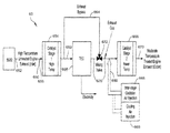
- FIG. 14 illustrates a block diagram of an underside of a vehicle 1400 that includes an exhaust and emissions system 1401 similar to the systems described above.
- the system 1401 is in fluid communication with a SI/IC engine 1420 that can operate at a stoichiometric or near stoichiometric AFR.
- the engine 1420 propels the vehicle 1400 via wheels 1410 and outputs an exhaust stream having an oxygen concentration by volume of close to zero, as discussed above.
- the exhaust stream is at a high temperature (e.g., about 800°-1250° F.).
- the exhaust stream is directed to a first-stage catalytic converter 1424 , which includes a reduction catalyst.
- the first-stage catalytic converter 1424 is a TWC.
- the first stage catalytic converter 1424 can remove (e.g., via reduction) NOx compounds from the exhaust stream.
- the output of the first stage catalytic converter 1424 is in fluid communication with an input of TEG 1426 .
- the TEG 1426 converts thermal energy in the exhaust stream to electricity, which can be used to charge a battery 1430 .
- the exhaust at the output of the TEG 1426 has a lower thermal energy (and thus a lower temperature) than the exhaust at the input of the TEG 1426 .
- the output of the TEG 1426 is in fluid communication via a conduit or pipe with an input of a second stage catalytic converter 1440 , which includes an oxidation catalyst.
- the second stage catalytic converter 1440 is a TWC.
- the second stage catalytic converter 1440 can remove (e.g., via oxidation) CO and, hydrogen gas, and/or organic compounds from the exhaust stream.
- An output of second stage catalytic converter 1440 is in fluid communication with an exhaust pipe 1450 . Additional components can be disposed between the second stage catalytic converter 1440 and the exhaust pipe 1450 such as a muffler.
- the exhaust Before the exhaust enters the second stage catalytic converter 1440 , the exhaust is optionally cooled by cooling unit 1446 and oxygenated by gas injector 1436 .
- the cooling unit 1446 removes thermal energy from the exhaust stream to decrease the temperature of the exhaust stream, for example to about 300-550° F., or any temperature or sub-range therebetween, as discussed above.
- the TEG 1426 cools the exhaust stream to about 300-550° F. without additional cooling from the cooling unit 1446 .
- the gas injector 1436 increases the oxygen content by volume of the exhaust stream to between about 0.25% and about 1.0%, or any value or sub-range therebetween.
- the exhaust and emissions system 1401 can include any of the variations and embodiments described above including a bypass conduit that bypasses the TEG 1426 .
- An embodiment is a vehicle having two catalysts and a TEG therebetween.
- the TEG can power an electrical component of the vehicle.
- the first catalyst removes (by reduction) NOx from the exhaust stream.
- the second catalyst removes (by oxidation) CO from the exhaust stream. Prior to entering the second catalyst, the exhaust stream is oxygenated and cooled.
Landscapes
- Engineering & Computer Science (AREA)
- Chemical & Material Sciences (AREA)
- Combustion & Propulsion (AREA)
- Chemical Kinetics & Catalysis (AREA)
- Mechanical Engineering (AREA)
- General Engineering & Computer Science (AREA)
- Health & Medical Sciences (AREA)
- Toxicology (AREA)
- Analytical Chemistry (AREA)
- Biomedical Technology (AREA)
- Environmental & Geological Engineering (AREA)
- General Chemical & Material Sciences (AREA)
- Oil, Petroleum & Natural Gas (AREA)
- Materials Engineering (AREA)
- Exhaust Gas After Treatment (AREA)
Abstract
Description
NOx yields N2+O2
CO+O2 yields CO2
Claims (24)
Priority Applications (1)
| Application Number | Priority Date | Filing Date | Title |
|---|---|---|---|
| US14/947,276 US9856767B2 (en) | 2010-04-28 | 2015-11-20 | Systems and methods for reducing emissions in exhaust of vehicles and producing electricity |
Applications Claiming Priority (4)
| Application Number | Priority Date | Filing Date | Title |
|---|---|---|---|
| US34339210P | 2010-04-28 | 2010-04-28 | |
| US12/816,706 US8578704B2 (en) | 2010-04-28 | 2010-06-16 | Assembly and method for reducing nitrogen oxides, carbon monoxide and hydrocarbons in exhausts of internal combustion engines |
| US13/616,752 US9631534B2 (en) | 2010-06-16 | 2012-09-14 | Assembly and method for reducing nitrogen oxides, carbon monoxide, hydrocarbons and hydrogen gas in exhausts of internal combustion engines and producing an electrical output |
| US14/947,276 US9856767B2 (en) | 2010-04-28 | 2015-11-20 | Systems and methods for reducing emissions in exhaust of vehicles and producing electricity |
Related Parent Applications (1)
| Application Number | Title | Priority Date | Filing Date |
|---|---|---|---|
| US13/616,752 Continuation-In-Part US9631534B2 (en) | 2010-04-28 | 2012-09-14 | Assembly and method for reducing nitrogen oxides, carbon monoxide, hydrocarbons and hydrogen gas in exhausts of internal combustion engines and producing an electrical output |
Publications (2)
| Publication Number | Publication Date |
|---|---|
| US20160076419A1 US20160076419A1 (en) | 2016-03-17 |
| US9856767B2 true US9856767B2 (en) | 2018-01-02 |
Family
ID=55454278
Family Applications (1)
| Application Number | Title | Priority Date | Filing Date |
|---|---|---|---|
| US14/947,276 Active 2030-11-16 US9856767B2 (en) | 2010-04-28 | 2015-11-20 | Systems and methods for reducing emissions in exhaust of vehicles and producing electricity |
Country Status (1)
| Country | Link |
|---|---|
| US (1) | US9856767B2 (en) |
Families Citing this family (11)
| Publication number | Priority date | Publication date | Assignee | Title |
|---|---|---|---|---|
| DE102012219968A1 (en) * | 2012-10-31 | 2014-06-12 | Bayerische Motoren Werke Aktiengesellschaft | Exhaust system with thermoelectric generator |
| EP3277410A4 (en) | 2015-03-24 | 2019-02-20 | Tecogen, Inc. | CATALYST RESISTANT TO POISONS, AND SYSTEMS CONTAINING THE SAME |
| JP2019513930A (en) * | 2016-04-04 | 2019-05-30 | テコジェン インク.Techogen Inc. | Emission control system and method for a motor vehicle |
| US10774720B2 (en) | 2017-02-11 | 2020-09-15 | Tecogen, Inc. | NOx reduction without urea using a dual stage catalyst system with intercooling in vehicle gasoline engines |
| WO2018147912A1 (en) * | 2017-02-11 | 2018-08-16 | Tecogen, Inc. | Nox reduction without urea using a dual stage catalyst system with intercooling in vehicle gasoline engines |
| JP2020509284A (en) * | 2017-02-11 | 2020-03-26 | テコジェン インク.Techogen Inc. | Two-stage internal combustion engine aftertreatment system using exhaust gas intercooling and a charger driven air blast device |
| US10337374B2 (en) * | 2017-03-15 | 2019-07-02 | Ford Global Technologies, Llc | Methods and systems for an aftertreatment catalyst |
| US11268415B2 (en) * | 2017-06-02 | 2022-03-08 | Volvo Truck Corporation | Method for controlling the temperature of a NOx controlling component and an exhaust after treatment system |
| PL234328B1 (en) * | 2017-06-26 | 2020-02-28 | Inst Techniki Gorniczej Komag | Device for cooling exhaust gases from compression-ignition combustion engines |
| CN110206620B (en) * | 2019-05-06 | 2021-01-15 | 江苏大学 | Self-feedback adjusting baffle type SCR urea mixer |
| CN115853617B (en) * | 2022-12-28 | 2024-08-20 | 东风商用车有限公司 | Hydrogen engine tail gas treatment device and method |
Citations (4)
| Publication number | Priority date | Publication date | Assignee | Title |
|---|---|---|---|---|
| US5603215A (en) * | 1995-03-23 | 1997-02-18 | Engelhard Corporation | Method and apparatus for treatment of exhaust streams |
| US20040206069A1 (en) * | 2003-04-16 | 2004-10-21 | Prasad Tumati | Thermal management of exhaust systems |
| US20110240080A1 (en) * | 2010-04-02 | 2011-10-06 | Gm Global Technology Operation, Inc. | Method of controlling temperature of a thermoelectric generator in an exhaust system |
| US20110311421A1 (en) * | 2010-06-21 | 2011-12-22 | Monika Backhaus-Ricoult | Exhaust gas treatment system including a thermoelectric generator |
-
2015
- 2015-11-20 US US14/947,276 patent/US9856767B2/en active Active
Patent Citations (4)
| Publication number | Priority date | Publication date | Assignee | Title |
|---|---|---|---|---|
| US5603215A (en) * | 1995-03-23 | 1997-02-18 | Engelhard Corporation | Method and apparatus for treatment of exhaust streams |
| US20040206069A1 (en) * | 2003-04-16 | 2004-10-21 | Prasad Tumati | Thermal management of exhaust systems |
| US20110240080A1 (en) * | 2010-04-02 | 2011-10-06 | Gm Global Technology Operation, Inc. | Method of controlling temperature of a thermoelectric generator in an exhaust system |
| US20110311421A1 (en) * | 2010-06-21 | 2011-12-22 | Monika Backhaus-Ricoult | Exhaust gas treatment system including a thermoelectric generator |
Also Published As
| Publication number | Publication date |
|---|---|
| US20160076419A1 (en) | 2016-03-17 |
Similar Documents
| Publication | Publication Date | Title |
|---|---|---|
| US9856767B2 (en) | Systems and methods for reducing emissions in exhaust of vehicles and producing electricity | |
| US9121326B2 (en) | Assembly and method for reducing nitrogen oxides, carbon monoxide and hydrocarbons in exhausts of internal combustion engines | |
| US7811527B2 (en) | Exhaust purification with on-board ammonia production | |
| US8056320B2 (en) | Cold-start control systems for internal combustion engines | |
| US20080223019A1 (en) | Scr cold start heating system for a diesel exhaust | |
| CN101874150A (en) | Exhaust gas purification system and exhaust gas purification method | |
| US9631534B2 (en) | Assembly and method for reducing nitrogen oxides, carbon monoxide, hydrocarbons and hydrogen gas in exhausts of internal combustion engines and producing an electrical output | |
| JP4566193B2 (en) | Method for reducing NOx in exhaust gas of a heat engine with a catalyst and apparatus for carrying out the method | |
| US10934912B2 (en) | Method for the exhaust aftertreatment of an internal combustion engine and exhaust aftertreatment system | |
| US20080022666A1 (en) | Balanced partial two-stroke engine | |
| US20200023314A1 (en) | A novel exhaust after-treatment system for a diesel engine or a spark ignition gasoline, cng,lng, engine | |
| US9470126B2 (en) | Assembly and method for reducing ammonia in exhaust of internal combustion engines | |
| JP3577946B2 (en) | Compression ignition type internal combustion engine having a combustion type heater | |
| US20140086803A1 (en) | Nox reduction | |
| EP2821606B1 (en) | Method for reducing nitrogen oxides, carbon monoxide and hydrocarbons in exhausts of internal combustion engines | |
| WO2011136756A1 (en) | Assembly and method for reducing nitrogen oxides, carbon monoxide and hydrocarbons in exhausts of internal combustion engines | |
| EP1974132B1 (en) | System for introducing gas into a motor vehicle engine exhaust line | |
| US7849681B2 (en) | Apparatus, system, and method for engine-generated heat utilization in a NOx-adsorber aftertreatment system | |
| GB2547205A (en) | An exhaust system | |
| JPH1026014A (en) | Exhaust gas purification device for internal combustion engine |
Legal Events
| Date | Code | Title | Description |
|---|---|---|---|
| AS | Assignment |
Owner name: TECOGEN INC., MASSACHUSETTS Free format text: ASSIGNMENT OF ASSIGNORS INTEREST;ASSIGNOR:ROY, JEAN;REEL/FRAME:039116/0205 Effective date: 20160614 |
|
| STCF | Information on status: patent grant |
Free format text: PATENTED CASE |
|
| AS | Assignment |
Owner name: WEBSTER BUSINESS CREDIT CORPORATION, NEW YORK Free format text: SECURITY INTEREST;ASSIGNOR:TECOGEN INC.;REEL/FRAME:046083/0223 Effective date: 20180504 |
|
| MAFP | Maintenance fee payment |
Free format text: PAYMENT OF MAINTENANCE FEE, 4TH YR, SMALL ENTITY (ORIGINAL EVENT CODE: M2551); ENTITY STATUS OF PATENT OWNER: SMALL ENTITY Year of fee payment: 4 |
|
| AS | Assignment |
Owner name: TECOGEN, INC., MASSACHUSETTS Free format text: RELEASE BY SECURED PARTY;ASSIGNOR:WEBSTER BUSINESS CREDIT CORPORATION;REEL/FRAME:056272/0587 Effective date: 20210512 |
|
| FEPP | Fee payment procedure |
Free format text: MAINTENANCE FEE REMINDER MAILED (ORIGINAL EVENT CODE: REM.); ENTITY STATUS OF PATENT OWNER: SMALL ENTITY |
|
| FEPP | Fee payment procedure |
Free format text: 7.5 YR SURCHARGE - LATE PMT W/IN 6 MO, SMALL ENTITY (ORIGINAL EVENT CODE: M2555); ENTITY STATUS OF PATENT OWNER: SMALL ENTITY |
|
| MAFP | Maintenance fee payment |
Free format text: PAYMENT OF MAINTENANCE FEE, 8TH YR, SMALL ENTITY (ORIGINAL EVENT CODE: M2552); ENTITY STATUS OF PATENT OWNER: SMALL ENTITY Year of fee payment: 8 |