US9855104B2 - Locking screw length measurement - Google Patents
Locking screw length measurement Download PDFInfo
- Publication number
- US9855104B2 US9855104B2 US14/401,715 US201214401715A US9855104B2 US 9855104 B2 US9855104 B2 US 9855104B2 US 201214401715 A US201214401715 A US 201214401715A US 9855104 B2 US9855104 B2 US 9855104B2
- Authority
- US
- United States
- Prior art keywords
- bone
- ray image
- imaged
- model
- screw
- Prior art date
- Legal status (The legal status is an assumption and is not a legal conclusion. Google has not performed a legal analysis and makes no representation as to the accuracy of the status listed.)
- Active, expires
Links
Images


Classifications
-
- A—HUMAN NECESSITIES
- A61—MEDICAL OR VETERINARY SCIENCE; HYGIENE
- A61B—DIAGNOSIS; SURGERY; IDENTIFICATION
- A61B34/00—Computer-aided surgery; Manipulators or robots specially adapted for use in surgery
- A61B34/10—Computer-aided planning, simulation or modelling of surgical operations
-
- A—HUMAN NECESSITIES
- A61—MEDICAL OR VETERINARY SCIENCE; HYGIENE
- A61B—DIAGNOSIS; SURGERY; IDENTIFICATION
- A61B6/00—Apparatus or devices for radiation diagnosis; Apparatus or devices for radiation diagnosis combined with radiation therapy equipment
- A61B6/12—Arrangements for detecting or locating foreign bodies
-
- A—HUMAN NECESSITIES
- A61—MEDICAL OR VETERINARY SCIENCE; HYGIENE
- A61B—DIAGNOSIS; SURGERY; IDENTIFICATION
- A61B6/00—Apparatus or devices for radiation diagnosis; Apparatus or devices for radiation diagnosis combined with radiation therapy equipment
- A61B6/50—Apparatus or devices for radiation diagnosis; Apparatus or devices for radiation diagnosis combined with radiation therapy equipment specially adapted for specific body parts; specially adapted for specific clinical applications
- A61B6/505—Apparatus or devices for radiation diagnosis; Apparatus or devices for radiation diagnosis combined with radiation therapy equipment specially adapted for specific body parts; specially adapted for specific clinical applications for diagnosis of bone
-
- A—HUMAN NECESSITIES
- A61—MEDICAL OR VETERINARY SCIENCE; HYGIENE
- A61B—DIAGNOSIS; SURGERY; IDENTIFICATION
- A61B17/00—Surgical instruments, devices or methods
- A61B17/16—Instruments for performing osteoclasis; Drills or chisels for bones; Trepans
- A61B17/17—Guides or aligning means for drills, mills, pins or wires
- A61B17/1725—Guides or aligning means for drills, mills, pins or wires for applying transverse screws or pins through intramedullary nails or pins
-
- A—HUMAN NECESSITIES
- A61—MEDICAL OR VETERINARY SCIENCE; HYGIENE
- A61B—DIAGNOSIS; SURGERY; IDENTIFICATION
- A61B17/00—Surgical instruments, devices or methods
- A61B17/56—Surgical instruments or methods for treatment of bones or joints; Devices specially adapted therefor
- A61B17/58—Surgical instruments or methods for treatment of bones or joints; Devices specially adapted therefor for osteosynthesis, e.g. bone plates, screws or setting implements
- A61B17/68—Internal fixation devices, including fasteners and spinal fixators, even if a part thereof projects from the skin
- A61B17/72—Intramedullary devices, e.g. pins or nails
-
- A—HUMAN NECESSITIES
- A61—MEDICAL OR VETERINARY SCIENCE; HYGIENE
- A61B—DIAGNOSIS; SURGERY; IDENTIFICATION
- A61B17/00—Surgical instruments, devices or methods
- A61B17/56—Surgical instruments or methods for treatment of bones or joints; Devices specially adapted therefor
- A61B17/58—Surgical instruments or methods for treatment of bones or joints; Devices specially adapted therefor for osteosynthesis, e.g. bone plates, screws or setting implements
- A61B17/68—Internal fixation devices, including fasteners and spinal fixators, even if a part thereof projects from the skin
- A61B17/84—Fasteners therefor or fasteners being internal fixation devices
- A61B17/86—Pins or screws or threaded wires; nuts therefor
-
- A—HUMAN NECESSITIES
- A61—MEDICAL OR VETERINARY SCIENCE; HYGIENE
- A61B—DIAGNOSIS; SURGERY; IDENTIFICATION
- A61B34/00—Computer-aided surgery; Manipulators or robots specially adapted for use in surgery
- A61B34/10—Computer-aided planning, simulation or modelling of surgical operations
- A61B2034/101—Computer-aided simulation of surgical operations
- A61B2034/105—Modelling of the patient, e.g. for ligaments or bones
-
- A—HUMAN NECESSITIES
- A61—MEDICAL OR VETERINARY SCIENCE; HYGIENE
- A61B—DIAGNOSIS; SURGERY; IDENTIFICATION
- A61B34/00—Computer-aided surgery; Manipulators or robots specially adapted for use in surgery
- A61B34/10—Computer-aided planning, simulation or modelling of surgical operations
- A61B2034/108—Computer aided selection or customisation of medical implants or cutting guides
-
- A—HUMAN NECESSITIES
- A61—MEDICAL OR VETERINARY SCIENCE; HYGIENE
- A61B—DIAGNOSIS; SURGERY; IDENTIFICATION
- A61B90/00—Instruments, implements or accessories specially adapted for surgery or diagnosis and not covered by any of the groups A61B1/00 - A61B50/00, e.g. for luxation treatment or for protecting wound edges
- A61B90/06—Measuring instruments not otherwise provided for
- A61B2090/061—Measuring instruments not otherwise provided for for measuring dimensions, e.g. length
Definitions
- the invention relates to the field of computer assisted surgery. Particularly, the invention relates to a computer software based method for identifying a length of a bone screw to be inserted through a bore in a bone. Furthermore, the invention relates to a corresponding device and to a method of operating the same.
- a bone screw and in particular a locking screw for fixating a bone nail is inserted into a bone by opening the tissue surrounding the bone, to achieve an access to the bone at a site at which it is intended to introduce a screw.
- a bore is drilled into the bone forming a channel for the screw. Into such a channel, a bone screw may be screwed in.
- a critical aspect of such an insertion of a bone screw is that the screw should have a length which is long enough to provide sufficient stability, i.e. as much as possible of the thread of the screw should engage with hard bone tissue (Corticalis), but the screw should, on the other hand, have a length which is not too long so that at least one end section of the screw may protrude out of the bone which may cause irritations and insurances at the surrounding soft tissue, i.e. muscles or sinews.
- a physician will usually have access to a bone only from one side, i.e. at the entry point for the screw, it is difficult to measure the length or depth of a bore into which a screw should be introduced.
- a method comprises, in general, the steps of identifying a predetermined or intended drilling direction and a predetermined or intended position in a first X-ray projection image of the bone, transferring the identified direction and position to a corresponding 3D bone model, and determining the length of the bone screw at the bone model, based on the transferred direction and position.
- the term “bone model” encompasses, for example, a 3D model of a bone.
- the bone model may be generated based on at least one 3D scan of at least one real bone of the same kind, for example a femur or humerus, and/or by forming an average from a plurality of 3D scans.
- An exemplary utilization of bone models is described in ‘Evidence based development of a novel lateral fibula plate (VariAX Fibula) using a real CT bone data based optimization process during device development’ of A. P. Schulz et al. (The Open Orthopaedics Journal, 2012, 6, 1-7), the content of which is incorporated herein by reference.
- a length between two points wherein at least one of these points is obscured i.e. not visible in the projection image.
- a depth of a structure may be determined in a projection image of the structure.
- the identification of the predetermined position at the bone includes a measurement of the distances between the bore and the outer surface of the imaged bone (i) in an axial direction of the bone and (ii) in a direction perpendicular to the axial direction of the bone.
- the position of the center point of the bore axis, when looking in the direction of the bore axis, is measured in a longitudinal direction and a transverse direction of the bone. It will be understood that the direction of the bore axis is identical to the drilling direction.
- the method further comprises the step of determining a diameter of the imaged bone between two opposed outer surfaces of the imaged bone in relation to a reference body which is also visible in the X-ray image.
- the diameter may be the distance between both outer bone surfaces in a transverse direction of the bone, preferably in the same transverse direction as the transverse direction in which the position of the bore is identified or measured.
- the dimensions of the reference body will be known so that a factor can be calculated representing the relation between, for example, a length of the reference body as imaged and an actual length of the reference body. This factor may subsequently be used to determine for example an actual diameter of an imaged bone.
- the actual diameter of the imaged bone may in turn lead to a bone model, wherein at least the size of the bone model fits to the imaged bone so that a length which is not visible in the image can be determined at the bone model.
- a particular bone like a femur has an almost constant relation between its length and its width, i.e. the femur has a specific shape regardless of its size. Therefore, a bone model can be selected based on only one measured dimension, for example a diameter of the shaft in one direction. It can be assumed as very likely that other dimensions of the bone model like the length or a diameter perpendicular to the measure diameter correlate to the corresponding actual dimensions of an imaged bone.
- the data of the first X-ray image may be received directly from an imaging device, for example from a 2D C-arm based X-ray device.
- the image may represent an anatomical structure of interest, in particular a bone.
- the method further comprises the step of selecting a bone model from a group of bone models with different sizes and shapes, the selected bone model corresponding to the imaged bone.
- the group of bone models may be stored in a database. Further, the group of bone models may be a selection of previously generated 3D images, each of another person, wherein the persons may differ in size, weight and age.
- the database may thus contain several models of each bone (e.g. tibia, femur, humerus) including bone models of different ages, genders and individual sizes.
- the software uses gray scale image data to determine at least one dimension from the x-ray (2D image) of the bone to be treated and searches the database for a bone model of a person of the same age, gender and size, for example, having an identical or at least a close approximation to the at least one dimension from the bone to be treated.
- a three dimensional model of the matched bone in the database is selected and utilized as a corresponding 3D bone model of the bone to be treated.
- the method further comprises the step of adapting a bone model so that the bone model corresponds to the imaged bone.
- the bone model may be stored in a database.
- the bone model may be generated by forming an average of a plurality of previously generated 3D images.
- substantially the size of the bone model may be increased or decreased so as to fit to the size of the bone as measured in the image.
- the first X-ray image is generated in a direction being parallel to the drilling direction.
- the first X-ray image is generated from a point of view from which one may look in a direction in which the axis of the bore extends, i.e. one may look for example perpendicular onto the bone. From such a point of view it may be easier to identify outer surfaces of the bone and to measure a distance from a distinct outer surface to the center of the bore.
- the length of the bone screw may correspond to the distance between the outer surfaces of the bone at both ends of the bore with the bore being a through bore through a long bone.
- the method may further comprises the step of determining a diameter of the imaged bone between two opposed outer surfaces of the imaged bone in relation to the reference body which is also visible in a second X-ray image of the bone, wherein the imaging directions of the first X-ray image and the second X-ray image differ from each other.
- a second X-ray image may serve as a means to control the expected dimensions of an imaged bone to ensure that the used bone model fits both in size and shape to the imaged bone.
- the method does not include any step leading to a situation in which a bone nail is positioned in a bone, in so far as the step constitutes a treatment of a human or animal body by surgery.
- a device for identifying a length of a bone screw to be inserted through a bore drilled in a predetermined drilling direction at a predetermined position through a bone comprises a processing unit adapted for executing the above described method, i.e. comprises a processing unit adapted for identifying the predetermined direction and the predetermined position at the bone in an X-ray image, transferring the identified direction and position to a corresponding bone model, and determining the length of the bone screw based on the transferred direction and position at the bone model.
- the device comprises storage means providing a database. It will be understood, that such storage means may also be provided in a network to which the system may be connected and information related to the bone model, i.e. different types of models and parameter thereof, may be received over that network.
- the device may comprise an imaging unit for generating the at least one X-ray image, wherein the imaging unit may be capable of generating images from different directions.
- the device may further comprise input means for manually determining a position in the X-ray image, for example a bone surface, for measuring a distance in the image.
- input means may be for example a computer keyboard, a computer mouse or a touch screen, to control a pointing device like a cursor on a monitor screen which may also be included in the device.
- the processing unit is further adapted for adapting the bone model so that the bone model corresponds to the imaged bone.
- processing means may be realized by only one processor performing all the described steps, or by a group or plurality of processors, for example a system processor for processing the image data including an identification of anatomical structures like a bone surface, a separate processor specialized on processing of a bone model and determining distances, and a further processor for controlling a monitor for visualizing the result.
- a system processor for processing the image data including an identification of anatomical structures like a bone surface
- a separate processor specialized on processing of a bone model and determining distances
- a further processor for controlling a monitor for visualizing the result.
- a computer software which when executed on a device as described, causes the device to perform the steps of the method as described.
- the computer software may include sets of instructions for determining a position on a bone surface and/or a diameter between outer surfaces so that such determination may be performed automatically. It will be understood that the computer program may further include sets of instructions to identify a reference object in the image.
- a corresponding computer program may preferably be loaded into a work memory of a data processor.
- the data processor or processing unit may thus be equipped to carry out at least a part of the described method.
- the invention relates to a computer-readable medium such as a CD-ROM at which the computer program may be stored.
- the computer program may also be presented over a network like the World Wide Web and can be downloaded into the working memory of the data processor from such a network.
- FIG. 1 shows a flow chart of steps performed in accordance with a method described herein.
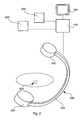
- FIG. 2 shows a schematical illustration of a system according to an embodiment described herein.
- FIG. 3 illustrates a transfer of a distance in a longitudinal direction from an imaged bone to a bone model.
- FIG. 4 illustrates a transfer of a distance in a transverse direction from an imaged bone to a bone model.
- FIG. 5 shows a bone together with a screw imaged from a second direction.
- FIG. 1 illustrates the principle of the steps performed in accordance with the described method. It will be understood that the steps described, are major steps, wherein these major steps might be differentiated or divided into several sub-steps. Furthermore, there might be also sub-steps between these major steps.
- a first X-ray image is received, wherein this X-ray image may be generated for example in a medial-lateral direction.
- the first X-ray image shows a region of interest including a position at a bone into which a screw is to be inserted.
- the X-ray image further shows a reference body.
- step S 12 a scale factor is determined based on the actual and the imaged dimensions of the reference body.
- step S 13 a first dimension of the bone is measured in the X-ray image and the corresponding first dimension of the actual bone is determined.
- step S 14 a 3D bone model is selected or adapted, at least the first dimension of which fits to the first dimension of the actual bone.
- step S 15 the location on the bone surface at which a bone screw should be inserted as well as a drilling direction is identified.
- the drilling direction may be easy identified in a case in which a tissue protection sleeve is visible in the X-ray image.
- a bore will be provided in the drilling direction into which a bone screw may subsequently be screwed in.
- step S 16 the identified point and direction is transferred to the selected and/or adapted bone model.
- step S 17 a distance is measured at the 3D bone model, the distance representing an appropriate length for a screw which thus can be accurately inserted into the bone at the identified position and in the identified direction.
- a second X-ray image may be received in step S 21 .
- the second X-ray image should be generated from an imaging direction which is different to the imaging direction of the first X-ray image.
- the second X-ray image may be generated in an anterior-posterior direction.
- the first X-ray image shows the region of interest as well as a reference body.
- a further scale factor is determined based on the actual and the imaged dimensions of the reference body. It is noted that the further scale factor may be utilized for all dimensions related to the projection plane of the second X-ray image. In this case, the scale factor as determined in step S 12 may thus only be utilized for the dimensions related to the projection plane of the first X-ray image.
- step S 23 a second dimension of the bone is measured in the second X-ray image and the corresponding second dimension of the actual bone is determined.
- step S 23 a 3D bone model is selected or adapted in step S 14 , wherein in this case the first and second dimensions as well as both scale factors are taken into account. Subsequently, steps S 15 to S 17 are performed as described above.
- a physician may be provided with information supporting the decision which bone screw should be used.
- FIG. 2 shows an embodiment of a device. Substantially necessary for performing the described steps, the device comprises a processing unit 100 and a monitor 400 .
- the exemplary imaging device 200 includes an X-ray source 240 , and an X-ray detector 260 , wherein these two devices are mounted on a C-arm 220 . It will be understood that the device may also comprise another non-invasive imaging modality like a computer tomography device as imaging device instead of or additional to the shown C-arm based X-ray device, to generated individual projection images.
- the device in FIG. 2 includes an input device 300 , by means of which for example a manual determination of a position on a bone surface may be performed. Also shown is a connection (as dotted line) to a database 600 , located for example in a network.
- a region of interest 500 there is shown a region of interest 500 .
- a bone of a patient may be located, wherein it is intended to introduce a screw into that bone, but an appropriate length of the screw has to be identified.
- FIGS. 3 to 5 illustrate an embodiment of a method, wherein the method is performed to determine a length of a screw which should be inserted through a lateral bore of a bone nail at a distal end of a femur.
- FIG. 3 shows a schematically visualization of an X-ray image (encircled) together with a bone model.
- the X-ray image is a 2D projection image of a distal end portion of a femur 10 , generated in a medial-lateral direction.
- a bone nail 20 is located within the medullary channel of the femur 10 .
- the tip 22 of the bone nail 20 is located in the femur with a distance D away from the most distal point of the femur 10 .
- a center of a bore 24 through the bone nail 20 is provided. In this example, it is assumed that a locking screw should be inserted through bore 24 .
- the bone nail 20 may serve as a reference body.
- the actual amount of the distance X is known so that a scale factor can be calculated based on the actual distance X and on the distance X as measured in the X-ray image. Accordingly, the actual distance which corresponds to the distance D as imaged may be determined utilizing the scale factor.
- the diameter of the femur is measured in the X-ray image so as to determine the actual diameter of the femur shaft at a distinct distance from the most distal point of the femur. Based on the determined actual diameter, a corresponding bone model 50 can be selected and, if necessary, adapted to the determined actual diameter of the femur.
- a plane or slice may be identified through which a screw should be inserted.
- This plane or slice 56 may be identified in a distance D+X measured from the most distal point at the bone model of the femur, with the known distance X and the determined distance D.
- a plan view of the identified slice 56 is shown in FIG. 4 .
- FIG. 4 the 2D projection image of FIG. 3 is shown again, but with an indication of the longitudinal axis 26 of the bone nail 20 and the center line 16 of the shaft of the femur 10 .
- the bone nail is located within the upper half of the femur.
- the slice 56 is shown in FIG. 4 with the center line of the slice being identical to the center line in the X-ray projection image next to it, and with the axis of the bone nail being identical to the axis 26 of the bone nail 20 in said X-ray projection image.
- a height H can be determined at which the screw is to be inserted through the femur, thus extending through the transverse bore of the bone nail. It is noted that the height, i.e. the position of the bore measured in an anterior-posterior direction, may also be determined relative to one of the outer surfaces of the femur instead of the center line thereof.
- the outer contour of the bone is not regular.
- the distance between two opposite outer surfaces vary depending on the position and/or angle at which the distance is measured.
- the horizontal width L in the height H differs from the width L max which would be recognizable in an X-ray image generated in a vertical direction, i.e. perpendicular to the width.
- the width L is smaller than the width L max .
- FIG. 5 only a schematically X-ray projection image is shown, wherein this X-ray image is generated in an anterior-posterior direction, i.e. from above when the person is lying on his/her back.
- FIG. 5 shows the femur 10 , the bone nail 20 as well as an aiming device 60 , wherein a tissue protection sleeve 70 is arranged at the aiming device.
- the tissue protection sleeve 70 may serve firstly as a reference body for the determination of a further scale factor, secondly as a guide element for guiding a drill which is used to drill a channel for a screw through the bone, and thirdly as a means for allowing the screw to be accurately inserted into the drilled bore without interfering with surrounding tissue.
- the bone nail 20 and alternatively the arm of the aiming device 60 may serve as a reference body for determining the further scale factor.
- the length of the screw is smaller than the overall width of the bone as visualized in the X-ray projection image.
- the length of the screw is appropriate for an introduction at the intended position (distance to distal end of bone and height relative to bone axis) and in the intended direction.
- the computer program may be stored/distributed on a suitable medium such as an optical storage medium or a solid-state medium supplied together with or as a part of another hardware, but may also be distributed in other forms, such as via the Internet or other wired or wireless telecommunication systems. Any reference signs in the claims should not be construed as limiting the scope.
Landscapes
- Health & Medical Sciences (AREA)
- Life Sciences & Earth Sciences (AREA)
- Engineering & Computer Science (AREA)
- Medical Informatics (AREA)
- Surgery (AREA)
- Heart & Thoracic Surgery (AREA)
- Molecular Biology (AREA)
- Nuclear Medicine, Radiotherapy & Molecular Imaging (AREA)
- Veterinary Medicine (AREA)
- Public Health (AREA)
- General Health & Medical Sciences (AREA)
- Biomedical Technology (AREA)
- Animal Behavior & Ethology (AREA)
- Radiology & Medical Imaging (AREA)
- Biophysics (AREA)
- Physics & Mathematics (AREA)
- High Energy & Nuclear Physics (AREA)
- Pathology (AREA)
- Optics & Photonics (AREA)
- Robotics (AREA)
- Orthopedic Medicine & Surgery (AREA)
- Dentistry (AREA)
- Oral & Maxillofacial Surgery (AREA)
- Apparatus For Radiation Diagnosis (AREA)
- Surgical Instruments (AREA)
Abstract
Description
- 10 femur
- 16 center line of femur shaft
- 20 bone nail
- 22 tip of bone nail
- 24 transverse bore
- 26 axis of bone nail
- 30 screw
- 50 bone model
- 52 medullary channel of bone model
- 54 Corticalis of bone model
- 56 slice of bone model
- 60 aiming device
- 70 tissue protection sleeve
- 100 processing means
- 200 imaging device
- 220 C-arm
- 240 X-ray source
- 260 X-ray detector
- 300 input device
- 400 monitor
- 500 region of interest
- 600 database
Claims (13)
Applications Claiming Priority (1)
| Application Number | Priority Date | Filing Date | Title |
|---|---|---|---|
| PCT/EP2012/002207 WO2013174402A1 (en) | 2012-05-23 | 2012-05-23 | Locking screw length measurement |
Publications (2)
| Publication Number | Publication Date |
|---|---|
| US20150164445A1 US20150164445A1 (en) | 2015-06-18 |
| US9855104B2 true US9855104B2 (en) | 2018-01-02 |
Family
ID=46148822
Family Applications (1)
| Application Number | Title | Priority Date | Filing Date |
|---|---|---|---|
| US14/401,715 Active 2033-10-23 US9855104B2 (en) | 2012-05-23 | 2012-05-23 | Locking screw length measurement |
Country Status (4)
| Country | Link |
|---|---|
| US (1) | US9855104B2 (en) |
| EP (1) | EP2852347B1 (en) |
| ES (1) | ES2684140T3 (en) |
| WO (1) | WO2013174402A1 (en) |
Cited By (1)
| Publication number | Priority date | Publication date | Assignee | Title |
|---|---|---|---|---|
| EP3692939A1 (en) | 2019-02-07 | 2020-08-12 | Stryker European Operations Limited | Surgical systems for facilitating tissue treatment |
Families Citing this family (11)
| Publication number | Priority date | Publication date | Assignee | Title |
|---|---|---|---|---|
| EP2852347B1 (en) * | 2012-05-23 | 2018-06-20 | Stryker European Holdings I, LLC | Locking screw length measurement |
| EP2852337B1 (en) | 2012-05-23 | 2019-08-14 | Stryker European Holdings I, LLC | Entry portal navigation |
| US11229490B2 (en) | 2013-06-26 | 2022-01-25 | Corindus, Inc. | System and method for monitoring of guide catheter seating |
| US20150005745A1 (en) * | 2013-06-26 | 2015-01-01 | Corindus, Inc. | 3-d mapping for guidance of device advancement out of a guide catheter |
| CN104622559B (en) * | 2014-12-23 | 2017-03-15 | 河海大学常州校区 | A kind of construction method of parametrization femur template |
| ES2984739T3 (en) * | 2016-07-18 | 2024-10-30 | Stryker European Operations Holdings Llc | Surgical site displacement tracking system |
| EP3541270A4 (en) | 2016-11-18 | 2020-06-10 | Stryker Corp. | METHOD AND APPARATUS FOR TREATMENT OF A JOINT, INCLUDING THE TREATMENT OF A FEMORO-ACETABULAR CONFLICT IN A HIP JOINT AND A FEMORO-ACETABULAR CONFLICT OF A CLIP TYPE IN A HIP JOINT |
| US11464569B2 (en) | 2018-01-29 | 2022-10-11 | Stryker Corporation | Systems and methods for pre-operative visualization of a joint |
| US12502218B2 (en) | 2019-02-08 | 2025-12-23 | Stryker Corporation | Systems and methods for treating a joint |
| CN115942913B (en) | 2020-02-21 | 2026-01-06 | 史赛克公司 | Systems and methods for visually guided bone removal during joint surgical procedures |
| WO2022133442A1 (en) | 2020-12-15 | 2022-06-23 | Stryker Corporation | Systems and methods for generating a three-dimensional model of a joint from two-dimensional images |
Citations (36)
| Publication number | Priority date | Publication date | Assignee | Title |
|---|---|---|---|---|
| US4106128A (en) | 1976-12-06 | 1978-08-15 | Greenwald A Seth | Endoprosthetic bone joint |
| US5398684A (en) | 1988-12-23 | 1995-03-21 | Hardy; Tyrone L. | Method and apparatus for video presentation from scanner imaging sources |
| US5799055A (en) | 1996-05-15 | 1998-08-25 | Northwestern University | Apparatus and method for planning a stereotactic surgical procedure using coordinated fluoroscopy |
| US6064932A (en) | 1995-07-25 | 2000-05-16 | Cesa-Campagnie Eurpeene De Sieges Pour Automobiles | Assembly for adjusting the position of at least two motor vehicle components |
| US6470207B1 (en) | 1999-03-23 | 2002-10-22 | Surgical Navigation Technologies, Inc. | Navigational guidance via computer-assisted fluoroscopic imaging |
| US6682565B1 (en) | 1999-09-14 | 2004-01-27 | Flinders University | Joint prosthesis |
| US6701174B1 (en) | 2000-04-07 | 2004-03-02 | Carnegie Mellon University | Computer-aided bone distraction |
| US6711432B1 (en) | 2000-10-23 | 2004-03-23 | Carnegie Mellon University | Computer-aided orthopedic surgery |
| US20040068187A1 (en) | 2000-04-07 | 2004-04-08 | Krause Norman M. | Computer-aided orthopedic surgery |
| US20040111024A1 (en) * | 2001-02-07 | 2004-06-10 | Guoyan Zheng | Method for establishing a three-dimensional representation of a bone from image data |
| WO2004069040A2 (en) | 2003-02-04 | 2004-08-19 | Z-Kat, Inc. | Method and apparatus for computer assistance with intramedullary nail procedure |
| US20040240715A1 (en) | 2003-05-29 | 2004-12-02 | Wicker Ryan B. | Methods and systems for image-guided placement of implants |
| US20050251113A1 (en) * | 2000-11-17 | 2005-11-10 | Kienzle Thomas C Iii | Computer assisted intramedullary rod surgery system with enhanced features |
| US20060015188A1 (en) | 2004-07-17 | 2006-01-19 | Nexus Consulting Limited | Prosthesis and method of implantation |
| US20070270680A1 (en) | 2006-03-22 | 2007-11-22 | Garrett Sheffer | Modeling method and apparatus for use in surgical navigation |
| US20080075348A1 (en) * | 2006-09-21 | 2008-03-27 | Dan Rappaport | Medical image analysis |
| US20080175464A1 (en) | 2007-01-16 | 2008-07-24 | Optasia Medical, Ltd. | Computer program products and methods for detection and tracking of rheumatoid arthritis |
| US20080294265A1 (en) | 2007-05-22 | 2008-11-27 | Blaine Warkentine | Navigated placement of pelvic implant based on combined anteversion by applying ranawat's sign or via arithmetic formula |
| US20080319448A1 (en) | 2006-12-12 | 2008-12-25 | Perception Raisonnement Action En Medecine | System and method for determining an optimal type and position of an implant |
| US20090017430A1 (en) * | 2007-05-15 | 2009-01-15 | Stryker Trauma Gmbh | Virtual surgical training tool |
| US20090209851A1 (en) * | 2008-01-09 | 2009-08-20 | Stryker Leibinger Gmbh & Co. Kg | Stereotactic computer assisted surgery method and system |
| US20100241129A1 (en) | 2009-03-18 | 2010-09-23 | Integrated Spinal Concepts, Inc. | Image-Guided Minimal-Step Placement Of Screw Into Bone |
| WO2010121147A1 (en) | 2009-04-16 | 2010-10-21 | Conformis, Inc. | Patient-specific joint arthroplasty devices for ligament repair |
| WO2010122145A1 (en) | 2009-04-25 | 2010-10-28 | Siemens Aktiengesellschaft | A method and a system for assessing the relative pose of an implant and a bone of a creature |
| US20110082367A1 (en) * | 2009-08-07 | 2011-04-07 | Luca Regazzoni | Method and apparatus for reducing malalignment of fractured bone fragments |
| US20110092804A1 (en) | 2006-02-27 | 2011-04-21 | Biomet Manufacturing Corp. | Patient-Specific Pre-Operative Planning |
| US20110213379A1 (en) * | 2010-03-01 | 2011-09-01 | Stryker Trauma Gmbh | Computer assisted surgery system |
| EP2363083A1 (en) | 2010-03-01 | 2011-09-07 | Stryker Trauma GmbH | Computer assisted surgery system |
| US20130211386A1 (en) * | 2010-07-16 | 2013-08-15 | Stryker Trauma Gmbh | Surgical targeting system and method |
| US20130317512A1 (en) * | 2010-12-23 | 2013-11-28 | Stryker Trauma Gmbh | Devices and methods for monitoring the rotational orientation of bone fragments |
| US20150164445A1 (en) * | 2012-05-23 | 2015-06-18 | Stryker European Holdings I, Llc | Locking screw length measurement |
| US9119722B1 (en) | 2011-08-18 | 2015-09-01 | Sharat Kusuma | Measurement and placement techniques in hip resurfacing and the like |
| US20150265361A1 (en) * | 2012-09-27 | 2015-09-24 | Stryker European Holdings I, Llc | Rotational position determination |
| US20160278824A1 (en) * | 2015-03-25 | 2016-09-29 | Medartis Holding Ag | Method for treating fractures of a bone |
| US20160296285A1 (en) * | 2013-10-10 | 2016-10-13 | Imascap Sas | Methods, systems and devices for pre-operatively planned shoulder surgery guides and implants |
| US20160354156A1 (en) * | 2014-02-18 | 2016-12-08 | Stryker Trauma Gmbh | Bone length determination |
-
2012
- 2012-05-23 EP EP12723116.5A patent/EP2852347B1/en active Active
- 2012-05-23 ES ES12723116.5T patent/ES2684140T3/en active Active
- 2012-05-23 US US14/401,715 patent/US9855104B2/en active Active
- 2012-05-23 WO PCT/EP2012/002207 patent/WO2013174402A1/en not_active Ceased
Patent Citations (38)
| Publication number | Priority date | Publication date | Assignee | Title |
|---|---|---|---|---|
| US4106128A (en) | 1976-12-06 | 1978-08-15 | Greenwald A Seth | Endoprosthetic bone joint |
| US5398684A (en) | 1988-12-23 | 1995-03-21 | Hardy; Tyrone L. | Method and apparatus for video presentation from scanner imaging sources |
| US6064932A (en) | 1995-07-25 | 2000-05-16 | Cesa-Campagnie Eurpeene De Sieges Pour Automobiles | Assembly for adjusting the position of at least two motor vehicle components |
| US5799055A (en) | 1996-05-15 | 1998-08-25 | Northwestern University | Apparatus and method for planning a stereotactic surgical procedure using coordinated fluoroscopy |
| US6198794B1 (en) | 1996-05-15 | 2001-03-06 | Northwestern University | Apparatus and method for planning a stereotactic surgical procedure using coordinated fluoroscopy |
| US6470207B1 (en) | 1999-03-23 | 2002-10-22 | Surgical Navigation Technologies, Inc. | Navigational guidance via computer-assisted fluoroscopic imaging |
| US6682565B1 (en) | 1999-09-14 | 2004-01-27 | Flinders University | Joint prosthesis |
| US6701174B1 (en) | 2000-04-07 | 2004-03-02 | Carnegie Mellon University | Computer-aided bone distraction |
| US20040068187A1 (en) | 2000-04-07 | 2004-04-08 | Krause Norman M. | Computer-aided orthopedic surgery |
| US6711432B1 (en) | 2000-10-23 | 2004-03-23 | Carnegie Mellon University | Computer-aided orthopedic surgery |
| US20050251113A1 (en) * | 2000-11-17 | 2005-11-10 | Kienzle Thomas C Iii | Computer assisted intramedullary rod surgery system with enhanced features |
| US20040111024A1 (en) * | 2001-02-07 | 2004-06-10 | Guoyan Zheng | Method for establishing a three-dimensional representation of a bone from image data |
| WO2004069040A2 (en) | 2003-02-04 | 2004-08-19 | Z-Kat, Inc. | Method and apparatus for computer assistance with intramedullary nail procedure |
| US20040240715A1 (en) | 2003-05-29 | 2004-12-02 | Wicker Ryan B. | Methods and systems for image-guided placement of implants |
| US20060015188A1 (en) | 2004-07-17 | 2006-01-19 | Nexus Consulting Limited | Prosthesis and method of implantation |
| US20110092804A1 (en) | 2006-02-27 | 2011-04-21 | Biomet Manufacturing Corp. | Patient-Specific Pre-Operative Planning |
| US20070270680A1 (en) | 2006-03-22 | 2007-11-22 | Garrett Sheffer | Modeling method and apparatus for use in surgical navigation |
| US20080075348A1 (en) * | 2006-09-21 | 2008-03-27 | Dan Rappaport | Medical image analysis |
| US20080319448A1 (en) | 2006-12-12 | 2008-12-25 | Perception Raisonnement Action En Medecine | System and method for determining an optimal type and position of an implant |
| US20080175464A1 (en) | 2007-01-16 | 2008-07-24 | Optasia Medical, Ltd. | Computer program products and methods for detection and tracking of rheumatoid arthritis |
| US20090017430A1 (en) * | 2007-05-15 | 2009-01-15 | Stryker Trauma Gmbh | Virtual surgical training tool |
| US20080294265A1 (en) | 2007-05-22 | 2008-11-27 | Blaine Warkentine | Navigated placement of pelvic implant based on combined anteversion by applying ranawat's sign or via arithmetic formula |
| US20090209851A1 (en) * | 2008-01-09 | 2009-08-20 | Stryker Leibinger Gmbh & Co. Kg | Stereotactic computer assisted surgery method and system |
| US20100241129A1 (en) | 2009-03-18 | 2010-09-23 | Integrated Spinal Concepts, Inc. | Image-Guided Minimal-Step Placement Of Screw Into Bone |
| WO2010121147A1 (en) | 2009-04-16 | 2010-10-21 | Conformis, Inc. | Patient-specific joint arthroplasty devices for ligament repair |
| WO2010122145A1 (en) | 2009-04-25 | 2010-10-28 | Siemens Aktiengesellschaft | A method and a system for assessing the relative pose of an implant and a bone of a creature |
| US20120106819A1 (en) * | 2009-04-25 | 2012-05-03 | Siemens Aktiengesellschaft | method and a system for assessing the relative pose of an implant and a bone of a creature |
| US20110082367A1 (en) * | 2009-08-07 | 2011-04-07 | Luca Regazzoni | Method and apparatus for reducing malalignment of fractured bone fragments |
| US20110213379A1 (en) * | 2010-03-01 | 2011-09-01 | Stryker Trauma Gmbh | Computer assisted surgery system |
| EP2363083A1 (en) | 2010-03-01 | 2011-09-07 | Stryker Trauma GmbH | Computer assisted surgery system |
| US20130211386A1 (en) * | 2010-07-16 | 2013-08-15 | Stryker Trauma Gmbh | Surgical targeting system and method |
| US20130317512A1 (en) * | 2010-12-23 | 2013-11-28 | Stryker Trauma Gmbh | Devices and methods for monitoring the rotational orientation of bone fragments |
| US9119722B1 (en) | 2011-08-18 | 2015-09-01 | Sharat Kusuma | Measurement and placement techniques in hip resurfacing and the like |
| US20150164445A1 (en) * | 2012-05-23 | 2015-06-18 | Stryker European Holdings I, Llc | Locking screw length measurement |
| US20150265361A1 (en) * | 2012-09-27 | 2015-09-24 | Stryker European Holdings I, Llc | Rotational position determination |
| US20160296285A1 (en) * | 2013-10-10 | 2016-10-13 | Imascap Sas | Methods, systems and devices for pre-operatively planned shoulder surgery guides and implants |
| US20160354156A1 (en) * | 2014-02-18 | 2016-12-08 | Stryker Trauma Gmbh | Bone length determination |
| US20160278824A1 (en) * | 2015-03-25 | 2016-09-29 | Medartis Holding Ag | Method for treating fractures of a bone |
Non-Patent Citations (11)
| Title |
|---|
| C. DAHLEN, H. ZWIPP: "Computer-assistierte OP-Planung", DER UNFALLCHIRURG, SPRINGER BERLIN HEIDELBERG, vol. 104, no. 6, 1 June 2001 (2001-06-01), pages 466 - 479, XP055036111, ISSN: 01775537, DOI: 10.1007/s001130170108 |
| Dahlen et a. "Computer-assistierte OP-Planung", Der Unfallchirurg, vol. 104, No. 6, Jun. 1, 2001 (Jun. 1, 2001), pp. 466-479, XP55036111. |
| Extended European Search Report for Application No. EP12169104 dated Sep. 3, 2012. |
| Guoyan Zheng et al, "A hybrid CT-free navigation system for total hip arthroplasty", Computer Aided Surgery, vol. 7, No. 3, Jan. 1, 2002 (Jan. 1, 2002), pp. 129-145, XP55036140. |
| GUOYAN ZHENG, AXEL MARX, ULRICH LANGLOTZ, KARL-HEINZ WIDMER, MARTIN BUTTARO, LUTZ-PETER NOLTE: "A hybrid CT-free navigation system for total hip arthroplasty", COMPUTER AIDED SURGERY, WILEY-LISS, vol. 7, no. 3, 1 January 2002 (2002-01-01), pages 129 - 145, XP055036140, ISSN: 10929088, DOI: 10.1002/igs.10039 |
| Image Registration Defined Archived on Apr. 2012 downloaded from https://en.wikipedia.org/w/index.php?title=Image—registration&oldid=488834006. |
| International Search Report and Written Opinion for Application No. PCT/EP2012/002207 dated Feb. 8, 2013. |
| International Search Report for Application No. PCT/EP2012/002206 dated Feb. 12, 2013. |
| Schulz et al., "Evidence Based Development of a Novel Lateral Fibula Plate (VariAx Fibula) Using a Real CT Bone Data Based Optimization Process During Device Development", The Open Orthopaedics Journal, 2012, 6, 1-7. |
| Zheng et al, "Reality-augmented virtual fluoroscopy for computer-assisted diaphyseal long bone fracture osteosynthesis: a novel technique and feasibility study results", Proceedings of the Institution of Mechanical Engineers.Journal of Engineering in Medicine. Part H, Mechanical Engineering Publications LTD, London, GB, vol. 222, No. H1, Jan. 1, 2008 (Jan. 1, 2008), pp. 101-115, XP009162175. |
| ZHENG G; DONG X; GRUETZNER P A: "Reality-augmented virtual fluoroscopy for computer-assisted diaphyseal long bone fracture osteosynthesis: a novel technique and feasibility study results", PROCEEDINGS OF THE INSTITUTION OF MECHANICAL ENGINEERS.JOURNAL OF ENGINEERING IN MEDICINE. PART H., MECHANICAL ENGINEERING PUBLICATIONS LTD, LONDON., GB, vol. 222, no. H1, 1 January 2008 (2008-01-01), GB, pages 101 - 115, XP009162175, ISSN: 0954-4119, DOI: 10.1243/09544119JEIM227 |
Cited By (3)
| Publication number | Priority date | Publication date | Assignee | Title |
|---|---|---|---|---|
| EP3692939A1 (en) | 2019-02-07 | 2020-08-12 | Stryker European Operations Limited | Surgical systems for facilitating tissue treatment |
| US11337761B2 (en) | 2019-02-07 | 2022-05-24 | Stryker European Operations Limited | Surgical systems and methods for facilitating tissue treatment |
| US12137981B2 (en) | 2019-02-07 | 2024-11-12 | Stryker European Operations Limited | Surgical systems and methods for facilitating tissue treatment |
Also Published As
| Publication number | Publication date |
|---|---|
| US20150164445A1 (en) | 2015-06-18 |
| WO2013174402A1 (en) | 2013-11-28 |
| EP2852347B1 (en) | 2018-06-20 |
| ES2684140T3 (en) | 2018-10-01 |
| EP2852347A1 (en) | 2015-04-01 |
Similar Documents
| Publication | Publication Date | Title |
|---|---|---|
| US9855104B2 (en) | Locking screw length measurement | |
| EP3107456B1 (en) | Bone length determination | |
| US10039606B2 (en) | Rotational position determination | |
| US20240378748A1 (en) | Determination of imaging direction based on a 2d projection image | |
| US9508149B2 (en) | Virtual 3D overlay as reduction aid for complex fractures | |
| US20250288356A1 (en) | Adaptive Positioning Technology | |
| US10499961B2 (en) | Entry portal navigation | |
| US11478207B2 (en) | Method for visualizing a bone | |
| US11253218B2 (en) | Device for determining the anteversion angle | |
| EP2801320B1 (en) | C-arm adjustment | |
| CN117751386A (en) | Near real-time continuous 3D registration of objects in 2D X radiographic images | |
| CN110381875B (en) | Location detection based on tissue discrimination | |
| JP2024500222A (en) | Artificial intelligence-based detection of anatomical structures invisible in 2D X-ray images | |
| EP4014913B1 (en) | Artificial-intelligence-based determination of implantation curve | |
| CN118414128A (en) | Systems and methods for autonomous self-calibrating surgical robots | |
| JP7744557B2 (en) | Program, information processing method, and information processing device |
Legal Events
| Date | Code | Title | Description |
|---|---|---|---|
| AS | Assignment |
Owner name: STRYKER TRAUMA GMBH, GERMANY Free format text: ASSIGNMENT OF ASSIGNORS INTEREST;ASSIGNORS:SIMON, BERND;REIMERS, NILS;REEL/FRAME:040151/0277 Effective date: 20160902 Owner name: STRYKER LEIBINGER GMBH & CO. KG, GERMANY Free format text: ASSIGNMENT OF ASSIGNORS INTEREST;ASSIGNOR:BLAU, ARNO;REEL/FRAME:040151/0311 Effective date: 20160902 |
|
| AS | Assignment |
Owner name: STRYKER EUROPEAN HOLDINGS I, LLC, MICHIGAN Free format text: ASSIGNMENT OF ASSIGNORS INTEREST;ASSIGNORS:STRYKER LEIBINGER GMBH & CO. KG;STRYKER TRAUMA GMBH;REEL/FRAME:040159/0912 Effective date: 20160926 |
|
| STCF | Information on status: patent grant |
Free format text: PATENTED CASE |
|
| AS | Assignment |
Owner name: STRYKER EUROPEAN OPERATIONS HOLDINGS LLC, MICHIGAN Free format text: CHANGE OF NAME;ASSIGNOR:STRYKER EUROPEAN HOLDINGS III, LLC;REEL/FRAME:052860/0716 Effective date: 20190226 Owner name: STRYKER EUROPEAN HOLDINGS III, LLC, DELAWARE Free format text: NUNC PRO TUNC ASSIGNMENT;ASSIGNOR:STRYKER EUROPEAN HOLDINGS I, LLC;REEL/FRAME:052861/0001 Effective date: 20200519 |
|
| MAFP | Maintenance fee payment |
Free format text: PAYMENT OF MAINTENANCE FEE, 4TH YEAR, LARGE ENTITY (ORIGINAL EVENT CODE: M1551); ENTITY STATUS OF PATENT OWNER: LARGE ENTITY Year of fee payment: 4 |
|
| AS | Assignment |
Owner name: STRYKER EUROPEAN OPERATIONS HOLDINGS LLC, MICHIGAN Free format text: CHANGE OF ADDRESS;ASSIGNOR:STRYKER EUROPEAN OPERATIONS HOLDINGS LLC;REEL/FRAME:069730/0754 Effective date: 20241217 |
|
| MAFP | Maintenance fee payment |
Free format text: PAYMENT OF MAINTENANCE FEE, 8TH YEAR, LARGE ENTITY (ORIGINAL EVENT CODE: M1552); ENTITY STATUS OF PATENT OWNER: LARGE ENTITY Year of fee payment: 8 |