US9854339B2 - Speaker system - Google Patents
Speaker system Download PDFInfo
- Publication number
- US9854339B2 US9854339B2 US15/129,082 US201415129082A US9854339B2 US 9854339 B2 US9854339 B2 US 9854339B2 US 201415129082 A US201415129082 A US 201415129082A US 9854339 B2 US9854339 B2 US 9854339B2
- Authority
- US
- United States
- Prior art keywords
- duct
- opening
- inlet
- side wall
- cabinet
- Prior art date
- Legal status (The legal status is an assumption and is not a legal conclusion. Google has not performed a legal analysis and makes no representation as to the accuracy of the status listed.)
- Active
Links
Images


Classifications
-
- H—ELECTRICITY
- H04—ELECTRIC COMMUNICATION TECHNIQUE
- H04R—LOUDSPEAKERS, MICROPHONES, GRAMOPHONE PICK-UPS OR LIKE ACOUSTIC ELECTROMECHANICAL TRANSDUCERS; DEAF-AID SETS; PUBLIC ADDRESS SYSTEMS
- H04R1/00—Details of transducers, loudspeakers or microphones
- H04R1/02—Casings; Cabinets ; Supports therefor; Mountings therein
- H04R1/025—Arrangements for fixing loudspeaker transducers, e.g. in a box, furniture
-
- H—ELECTRICITY
- H04—ELECTRIC COMMUNICATION TECHNIQUE
- H04R—LOUDSPEAKERS, MICROPHONES, GRAMOPHONE PICK-UPS OR LIKE ACOUSTIC ELECTROMECHANICAL TRANSDUCERS; DEAF-AID SETS; PUBLIC ADDRESS SYSTEMS
- H04R1/00—Details of transducers, loudspeakers or microphones
- H04R1/20—Arrangements for obtaining desired frequency or directional characteristics
- H04R1/22—Arrangements for obtaining desired frequency or directional characteristics for obtaining desired frequency characteristic only
- H04R1/28—Transducer mountings or enclosures modified by provision of mechanical or acoustic impedances, e.g. resonator, damping means
- H04R1/2807—Enclosures comprising vibrating or resonating arrangements
- H04R1/2815—Enclosures comprising vibrating or resonating arrangements of the bass reflex type
- H04R1/2823—Vents, i.e. ports, e.g. shape thereof or tuning thereof with damping material
- H04R1/2826—Vents, i.e. ports, e.g. shape thereof or tuning thereof with damping material for loudspeaker transducers
-
- H—ELECTRICITY
- H04—ELECTRIC COMMUNICATION TECHNIQUE
- H04R—LOUDSPEAKERS, MICROPHONES, GRAMOPHONE PICK-UPS OR LIKE ACOUSTIC ELECTROMECHANICAL TRANSDUCERS; DEAF-AID SETS; PUBLIC ADDRESS SYSTEMS
- H04R1/00—Details of transducers, loudspeakers or microphones
- H04R1/20—Arrangements for obtaining desired frequency or directional characteristics
- H04R1/22—Arrangements for obtaining desired frequency or directional characteristics for obtaining desired frequency characteristic only
- H04R1/28—Transducer mountings or enclosures modified by provision of mechanical or acoustic impedances, e.g. resonator, damping means
- H04R1/2869—Reduction of undesired resonances, i.e. standing waves within enclosure, or of undesired vibrations, i.e. of the enclosure itself
- H04R1/2873—Reduction of undesired resonances, i.e. standing waves within enclosure, or of undesired vibrations, i.e. of the enclosure itself for loudspeaker transducers
-
- H—ELECTRICITY
- H04—ELECTRIC COMMUNICATION TECHNIQUE
- H04R—LOUDSPEAKERS, MICROPHONES, GRAMOPHONE PICK-UPS OR LIKE ACOUSTIC ELECTROMECHANICAL TRANSDUCERS; DEAF-AID SETS; PUBLIC ADDRESS SYSTEMS
- H04R1/00—Details of transducers, loudspeakers or microphones
- H04R1/20—Arrangements for obtaining desired frequency or directional characteristics
- H04R1/32—Arrangements for obtaining desired frequency or directional characteristics for obtaining desired directional characteristic only
- H04R1/34—Arrangements for obtaining desired frequency or directional characteristics for obtaining desired directional characteristic only by using a single transducer with sound reflecting, diffracting, directing or guiding means
- H04R1/345—Arrangements for obtaining desired frequency or directional characteristics for obtaining desired directional characteristic only by using a single transducer with sound reflecting, diffracting, directing or guiding means for loudspeakers
-
- H—ELECTRICITY
- H04—ELECTRIC COMMUNICATION TECHNIQUE
- H04R—LOUDSPEAKERS, MICROPHONES, GRAMOPHONE PICK-UPS OR LIKE ACOUSTIC ELECTROMECHANICAL TRANSDUCERS; DEAF-AID SETS; PUBLIC ADDRESS SYSTEMS
- H04R1/00—Details of transducers, loudspeakers or microphones
- H04R1/20—Arrangements for obtaining desired frequency or directional characteristics
- H04R1/22—Arrangements for obtaining desired frequency or directional characteristics for obtaining desired frequency characteristic only
- H04R1/28—Transducer mountings or enclosures modified by provision of mechanical or acoustic impedances, e.g. resonator, damping means
- H04R1/2807—Enclosures comprising vibrating or resonating arrangements
- H04R1/2853—Enclosures comprising vibrating or resonating arrangements using an acoustic labyrinth or a transmission line
- H04R1/2857—Enclosures comprising vibrating or resonating arrangements using an acoustic labyrinth or a transmission line for loudspeaker transducers
Definitions
- the present invention relates to a speaker system.
- the speaker cabinet described in PTL 1 for example has been known as the above-mentioned the speaker system.
- This speaker cabinet includes a first cabinet to which a speaker unit is affixed, and a second cabinet for forming a bass-reflex duct which is affixed to a bottom plane of the first cabinet. At the end portion of the first cabinet-bottom wall, there is provided an opening communicating with the bass-reflex duct.
- the first cabinet is formed in a substantially rectangular parallelepiped shape, and includes three pairs of wall portions that are mutually opposing. Between these mutually opposing wall portions, there are respectively generated standing waves in each of which a wall portion serves as a node, and a central portion serves as an arc-shaped portion. Although the amplitude of typical standing wave takes the minimum value at the nodes of vibration, its sound pressure takes the maximum value at the same. As aforementioned, providing an opening at the end portion of the first cabinet-bottom wall is to provide the opening at a portion corresponding to a node of the standing wave, that is, the portion at which the sound pressure of the standing wave is maximized.
- the present invention aims, for example, to provide a speaker system that is less susceptible to the influence of the standing wave.
- an one aspect of the present invention provides a speaker system comprising: a speaker device; and a cabinet including a speaker-fixation wall to which the speaker device is to be affixed, an opposing wall opposing to the speaker-fixation wall, and two pairs of side walls opposing to each other that are provided between the speaker-fixation wall and the opposing wall, wherein a first duct communicating with an interior space of the cabinet is provided at the side wall of the cabinet, and wherein a first opening that makes the interior space of the cabinet communicated with an inlet of the first duct is provided at an area encompassing a central portion of one side wall in an one pair of side walls that has a shorter mutual distance therebetween in the two pairs of side walls.
- FIG. 1 is a perspective view of the speaker system in the first example of the present invention.
- FIG. 2 is a front view of the speaker system shown in FIG. 1 .
- FIG. 3 is a cross section taken at the line I-I in FIG. 2 .
- FIG. 4 is a cross section taken at the line II-II in FIG. 2 .
- FIG. 5 is a cross section taken at the line III-III in FIG. 3 .
- FIG. 6 is an explanatory view for explaining the standing wave formed in the speaker system as shown in FIG. 1 .
- FIG. 7 is a graph showing the frequency characteristic of the speaker system and the first duct provided in this speaker system as shown in FIG. 1 .
- FIG. 8 is a view of a cross section taken at the line I-I in FIG. 2 of another example.
- FIG. 9 is a view of a cross section taken at the line II-II in FIG. 2 of another example.
- FIG. 10 is a front view of the speaker system in the second example of the present invention.
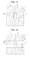
- FIG. 11 is a view of the cross section taken at the line IV-IV in FIG. 10 .
- FIG. 12 is a view of the cross section taken at the line V-V in FIG. 10 .
- the speaker system in accordance with an one embodiment of the present invention is composed of a speaker device, and a cabinet including a speaker-fixation wall to which the speaker device is to be affixed, an opposing wall that opposes to the speaker-fixation wall, and mutually opposing two pairs of side walls provided between the speaker-fixation wall and the opposing wall.
- the side wall of the cabinet is provided with a first duct that communicates with the interior space of the cabinet.
- a first opening that makes the interior space of the cabinet communicated with the inlet of the first duct is also provided at an area that encompasses a central portion of one side wall in the one pair of side walls having a shorter mutual distance therebetween in the two pairs of side walls.
- the first opening is allowed to be provided at a portion corresponding to an arc-shaped portion of the standing wave having low frequency being prone to exert influence on the frequency characteristic of a speaker, that is, the portion at which the sound pressure of standing wave is minimized, whereby the speaker system becomes to be less susceptible to the influence of the standing wave.
- the first duct may be made extended along the side wall through which the first opening is provided, and the outlet of the first duct may be provided at a further backward position in the sound-wave-radiation direction than the inlet thereof. Thereby, the sound that has passed through the first duct is allowed to be radiated backwardly in the sound-wave-radiation direction.
- a second duct that communicates with the interior space of the cabinet is provided, and a second opening that makes the interior space of the cabinet communicated with the inlet of the second duct may be provided at an area that encompasses a central portion of the other side wall in the one pair of side walls having a shorter mutual distance therebetween in the two pairs of side walls. Due to such a configuration, the second opening can be provided at a portion corresponding to an arc-shaped portion of the standing wave having low frequency being prone to exert influence on the frequency characteristic of a speaker, that is, the portion at which the sound pressure of standing wave is minimized, whereby the speaker system becomes to be less susceptible to the influence of the standing wave.
- At least one of the first duct and the second duct communicating with its inlet may be made extended along the side wall, through which the first opening or the second opening is provided, and the outlet of at least one of the first duct and the second duct may be provided at a further forward position in the sound-wave-radiation direction than the inlet thereof.
- the sound having passed through the first duct or the second duct is allowed to be radiated forwardly in the sound-wave-radiation direction.
- At least one of the first duct and the second duct communicating with its inlet may be made extended along the side wall through which the first opening or the second opening is provided, and the outlet of at least one of the first duct and the second duct may be provided at a further backward position in the sound-wave-radiation direction than the inlet thereof.
- the sound that has passed through the first duct is allowed to be radiated backwardly in the sound-wave-radiation direction.
- the first duct may be provided such that its square measures become larger towards the outlet from the inlet. Thereby, the sound wave can be radiated without causing unnecessary turbulent air or the like within the first duct.
- the first duct may be provided such that its widthwise sizes become larger in a direction parallel to the side wall through which the first opening is provided, and such that its widthwise sizes maintain a constant value in a direction intersecting with the side wall through which the first opening is provided.
- the square measures of the first duct are allowed to be larger while its widthwise sizes intersecting with the side wall through which the first opening is provided, are maintained in constant.
- At least one of the first duct and the second duct may be provided such that its widthwise sizes become larger towards the outlet from the inlet in a direction parallel to the side wall through which the first opening or the second opening is provided, and such that its widthwise sizes in a direction intersecting with the side wall through which the first opening or the second opening is provided, maintain a constant value.
- the square measures of the second duct may be made lager towards the outlet from the inlet while its widthwise sizes intersecting with the side wall through which the second opening is provided, are kept in constant.
- the peripheral portion opposing in a direction extending from the inlet to the outlet may be provided so as to be positioned in closer proximity to each other as approaching to the central portion. Thereby, the sound wave is allowed to be radiated without causing unnecessary turbulent air or the like within the first duct.
- the peripheral portion opposing in a direction extending from the inlet to the outlet of the first duct or the second duct may be provided so as to be positioned in closer proximity to each other as approaching to the central portion. Thereby, the sound wave can be radiated without causing unnecessary turbulent air or the like within the first duct or the second duct.
- the speaker system 1 in the first example is composed of a speaker device 2 , and a cabinet 3 having a rectangular parallelepiped shape, to which the speaker device 2 is affixed.
- the cabinet 3 is composed of a front wall 31 as a speaker-fixation wall to which the speaker device 2 is affixed, a rear wall 32 as an opposing wall opposing to the front wall 31 , and two pairs of side walls 33 and 34 , and side walls 35 and 36 , arranged between the front wall 31 and the rear wall 32 .
- the above-mentioned two speaker devices 2 are mounted side by side on an inner surface thereof.
- the front wall 31 is formed in a rectangular shape elongated in a direction in which the two speaker devices 2 are arranged.
- the rear wall 32 is formed in a rectangular shape elongated in a direction in which the two speaker devices 2 are arranged in a similar manner as the front wall 31 .
- the above-mentioned arrangement direction is the vertical direction
- the opposing direction in which the front wall 31 and the rear wall 32 opposes to each other is the front to rear direction
- a direction intersecting with both the arrangement direction and the front to rear direction is the crosswise direction.
- Each of the side walls 33 to 36 is provided so as to stand towards peripheral portion of the rear wall 32 from the peripheral portion of the front wall 31 .
- Side walls 33 and 34 are respectively provided so as to stand from the peripheral portion of the front wall 31 extending in the vertical direction of the front wall 31 , and oppose to each other in the crosswise direction.
- These side walls 33 and 34 are formed in substantially the same shape having an equivalent square measure.
- the side walls 35 and 36 are provided so as to stand from the peripheral portion extending in the crosswise direction of the front wall 31 and oppose to each other in the vertical direction.
- These side walls 35 and 36 are also formed in substantially the same shape having an equivalent square measure.
- the distance between the side walls 33 and 34 is designed so as to be shorter than the distance between the side walls 35 and 36 . That is, the side walls 33 and 34 correspond to the one pair of side walls having shorter mutual distance therebetween in the two pairs of the side walls 33 and 34 , and the side walls 35 and 36 .
- a first duct 34 A communicating with the interior space of the cabinet 3 which constitutes a space surrounded by the walls 31 to 36 .
- the first duct 34 A is designed so as to pass the low tones generated in the rearward side in the front to rear direction of the speaker device 2 therethrough to radiate towards the outside of the cabinet 3 .
- the first duct 34 A is extended in the front to rear direction along the side wall 34 , and its outlet is provided at both the further forward side (i.e., the sound-wave-radiation direction side) and the further rearward side (i.e., the reverse side, reverse to sound-wave-radiation direction). That is, the front wall 31 and the rear wall 32 are respectively provided with an opening, that serves as the outlet of the first duct 34 A.
- the above-described cross section in the first duct 34 A is formed in the rectangular shape elongated in the vertical direction, and is provided so as to maintain a substantially constant square measure towards the outlet from the inlet.
- a first opening 34 B making the interior space of the cabinet 3 communicated with the inlet of the first duct 34 A.
- the first opening 34 B is, as shown in FIG. 4 , formed in a rectangular shape elongated in the vertical direction.
- the first opening 34 B has the same height as the first duct 34 A in the vertical direction of the first duct 34 A.
- the low tones radiated from the rearward side with respect to the speaker device 2 enter into the first duct 34 A from the first opening 34 B as shown in FIG. 5 , and are radiated towards the outside of the cabinet 3 from the openings provided in the front wall 31 and the rear wall 32 through the first duct 34 A.
- the standing wave generated in the interior space of the above-described cabinet 3 will be described with reference to FIG. 6 .
- a phenomenon is occurred, that has been known as sympathetic vibration or resonance, by means of a formation of the two walls (ends) that are perpendicular to the traveling direction of the one-dimensional wave or the plane wave.
- a wave having been reflected at the one end is reflected again at the other end. This repetition of the reflection causes a standing wave whose amplitude is drastically amplified.
- the cabinet 3 having a rectangular parallelepiped shape as described above, three pairs of the front wall 31 and the rear wall 32 , the side wall 33 and the side wall 34 , and the side wall 35 and the side wall 36 oppose to one another. Then, standing waves W 1 to W 3 are respectively generated between the mutually opposing the front wall 31 and the rear wall 32 , between the side wall 33 and the side wall 34 , and between the side wall 35 and the side wall 36 . As shown in FIG. 6A , the standing wave W 1 is generated such that the side wall 35 and the side wall 36 as fixed ends are to serve as nodes, and the central portion between the side wall 35 and the side wall 36 is to serve as an arc-shaped portion.
- the standing wave W 2 is generated such that the front wall 31 and the rear wall 32 as fixed ends are to serve as nodes and the central portion between the front wall 31 and the rear wall 32 is to serve as an arc-shaped portion.
- a standing wave W 3 is generated such that the side wall 33 and the side wall 34 as fixed ends are to serve as nodes and the central portion between the side wall 33 and the side wall 34 is to serve as an arc-shaped portion.
- the distance between the side walls 35 and 36 becomes the longest
- the distance between the front wall 31 and the rear wall 32 becomes the next longest
- the distance between the side walls 33 and 34 is the shortest.
- the standing wave W 1 has the lowest one
- the standing wave W 2 has the next lowest one
- the standing wave W 3 has the highest one.
- the marks L 1 indicates the frequency characteristic of the first duct 34 A
- the mark L 2 indicates the frequency characteristic of the overall speaker system 1 .
- the first duct 34 A is a duct from which low tones are derived. Hence, the frequency characteristic of the first duct 34 A is observed as having a high sound pressure within the low frequency wave range, whereas is observed as having a low sound pressure within the high frequency wave range.
- the frequency characteristic of the first duct 34 A at the frequency of each of the standing waves W 1 to W 3 is made disturbed, so as to exert its influence on the frequency characteristic of the speaker system 1 . That is, if it were not for the standing waves W 1 to W 3 , the frequency characteristic of the first duct 34 A shall be, as indicated by the mark L 1 in the drawing, such that the sound pressure is gradually reduced as reaching high frequency. Actually nonetheless, the frequency characteristic is disturbed due to the influence of the standing waves W 1 to W 3 as indicated by the marks N 11 to N 13 .
- the marks N 11 , N 12 , and N 13 respectively show the turbulence in the frequency characteristic of the first duct 34 A due to the influence of the standing waves W 1 , W 2 , and W 3 .
- the sound pressure of the first duct 34 A is stayed high therewith, the speaker system 1 is prone to be influenced thereby in its frequency characteristic.
- the influence on the frequency characteristic of the speaker system 1 has been scarcely observed as well.
- the frequency characteristic of the speaker system 1 shows, as indicated by the mark L 2 in the figure, a substantially plain characteristic in the high-frequency range.
- a turbulence is caused in the frequency characteristic as indicated by the marks N 21 and N 22 .
- the marks N 21 and N 22 respectively show a turbulence in the frequency characteristic of the speaker system 1 due to the influence of the standing waves W 1 and W 2 .
- a turbulence in the frequency characteristic due to the influence of the standing wave W 3 has been scarcely observed.
- the first opening 34 B is provided at the area encompassing the central portion of the side wall 34 as the one side wall in the side walls 33 and 34 having a short mutual distance therebetween.
- the first opening 34 B can be provided at the portions corresponding to the arc-shaped portions of the low standing waves W 1 and W 2 , which are likely to exert influence on the frequency characteristic of the speaker system 1 , that are the portions at which the sound pressures of the standing wave W 1 and W 2 take the minimum value, thereby becoming less susceptible to the influence of the standing waves W 1 to W 3 .
- FIG. 6A the first opening 34 B can be provided at the portions corresponding to the arc-shaped portions of the low standing waves W 1 and W 2 , which are likely to exert influence on the frequency characteristic of the speaker system 1 , that are the portions at which the sound pressures of the standing wave W 1 and W 2 take the minimum value, thereby becoming less susceptible to the influence of the standing waves W 1 to W 3 .
- the first opening 34 B is provided at the portion corresponding to the node of the standing wave W 3 , that is the portion at which the sound pressure of the standing wave W 3 takes the maximum value, it should be noted that the original influence by the standing wave W 3 having high frequency can be neglected as aforementioned.
- the first duct 34 A is extended along the side wall 34 through which the first opening 34 B is provided, and the outlet of the first duct 34 A is provided at a further forward position (i.e., sound-wave-radiation direction side) than the inlet of the first duct 34 A with respect to the speaker device 2 .
- the sound having passed through the first duct 34 A is allowed to be radiated forwardly in the sound-wave-radiation direction.
- the outlet of the first duct 34 A is provided at a further backward position (i.e., reverse side, reverse to the sound-wave-radiation direction side) than the inlet of the first duct 34 A with respect to the speaker device 2 .
- the sound having passed through the first duct 34 A is allowed to be radiated backwardly in the sound-wave-radiation direction.
- the first duct 34 A has an identical square measure at every position between the inlet and the outlet, and the first opening 34 B is formed in a rectangular shape
- the present invention is not limited thereto.
- the first opening 34 B may be provided so as to have larger square measures towards the outlet from the inlet of the first duct 34 A.
- the sound wave can be radiated without causing unnecessary turbulent air or the like within the first duct 34 A.
- the vicinity area of the inlet of the first duct 34 A may be designed such that the square measures thereof become smaller towards the outlet, and afterward, its square measures become larger towards the outlet.
- the first duct 34 A has wider widthwise sizes (i.e., widthwise size in a direction parallel to the side wall 34 ) in the vertical direction towards the outlet from the inlet, and has a constant widthwise size (i.e., direction intersecting with the side wall 34 ) in the crosswise direction towards the outlet from the inlet.
- widthwise sizes i.e., widthwise size in a direction parallel to the side wall 34
- constant widthwise size i.e., direction intersecting with the side wall 34
- the first opening 34 B may be formed, as shown in FIG. 8 and FIG. 9A , such that the peripheral portions opposing in the front to rear direction (i.e., direction extending from the inlet towards the outlet of the first duct 34 A) to each other are located closer to each other as approaching to the central portion. Thereby, the sound wave is allowed to be radiated without causing unnecessary turbulent air or the like within the first duct 34 A.
- the first duct 34 A may be formed in a horns-like shape
- the first opening 34 B may be formed in a rectangular shape as in the first example.
- the speaker system 1 in the second example is described with reference to FIG. 10 to FIG. 12 .
- the difference between the first example and the second example lies in that a second duct 33 A and a second opening 33 B are provided at the side wall 33 that is the other one in the pair of the side walls 33 and 34 having smaller mutual distance therebetween.
- the second duct 33 A similarly to the first duct 34 A, radiates low tones generated from the rearward side in the front to rear direction through the interior space of the cabinet 3 towards the outside of the cabinet 3 .
- the second duct 33 A is also extended in the front to rear direction along the side wall 33 , and its outlets are respectively provided closer to the forward side and the rearward side than the inlet of the second duct 33 A. That is, at the front wall 31 and the rear wall 32 , openings serving as the outlets of the second duct 33 A are respectively provided.
- the cross section of the above-described second duct 33 A is formed in a rectangular shape elongated in the vertical direction, and is also provided so as to have a constant square measure towards the outlet from the inlet.
- the second opening 33 B making the interior space of the cabinet 3 communicated with the inlet of the second opening 33 A at the area encompassing its central portion.
- the second opening 33 B is provided, as shown in FIG. 11 , in a rectangular shape elongated in the vertical direction.
- the second opening 33 B has the same height as the second duct 33 A in the vertical direction.
- the second opening 33 B at the area encompassing the central portion of the side wall 33 , the portions corresponding to the arc-shaped portions of the standing waves W 1 and W 2 having low frequency are lead to the second duct 33 A, the influence of the standing waves W 1 to W 3 can be reduced in a similar manner.
- the second duct 33 A may be designed so as to have larger square measures from the inlet towards the outlet.
- the second duct 33 A may be provided so as to have larger widthwise sizes towards the outlet from the inlet in the vertical direction, and so as to have a constant widthwise size towards the outlet from the inlet.
- the second opening 33 B may be designed, in a similar manner to the first opening 34 B as shown in FIG. 8 and FIG. 9 , such that in the second opening 33 B, the peripheral portions opposing in the direction extending from the inlet towards the outlet are closer as approaching to the central portion.
- the outlets of the first duct 34 A and the second duct 33 A are respectively provided in the two areas of the forward side and the rearward side, the present invention is not necessarily limited thereto.
- the outlet of the first duct 34 A and the second duct 33 A may be provided at either one of the forward side or the rearward side.
- the cabinet 3 is formed in a rectangular parallelepiped shape, the present invention is not necessarily limited thereto.
- the cabinet 3 only have to be formed in any substantially rectangular parallelepiped shapes, for example, may be formed in a shape in which portion(s) of the corners of the rectangular parallelepiped shape has been lost.
- the cabinet 3 is provided with two speaker devices 2 , the present invention is not necessarily limited thereto. Only one speaker device 2 may also be affixed to the cabinet 3 , or three or more than three speaker devices 2 may also be affixed to the cabinet 3 .
- the example described above merely exemplifies a representative aspect of the present invention.
- the present invention is not necessarily limited to the embodiment. That is, the present invention may be modified to be implemented in various forms without departing from the gist of the present invention.
Landscapes
- Health & Medical Sciences (AREA)
- Otolaryngology (AREA)
- Physics & Mathematics (AREA)
- Engineering & Computer Science (AREA)
- Acoustics & Sound (AREA)
- Signal Processing (AREA)
- Details Of Audible-Bandwidth Transducers (AREA)
- Obtaining Desirable Characteristics In Audible-Bandwidth Transducers (AREA)
Abstract
Description
- 1 speaker system
- 2 speaker device
- 3 cabinet
- 31 front wall (speaker-fixation wall)
- 32 rear wall (opposing walls)
- 33 to 36 side wall
- 33A second duct
- 33B second opening
- 34A first duct
- 34B first opening
Claims (11)
Applications Claiming Priority (1)
| Application Number | Priority Date | Filing Date | Title |
|---|---|---|---|
| PCT/JP2014/059362 WO2015145774A1 (en) | 2014-03-28 | 2014-03-28 | Speaker system |
Publications (2)
| Publication Number | Publication Date |
|---|---|
| US20170127164A1 US20170127164A1 (en) | 2017-05-04 |
| US9854339B2 true US9854339B2 (en) | 2017-12-26 |
Family
ID=54194358
Family Applications (1)
| Application Number | Title | Priority Date | Filing Date |
|---|---|---|---|
| US15/129,082 Active US9854339B2 (en) | 2014-03-28 | 2014-03-28 | Speaker system |
Country Status (3)
| Country | Link |
|---|---|
| US (1) | US9854339B2 (en) |
| JP (1) | JP6243513B2 (en) |
| WO (1) | WO2015145774A1 (en) |
Cited By (1)
| Publication number | Priority date | Publication date | Assignee | Title |
|---|---|---|---|---|
| US10602249B2 (en) | 2018-05-03 | 2020-03-24 | Samsung Electronics Co., Ltd. | Electronic device conduit structure and electronic device including same |
Families Citing this family (2)
| Publication number | Priority date | Publication date | Assignee | Title |
|---|---|---|---|---|
| US11330364B1 (en) * | 2021-01-12 | 2022-05-10 | Robert Bosch Gmbh | Ported speaker assembly |
| WO2025022701A1 (en) * | 2023-07-25 | 2025-01-30 | パナソニックIpマネジメント株式会社 | Speaker device |
Citations (10)
| Publication number | Priority date | Publication date | Assignee | Title |
|---|---|---|---|---|
| JPH04126488A (en) | 1990-09-18 | 1992-04-27 | Canon Inc | Digital signal processing unit |
| JPH0638284A (en) | 1992-07-14 | 1994-02-10 | Pioneer Electron Corp | Phase inversion type speaker equipment |
| JPH0662484A (en) | 1992-08-05 | 1994-03-04 | Mitsubishi Electric Corp | Bass reflex speaker system |
| JP2000295682A (en) | 1999-04-06 | 2000-10-20 | Pioneer Electronic Corp | Acoustic casing and sound absorptive panel |
| US6324292B1 (en) * | 1998-10-14 | 2001-11-27 | Pioneer Corporation | Speaker apparatus |
| US6654472B1 (en) | 1999-06-26 | 2003-11-25 | Lg Electronics Inc. | Speaker system in display |
| US20040131219A1 (en) * | 2003-01-07 | 2004-07-08 | Polk Matthew S. | Ported loudspeaker system and method with reduced air turbulence, bipolar radiation pattern and novel appearance |
| US6912390B2 (en) * | 2000-12-22 | 2005-06-28 | Telefonaktiebolaget Lm Ericsson | Connection handling in SRNC relocation |
| US7181039B2 (en) * | 2004-01-30 | 2007-02-20 | Step Technologies Inc. | Thermal chimney equipped audio speaker cabinet |
| US8170255B2 (en) * | 2006-02-01 | 2012-05-01 | Fei Company | Enclosure for acoustic insulation of an apparatus contained within said enclosure |
Family Cites Families (5)
| Publication number | Priority date | Publication date | Assignee | Title |
|---|---|---|---|---|
| WO1991019406A1 (en) * | 1990-05-25 | 1991-12-12 | Mitsubishi Denki Kabushiki Kaisha | Speaker system |
| JP2580378Y2 (en) * | 1991-05-09 | 1998-09-10 | オンキヨー株式会社 | Speaker box |
| US5757946A (en) * | 1996-09-23 | 1998-05-26 | Northern Telecom Limited | Magnetic fluid loudspeaker assembly with ported enclosure |
| US7207413B2 (en) * | 2003-06-02 | 2007-04-24 | Tbi Audio Systems Llc | Closed loop embedded audio transmission line technology for loudspeaker enclosures and systems |
| JP6044164B2 (en) * | 2011-09-09 | 2016-12-14 | ヤマハ株式会社 | Sound equipment |
-
2014
- 2014-03-28 JP JP2016509864A patent/JP6243513B2/en active Active
- 2014-03-28 WO PCT/JP2014/059362 patent/WO2015145774A1/en not_active Ceased
- 2014-03-28 US US15/129,082 patent/US9854339B2/en active Active
Patent Citations (10)
| Publication number | Priority date | Publication date | Assignee | Title |
|---|---|---|---|---|
| JPH04126488A (en) | 1990-09-18 | 1992-04-27 | Canon Inc | Digital signal processing unit |
| JPH0638284A (en) | 1992-07-14 | 1994-02-10 | Pioneer Electron Corp | Phase inversion type speaker equipment |
| JPH0662484A (en) | 1992-08-05 | 1994-03-04 | Mitsubishi Electric Corp | Bass reflex speaker system |
| US6324292B1 (en) * | 1998-10-14 | 2001-11-27 | Pioneer Corporation | Speaker apparatus |
| JP2000295682A (en) | 1999-04-06 | 2000-10-20 | Pioneer Electronic Corp | Acoustic casing and sound absorptive panel |
| US6654472B1 (en) | 1999-06-26 | 2003-11-25 | Lg Electronics Inc. | Speaker system in display |
| US6912390B2 (en) * | 2000-12-22 | 2005-06-28 | Telefonaktiebolaget Lm Ericsson | Connection handling in SRNC relocation |
| US20040131219A1 (en) * | 2003-01-07 | 2004-07-08 | Polk Matthew S. | Ported loudspeaker system and method with reduced air turbulence, bipolar radiation pattern and novel appearance |
| US7181039B2 (en) * | 2004-01-30 | 2007-02-20 | Step Technologies Inc. | Thermal chimney equipped audio speaker cabinet |
| US8170255B2 (en) * | 2006-02-01 | 2012-05-01 | Fei Company | Enclosure for acoustic insulation of an apparatus contained within said enclosure |
Non-Patent Citations (1)
| Title |
|---|
| International Search Report, PCT/JP2014/059362, dated Jun. 24, 2014. |
Cited By (1)
| Publication number | Priority date | Publication date | Assignee | Title |
|---|---|---|---|---|
| US10602249B2 (en) | 2018-05-03 | 2020-03-24 | Samsung Electronics Co., Ltd. | Electronic device conduit structure and electronic device including same |
Also Published As
| Publication number | Publication date |
|---|---|
| US20170127164A1 (en) | 2017-05-04 |
| WO2015145774A1 (en) | 2015-10-01 |
| JPWO2015145774A1 (en) | 2017-04-13 |
| JP6243513B2 (en) | 2017-12-06 |
Similar Documents
| Publication | Publication Date | Title |
|---|---|---|
| US9635454B2 (en) | Bass-reflex speaker cabinet having a recessed port | |
| KR101780911B1 (en) | Loudspeaker module | |
| US9854339B2 (en) | Speaker system | |
| US9282398B2 (en) | Speaker system having wide bandwidth and wide high-frequency dispersion | |
| CN104700827B (en) | Wideband sound absorbent perforated structure | |
| CN103220608A (en) | Loudspeaker module | |
| EP1996006A2 (en) | Apparatus with a built-in loud speaker and LCD television receiver | |
| USD690289S1 (en) | Antenna | |
| CN104053087A (en) | Tubular body, bass reflex port, and acoustic apparatus | |
| US3882962A (en) | Loudspeaker equipment | |
| US9602928B2 (en) | Speaker system having a sound collection unit for combining sound waves | |
| US20150071473A1 (en) | Transmission line loudspeaker | |
| CN117957857A (en) | Horn Loaded Loudspeaker | |
| US9473848B2 (en) | Transmission line loudspeaker | |
| WO2018123727A1 (en) | Speaker device and speaker cabinet | |
| US10085093B2 (en) | Loudspeaker arrangement | |
| CN205142474U (en) | Loudspeaker box | |
| CN105165025A (en) | speaker | |
| CN104953230B (en) | Antenna Fixing Structure | |
| CN104137328B (en) | Directional coupler | |
| JP5867705B2 (en) | Speaker cabinet and speaker | |
| USD862592S1 (en) | Poster board | |
| USD884513S1 (en) | Expandable measuring gauge | |
| CN203033169U (en) | Upper cushion block for air-conditioner package device and air-conditioner package device | |
| CN203870970U (en) | Thick sheet assembly used for silencer |
Legal Events
| Date | Code | Title | Description |
|---|---|---|---|
| AS | Assignment |
Owner name: TECHNICAL AUDIO DEVICES LABORATORIES, INC., JAPAN Free format text: ASSIGNMENT OF ASSIGNORS INTEREST;ASSIGNORS:NAGATANI, TORU;SUENAGA, TOMOHIRO;TAKEDA, HARUKI;AND OTHERS;REEL/FRAME:039855/0390 Effective date: 20160711 Owner name: TOHOKU PIONEER CORPORATION, JAPAN Free format text: ASSIGNMENT OF ASSIGNORS INTEREST;ASSIGNORS:NAGATANI, TORU;SUENAGA, TOMOHIRO;TAKEDA, HARUKI;AND OTHERS;REEL/FRAME:039855/0390 Effective date: 20160711 Owner name: PIONEER CORPORATION, JAPAN Free format text: ASSIGNMENT OF ASSIGNORS INTEREST;ASSIGNORS:NAGATANI, TORU;SUENAGA, TOMOHIRO;TAKEDA, HARUKI;AND OTHERS;REEL/FRAME:039855/0390 Effective date: 20160711 |
|
| STCF | Information on status: patent grant |
Free format text: PATENTED CASE |
|
| MAFP | Maintenance fee payment |
Free format text: PAYMENT OF MAINTENANCE FEE, 4TH YEAR, LARGE ENTITY (ORIGINAL EVENT CODE: M1551); ENTITY STATUS OF PATENT OWNER: LARGE ENTITY Year of fee payment: 4 |
|
| MAFP | Maintenance fee payment |
Free format text: PAYMENT OF MAINTENANCE FEE, 8TH YEAR, LARGE ENTITY (ORIGINAL EVENT CODE: M1552); ENTITY STATUS OF PATENT OWNER: LARGE ENTITY Year of fee payment: 8 |