US9851294B1 - Integrated mid-infrared, far infrared and terahertz optical Hall effect (OHE) instrument, and method of use - Google Patents
Integrated mid-infrared, far infrared and terahertz optical Hall effect (OHE) instrument, and method of use Download PDFInfo
- Publication number
- US9851294B1 US9851294B1 US14/545,816 US201514545816A US9851294B1 US 9851294 B1 US9851294 B1 US 9851294B1 US 201514545816 A US201514545816 A US 201514545816A US 9851294 B1 US9851294 B1 US 9851294B1
- Authority
- US
- United States
- Prior art keywords
- sample
- stage
- data
- obtaining
- magnetic field
- Prior art date
- Legal status (The legal status is an assumption and is not a legal conclusion. Google has not performed a legal analysis and makes no representation as to the accuracy of the status listed.)
- Active, expires
Links
- 0 C=BrC*=C1C=CC=C1 Chemical compound C=BrC*=C1C=CC=C1 0.000 description 1
Images


Classifications
-
- G—PHYSICS
- G01—MEASURING; TESTING
- G01N—INVESTIGATING OR ANALYSING MATERIALS BY DETERMINING THEIR CHEMICAL OR PHYSICAL PROPERTIES
- G01N21/00—Investigating or analysing materials by the use of optical means, i.e. using sub-millimetre waves, infrared, visible or ultraviolet light
- G01N21/17—Systems in which incident light is modified in accordance with the properties of the material investigated
- G01N21/21—Polarisation-affecting properties
- G01N21/211—Ellipsometry
-
- G—PHYSICS
- G01—MEASURING; TESTING
- G01J—MEASUREMENT OF INTENSITY, VELOCITY, SPECTRAL CONTENT, POLARISATION, PHASE OR PULSE CHARACTERISTICS OF INFRARED, VISIBLE OR ULTRAVIOLET LIGHT; COLORIMETRY; RADIATION PYROMETRY
- G01J4/00—Measuring polarisation of light
- G01J4/04—Polarimeters using electric detection means
-
- G—PHYSICS
- G01—MEASURING; TESTING
- G01N—INVESTIGATING OR ANALYSING MATERIALS BY DETERMINING THEIR CHEMICAL OR PHYSICAL PROPERTIES
- G01N27/00—Investigating or analysing materials by the use of electric, electrochemical, or magnetic means
- G01N27/72—Investigating or analysing materials by the use of electric, electrochemical, or magnetic means by investigating magnetic variables
-
- G—PHYSICS
- G01—MEASURING; TESTING
- G01N—INVESTIGATING OR ANALYSING MATERIALS BY DETERMINING THEIR CHEMICAL OR PHYSICAL PROPERTIES
- G01N21/00—Investigating or analysing materials by the use of optical means, i.e. using sub-millimetre waves, infrared, visible or ultraviolet light
- G01N21/17—Systems in which incident light is modified in accordance with the properties of the material investigated
- G01N21/21—Polarisation-affecting properties
- G01N21/211—Ellipsometry
- G01N2021/213—Spectrometric ellipsometry
-
- G—PHYSICS
- G01—MEASURING; TESTING
- G01N—INVESTIGATING OR ANALYSING MATERIALS BY DETERMINING THEIR CHEMICAL OR PHYSICAL PROPERTIES
- G01N21/00—Investigating or analysing materials by the use of optical means, i.e. using sub-millimetre waves, infrared, visible or ultraviolet light
- G01N21/17—Systems in which incident light is modified in accordance with the properties of the material investigated
- G01N21/25—Colour; Spectral properties, i.e. comparison of effect of material on the light at two or more different wavelengths or wavelength bands
- G01N21/31—Investigating relative effect of material at wavelengths characteristic of specific elements or molecules, e.g. atomic absorption spectrometry
- G01N21/35—Investigating relative effect of material at wavelengths characteristic of specific elements or molecules, e.g. atomic absorption spectrometry using infrared light
- G01N21/3581—Investigating relative effect of material at wavelengths characteristic of specific elements or molecules, e.g. atomic absorption spectrometry using infrared light using far infrared light; using Terahertz radiation
- G01N21/3586—Investigating relative effect of material at wavelengths characteristic of specific elements or molecules, e.g. atomic absorption spectrometry using infrared light using far infrared light; using Terahertz radiation by Terahertz time domain spectroscopy [THz-TDS]
Definitions
- the present invention relates to Hall Effect measurement systems, and more particularly to an integrated visual, mid-infrared, far-infrared and terahertz Optical Hall Effect (OHR) instrument, covering an ultra-wide spectral range from 3 cm ⁇ 1 to 7000 cm ⁇ 1 (0.1-210 THz or 0.4-870 meV), and methodology of its use in determining such as free charge carrier longitudinal and transverse effective masses, concentration, mobility and charge carrier type.
- OLR Optical Hall Effect
- One embodiment comprises sub-systems, including a magneto-cryostat-transfer sub-system that enables the usage of a magneto-cryostat sub-system with a visible, mid-infrared ellipsometer sub-system, and a far-infrared/terahertz ellipsometer sub-system.
- An electromagnetic beam (EM) providing Source sub-system can be applied to provide a variable angle-of-incidence, to a sample, in spectroscopic ellipsometers in reflection or transmission mode, and comprises, in a desired wavelength range, at least one light source and detector.
- the ellipsometer sub-systems can be operated in rotatable polarizer-sample-rotating-analyzer configuration granting access to the upper left 3 ⁇ 3 block of the normalized 4 ⁇ 4 Mueller matrix.
- the closed cycle magneto-cryostat sub-system provides sample temperatures between room temperature and 1.4 degrees K, and magnetic fields up to 8 T, enabling the detection of transverse and longitudinal magnetic field-induced birefringence, which can be enhanced by a resonance cavity effect.
- a preferred embodiment, which is focal in the present invention replaces the magneto cryostat with a smaller (0.8-1.6 T) permanent magnet, and results produced therewith are easier to obtain and apply, especially in less substantial lab settings.
- the Optical Hall Effect is a physical phenomenon which describes the occurrence of transverse and longitudinal magnetic field-induced birefringence, caused by the nonreciprocal magneto-optic response of electric charge carriers.
- the term (OHE) is used since the classic electrical Hall Effect (HE), and the (OHE) effect both find explanation within the Drude model.
- the term Optical Hall Effect (OHE) is used in analogy to the classic electrical Hall Effect as the electrical Hall effect and certain cases of (OHE) observation can be explained by extensions of the classic Drude model for the transport of electrons in matter, (eg. Metals).
- Drude's classic model is extended by a magnetic field and frequency dependency, describing the electron's momentum under the influence of the Lorentz force.
- the (OHE) allows determination of concentration, mobility, and effective mass of the free electrons as the (OHE) can be quantified in terms of the Mueller matrix, which characterizes the transformation of an electromagnetic wave's polarization state.
- the Mueller matrix is measured by Generalized Ellipsometry (GE), which allows for adjustment of the Angle and the Plane of Incidence a beam of electromagnetic radiation makes with respect to a sample surface, as well as rotation of a sample about a perpendicular to said sample surface. Further, during a (GE) measurement different polarization states of the incident light are prepared and their change upon reflection from or transmission through a sample is determined.
- GE Generalized Ellipsometry
- Optical Hall Effect (OHE) instruments conduct GE measurements on samples in high quasi-static magnetic fields, and detect the magnetic field induced changes of the Mueller matrix. Though several instruments with partial (OHE) capability are described in the literature, most thereof do not fulfill all desirable criteria for a true (OHE) instrument. For instance, in 1985 Nederpel and Martens, published an article, (see Review of Scientific Instruments, 56,687 (1985)), reported development of a single wavelength (444 nm) magneto-optical ellipsometer for use in the visible spectral range, but the instrument provided only low magnetic fields, (ie. B less than 50 mT).
- a THz time-domain spectroscopy based instrument capable of recording the complex reflection coefficients at magnetic B fields of about 0.5 T was described in 2004 by Ino et al., (see Phys. Rev. B 70, 155101, (2004)).
- a full 4 ⁇ 4 Mueller matrix in the terahertz-mid-infrared spectral range (20 to 4000 cm ⁇ 1 ) can be measured by an instrument described in 2013 by Stanislavchuk et al., (see Review of Scientific Instruments, 84, 023901, (2013)), but there the instrument was not designed for experiments with the sample exposed to external magnetic fields.
- the first full (OHE) instrument was developed and demonstrated in 2006 by Inventor herein, Hofmann, (see Review of Scientific Instruments, 77, 63902, (2006)) for the far-infrared (FIR) spectral range (30 to 650 cm ⁇ 1 ), which provided magnetic fields up to 6 T and allowed sample temperatures between 4.2 K and room temperature.
- This first full capability (OHE) instrument has since been successfully used to determine free charge carrier properties including effective mass parameters for a variety of material systems.
- (OHE) experiments were conducted in the terahertz (THz) spectral range, but were limited to room temperature and low magnetic fields (ie. B fields less than or equal to 1.8 T), and are subject of the invention disclosed herein.
- THz terahertz
- An (OHE) instrument for the MIR can detect the magneto-optic response of free charge carriers enhanced by phonon modes present in the spectral range above 600 cm ⁇ 1 , which applies to many substrate materials, SiC, Al 2 O 3 or GaN, as well as to many materials used for thin films, III-V nitride semiconductors Al 1-x Ga x N In 1-x N Al 1-x In x N or In 1-x Ga x N.
- inter-Landau-level transitions can be studied in the MIR spectral range with a MIR (OHE) instrument.
- the extension to the THz spectral range enables the detection of the (OHE) in samples with low carrier concentrations.
- the strongest magneto-optic response can be observed at the cyclotron resonance frequency, which typically lies in the microwave/THz spectral range for moderate magnetic fields, (eg. a few Tesla), and effective mass values comparable to the free electron mass.
- the present invention presents an (OHE) instrument that covers an ultra-wide spectral range from 3/cm to 7000/cm, (ie. 0.1-210 THz or 0.4-870 meV), which combines MIR, FIR and THz magneto-optic generalized ellipsometry in a single instrument.
- the preferred embodiment applies at least one permanent magnet with strength in the range of 0.6 to 1.8 T.
- the ellipsometer sub-systems used to actually achieve results reported herein were built in-house and operate in the rotating-analyzer configuration, (a non-limiting election), and are capable of determining the normalized upper 3 ⁇ 3 block of the sample Mueller matrix.
- Said (OHE) provides insight into free charge carrier properties such as effective mass (m), mobility (u), and carrier concentration (N) of complex and even layered samples.
- m effective mass
- u mobility
- N carrier concentration
- a Te-doped, n-type GaAs substrate served as a model system for the FIR spectral range of the FIR/THz ellipsometer sub-system.
- the (OHE) signal originating from valence band electrons in a bulk material were noted, and the concentration, mobility, and effective mass parameters of the valence band electrons determined.
- HEMT high electron mobility transistor structure
- the evaluation of physically relevant parameters from the (OHE) requires the experimental observation and quantification of the OHE, and a physical model to analyze (OHE) data.
- the (OHE) is quantified in terms of the Mueller matrix M OHE by employing Generalized Ellipsometry (GE).
- GE Generalized Ellipsometry
- the physical model which is used to analyze the observed transverse and longitudinal magneto-optic birefringence of the (OHE) is based on the magneto-optic dielectric tensor ⁇ oeh (B), which is a function of the slowly varying external magnetic field B.
- the magneto-optic permittivity of a material within a given sample described by ⁇ B may originate from the response of bound and unbound charge carriers subjected to the magnetic field and the action of the Lorentz force.
- the magneto-optic response of a sample subjected to the integrated MIR, FIR and THz (OHE) instrument, and which is addressed herein is represented by a generally anisotropic and nonreciprocal tensor.
- ⁇ n 1 2 ⁇ ( ( X ++ ⁇ X - ) i ⁇ ( X + - X - ) 0 - i ( X ++ ⁇ X - X ++ ⁇ X - 0 0 0 0 ) ( 3 )
- the dielectric tensor for charge carriers subject to the external magnetic field B can be expressed as:
- ⁇ L ( ( ⁇ ⁇ L X ) 0 0 0 ⁇ ⁇ L Z 0 0 0 ⁇ ⁇ L Z ) ( 7 )
- ⁇ LO,kj , ⁇ LO,kj , ⁇ TO,kj , and ⁇ TO,kj denote the k(x,y,z) component of the frequency and the broadening values of the j th longitudinal optical (LO) and transverse optical (TO) phonon modes, respectively, while the index j runs over l modes.
- ⁇ P nq 2 m ⁇ ⁇ ⁇ 0 is the plasma frequency
- ⁇ D permittivity function of the isotropic Drude dielectric function.
- the magneto-optic contribution to the dielectric tensor ⁇ B D for isotropic effective masses and conductivities can be expressed, using Eq. 3, through polarizability functions for right- and left-handed circularly polarized light:
- ⁇ ⁇ e ⁇ ⁇ i ⁇ ⁇ ⁇ ⁇ ⁇ k ⁇ A k ⁇ 2 - ⁇ 0 , k 2 - i ⁇ ⁇ ⁇ k ⁇ ⁇ , ( 11 )
- a k , ⁇ 0,k , and ⁇ k are amplitude, transition energy, and broadening parameter of the k th inter Landau-level transition, respectively, which in general depend on the magnetic field.
- the phase factor was introduced here to describe the experimentally observed line shapes of all Mueller matrix elements.
- GE Generalized ellipsometry
- SE isotropic ellipsometry
- This section describes the Jones vector/Mueller matrix formalism used in GE, aspects of Mueller matrix and (OHE) data, and the acquisition of Mueller matrix data.
- the real-valued 4 ⁇ 4 Mueller matrix M describes the change of electromagnetic plane wave properties (intensity, polarization state), expressed by a Stokes vector S, upon change of the coordinate system or the interaction with a sample, optical element, or any other matter:
- the Mueller matrix can be decomposed in 4 sub-matrices, where the matrix elements of the two off-diagonal-blocks:
- [ M ⁇ ⁇ 13 M ⁇ ⁇ 14 M ⁇ ⁇ 23 M ⁇ ⁇ 24 ] [ M ⁇ ⁇ 21 M ⁇ ⁇ 14 M ⁇ ⁇ 41 M ⁇ ⁇ 42 ] mainly contain information about p-s-polarization mode conserving processes. It is to be appreciated that p- to p-polarization mode conversion is defined as the transfer of energy from the p-polarized channel of an electromagnetic plane wave to the s-polarized channel, or vice versa.
- Polarization mode conversion can appear when the p-s-coordinate system is different for S in and S out , or, when a sample shows birefringence, for example.
- polarization mode conversion appears if the dielectric tensor of a sample possesses non-vanishing off-diagonal elements. Therefore, in Mueller matrix data from optically isotropic samples, ideally all off-diagonal-block elements vanish, while, for example, magneto-optic birefringence can cause non-zero off-diagonal-block elements in the Mueller matrix.
- (OHE) data Mueller matrix data from an (OHE) experiment [Eq.
- M OHE ⁇ M ( ⁇ B+0 + ⁇ ⁇ B ) (13)
- M 0 M( ⁇ B ⁇ 0 ) is the Mueller matrix of the zero field experiment
- ⁇ M( ⁇ B ⁇ 0 , ⁇ ⁇ B ) is the magnetic field induced change of the Mueller matrix.
- ⁇ M + ⁇ M ⁇ ⁇ M ( ⁇ B ⁇ 0 , ⁇ +B ) ⁇ M ( ⁇ B ⁇ 0 , ⁇ ⁇ B ), (15) that can be used to inspect symmetry properties of magneto-optic Mueller matrix data, and can help to improve the sensitivity to magnetic field dependent model parameters during data analysis.
- Mueller Matrix Data Acquisition (GE) GE
- Spectroscopic ellipsometers can be categorized according to their polarization optical components and operation principles, where different subsets of Mueller matrix elements may be accessible. For example Spectroscopic ellipsometers can be classified into two categories: (i) polarizer-sample+rotating analyzer ellipsometers (PSA R ) or rotating-polarizer+sample-analyzer (P R SA) configurations, capable of measuring the upper left 3 ⁇ 3 block of the Mueller matrix; and (ii) rotating compensator(s) ellipsometers (RCE) in polarizer-sample-rotating-compensator-analyzer (PSC R A) or polarizer-rotating-compensator-sample-analyzer (PC R SA) configuration, capable of measuring the upper left 3 ⁇ 4 or 4 ⁇ 3 block of the Mueller matrix, respectively.
- PSA R polarizer-sample+rotating analyzer ellipsometers
- P R SA rotating-polarizer+sa
- Ellipsometry is generally an indirect experimental technique. Therefore, in general, ellipsometric data analysis invokes model calculations to determine physical parameters in dielectric tensors or the thickness of layers, for instance. Sequences of homogeneous layers with smooth and parallel interfaces are assumed in order to calculate the propagation of light through a layered sample, by the 4 ⁇ 4 matrix formalism. To best match the generated data with experimental results, parameters with significance physical model parameter in dielectric tensors, layer thicknesses etc. are varied and Mueller matrix data is calculated for all spectral data points, angles of incidence and magnetic fields. During the mean square error (MSE) regression, the generated Mueller matrix data M ijk G , is compared with the experimental Mueller matrix data M ijk B , and their match is quantified by the MSE:
- MSE mean square error
- S, K and ⁇ M ij,k G denotes the total number of spectral data points, the total number of parameters varied during the non-linear regression process, the number experimentally determined columns and rows of the Mueller matrix and the standard deviation of M ⁇ I,j,k ⁇ , obtained during the experiment, respectively.
- the Levenberg-Marquardt fitting algorithm For fast convergence of the MSE regression, the Levenberg-Marquardt fitting algorithm is used.
- the MSE regression is interrupted when the decrease in the MSE is smaller than a set threshold and the determined parameters are considered as best model parameters.
- the sensitivity and possible correlation of the varied parameters is checked and, if necessary, the model is changed and the process is repeated.
- Eventually values for parameters in the mathematical model of the sample being characterized are arrived at and represent very reliable insight to actual physical values.
- ellipsometry can provide results that allow direct analytical solutions for such as concentration and mobility of charge carriers based on off diagonal Jones or Mueller Matrix element value slopes, as a function of an applied magnetic field.
- concentration and mobility of charge carriers based on off diagonal Jones or Mueller Matrix element value slopes, as a function of an applied magnetic field.
- typical approach to determining at least one of the free charge carrier longitudinal and/or transversal effective masses, and/or concentration, and/or mobility and/or type from said anisotropic values for said at least a partial Jones or Mueller Matrix determining involves use of mathematical regression onto a model of the sample and ellipsometer or polarimeter system used to evaluate the Jones or Mueller Matrix elements, it is possible under certain circumstances to arrive at concentration and mobility of carriers by a direct calculation.
- THz-TDS THz time-domain spectroscopy
- THz-TDS has since been used to study the birefringence of a variety of materials in the THz range, as well as the THz magneto-transmittance for a variety of semiconductors.
- Polarization sensitive THz magneto-transmittance based on THz-TDS were reported in 1997.
- THz ellipsometry based on THz-TDS was reported by the Hangyo-group in 2001, Nagashima & Hangyo, (see App. Phys. Lett., 79, 3017, (2001), and Matsumoto et al., J. J. APP. Phys. 48, (2009) and Matsumoto et al., Optics Letters, Vol. 36, No. 2, (Jan.
- the present invention comprises a method of evaluating at least some of the free charge carrier longitudinal and/or transversal effective mass(es) and/or concentration and/or mobility and/or free charge carrier type in a sample having a back side and a surface.
- Said sample can be transparent or semi-transparent, (or even approaching substantially opaque beyond a distance from a surface thereinto at wavelength(s) utilized where a detector signal enhancing cavity effect is not required to be utilized).
- Said method comprises the steps of:
- Said method can involve evaluation of said free charge carrier longitudinal and/or transversal effective masses and/or concentration and/or mobility and/or type is determined based on data acquired when the interaction of said electromagnetic beam of electromagnetic radiation with said sample involves transmission thereof through said sample which is transparent or semi-transparent, (eg. ⁇ 10 16 cm ⁇ 3 doping in Silicon), at wavelength(s) utilized.
- Said method can also involve that data used in evaluation of said longitudinal and/or transversal effective masses and/or concentration and/or mobility and/or type is determined based on data acquired when the interaction of said electromagnetic beam of electromagnetic radiation with said sample involves reflection thereof from said sample which is even approaching substantially opaque beyond a distance thereinto from a surface thereof at wavelength(s) utilized, when a detector signal enhancing effect is not practiced.
- Said method can involve said polarizer being set to at least one additional polarization setting and/or wherein said source of a magnetic field set to at least one additional magnitude and/or a different wavelength of electromagnetic radiation different from that originally utilized is utilized, and additional data is accumulated by said detector, which additional data is also used in evaluation said free charge carrier longitudinal and/or transversal effective masses and/or concentration and/or mobility and/or type.
- Said method can involve data being accumulated with the source provided beam of electromagnetic radiation set so that it provides at least one substantially exact multiple of an optical path length within said sample.
- Said method can involve the source of said magnetic field is a permanent magnet that provides a magnetic field of about 1 T, or less at the sample surface. It is further within the scope of the present invention to apply a small electromagnet of a similar Tesla (T) strength in place of, or in addition to the permanent magnet, but this begins to move away from a benefit of the present invention, that benefit being the ability to acquire good data with inexpensive easy to use small, (eg. 0.1-0.5 T or more), permanent magnets.
- T Tesla
- Said method can involve the sample being transparent or semi-transparent at wavelength(s) utilized, in which said source of said magnetic field is a permanent magnet, and wherein a gap exists between an associated surface thereof from which a magnetic field other than parallel thereto at said sample surface emanates, and a backside of said sample.
- Said method can involve that the beam of electromagnetic radiation interacts with the sample by at least partially transmitting through it and in which the stage tip and/or tilt is determined based primarily on setting a desired gap geometry between a surface associated with said source of magnetic field and the backside of said sample, said desired gap, after being determined being secured in place. Said method then can continue with said stage tip and/or tilt being secondarily set to provide an angle-of-incidence and/or plane-of-incidence at which said beam of electromagnetic radiation approaches the surface of said sample.
- the associated surface of said magnet can be of the magnet per se. or can be an added element that presents and effective surface from which a magnetic field emanates.
- the present invention methodology provides that it is convenient to do a primary tip/tilt to set a desired gap geometry between a surface associated with said source of magnetic field and the backside of said sample, and then fix said orientational relationship, followed by performing an additional, secondary, tip/tilt alignment to set the desired angle-of-incidence and/or plane-of-incidence at which said ellipsometer beam of electromagnetic radiation approaches the surface of said sample.
- Said method can, however, involve the beam of electromagnetic radiation interacting with the sample by reflecting therefrom and in which the stage tip and/or tilt is determined based primarily on orienting the surface of said sample so that the beam of electromagnetic radiation approaches said sample surface at a desired angle-of-incidence and/or plane-of-incidence without attention to configuring a gap as alluded to above.
- Said methodology can involve determining nine elements of the Mueller Matrix being evaluated, said nine elements being M11, M12, M13, M21, M22, M23, M31, M32 and M33. Further, said Mueller Matrix elements M12, M13, M21, M22, M23, M31, M32 and M33 can each be divided by the value of M11 prior to use in evaluating free charge carrier longitudinal and transversal effective masses, concentration, mobility and type. Of course this is not a limitation of the invention, and more or less than nine can be determined.
- a modified recitation of a present invention method of determining at least some of the free charge carrier concentration and/or mobility in a sample, said sample having a back side and a surface and being transparent or semi-transparent (or even approaching substantially opaque beyond some distance thereinto from a surface thereof when a detector enhancing cavity effect is not utilized), at wavelength(s) utilized, comprises the steps of:
- the above described methodology can involve using a stage for supporting a sample that functionally comprises:
- a magnetic casing plate for positioning at least one magnet with respect to said sample supporting stage, through which said magnetic casing plate said interface plate projects.
- said stage for supporting a sample further comprises:
- said stage for supporting a sample can provide that the magnetic casing plate and interface plate are offset from one another to provide a gap therebetween, which gap contributes to formation of a cavity effect wherein at least some electromagnetic radiation directed at said sample by said source of a beam thereof passes through said sample, reflects from said surface associated with said at least one magnet and re-enters said sample.
- Said magnetic casing plate can comprise two magnet holders optionally interconnected by a magnetic material, (eg. iron), support bar.
- a magnetic material eg. iron
- the present invention also includes the stage per se. for supporting a sample having a back side and a surface as just described above, and which comprises:
- an interface plate comprising a sample supporting stage
- Said stage further comprises a mechanism for fixing the described relationship between said magnetic casing plate and interface plate, and then allowing the tip/tilt capability be used to adjust an ellipsometer beam angle and/or plane of incidence thereto.
- said magnetic casing plate comprises two magnet holders, optionally interconnected by a magnetic material support bar;
- said gap is set by a mechanism, (eg. a motor, typically a computer driven stepper motor), that adjusts the relative orientation between said magnetic casing plate and said interface plate;
- a mechanism eg. a motor, typically a computer driven stepper motor
- said gap is formed by placing spacer material between the back of said sample and a surface of said stage upon which said sample is placed;
- said gap is formed by at a spacer comprising at least one layer of tape between the back of said sample and a surface of said stage upon which said sample is placed.
- the data can be acquired at room temperature. This is a benefit over prior art approaches which require temperatures such as achieved by applying liquid helium.
- the ellipsometer can further comprise at least one compensator between the source of a beam of electromagnetic radiation and the detector. (It is noted that the presence thereof enables acquiring sufficient data to arrive at a full sixteen (16) member Mueller matrix).
- said methodology as recited above involves at least a partial Mueller matrix being determined and, of the Mueller Matrix elements M11, M12, M13, M21, M22, M23, M31, M32 and M33 that can be determined, at least M11, and at least one of M23 and M32 are.
- Said approach to determining values for M11 and at least one of M23 and M32 can be distinguished in that data is determined by a selection from the group consisting of:
- At least a partial Mueller matrix can determined and, of the Mueller Matrix elements M11, M12, M13, M21, M22, M23, M31, M32 and M33 that can be determined, at least M11, and at least one of M13 and M31 are.
- Said approach to determining values for M11, and at least one of M13 and M31 is distinguished in that data is determined by a selection from the group consisting of:
- Said methodology can involve the sample supporting stage being adjusted to be at a desired distance from a magnet, by placing at least one layer of spacer material, (eg. Tape), between said sample supporting stage and the sample supported thereby, or by use of a motor to achieve a desired cavity gap. Any approach to achieving a desired cavity gap geometry, however is within the scope of the present invention.
- spacer material eg. Tape
- the foregoing methodology can involve that the permanent magnet utilized provides a field strength at the sample of between 0.1-0.5 or more Tesla.
- Said just recited methodology can involve the gap being caused to exist by placing spacer material between said sample back side and said sample supporting stage, and/or in which the gap is caused to exist by, for instance, application of, for instance, a motor applied between an interface plate that comprises said sample supporting stage, and a magnet casing plate that comprises said surface associated with said source of a magnetic field which is oriented to provide a magnetic field other than parallel thereto at said surface of said sample.
- the polarizer can be a rotatable polarizer and the analyzer can be a rotating analyzer.
- the magnetic field which is applied other than parallel thereto at the surface of said sample can preferably applied substantially, or exactly perpendicular to said sample surface. This preference is not limiting however.
- the methodology can further comprise providing a compensator between said source and detector to increase the capability of determining more complete Mueller matrix element determining data.
- stage for supporting a sample, said stage having a substantially flat surface
- polarization state generator refers to what proceeds a sample and sets a polarization state in a beam of electromagnetic radiation caused to impinge on a sample at an angle-of-incidence and plane-of-incidence values
- polarization state detector refers to follows a sample and serves to develop data based on electromagnetic radiation entering thereinto).
- said polarization state generator is caused to direct a polarized beam of electromagnetic radiation to interact with a sample on said stage for supporting a sample, which after said interaction presents as a beam of electromagnetic radiation that enters said polarization state detector, that in response produces sample characterizing data.
- said just recited present invention ellipsometer or the like system is distinguished in that said stage for supporting a sample is functionally a part of a cavity, that directs electromagnetic radiation that passes through a transparent or semi-transparent sample supported upon said stage having a substantially flat surface to be reflected back into said transparent or semi-transparent sample, such that when sample characterizing data is being accumulated by said polarization state detector, it is enhanced over what it would be otherwise as a result of coherent interaction in said transparent or semi-transparent sample between electromagnetic radiation incident thereupon provided by said polarization state generator, and electromagnetic radiation that reflects back into said transparent or semi-transparent sample as a result of said resonance effect, a resulting coherent combination of said two identified contributions of electromagnetic radiation in said sample then comprising said beam that enters said polarization state detector.
- Said system as just recited can further comprise a magnet casing plate, such that in use a magnet can be secured thereto in a manner such that a magnetic field directed other than parallel thereto at the sample surface is presented to said sample, and which magnet casing plate and substantially flat surface associated with said magnet can be adjusted to be substantially parallel thereto at said substantially flat surface of said stage.
- said system as just recited can further comprise a mechanism that enables aligning the substantially flat surface of said stage and the substantially flat surface associated with said magnet so that they are substantially parallel to one another by a tip/tilt procedure.
- Said present invention provides that it can be said stage for supporting a sample that is caused to undergo said tip/tilt procedure to align the substantially flat surface associated with said magnet substantially parallel to the stage substantially flat surface, and/or it can be said substantially flat surface associated with said magnet that is caused to undergo said tip/tilt procedure to align the substantially flat surface associated with said magnet substantially parallel to the stage substantially flat surface.
- said system as just described can provide that said substantially flat surface associated with said magnet is caused be aligned substantially parallel to the stage substantially flat surface, then said resulting orientation is secured in place, followed by said tip/tilt procedure being practiced primarily to align said stage substantially flat surface so that desired angle-of-incidence and/or plane-of-incidence of said beam of electromagnetic radiation caused to be directed at said sample by said polarization state generator, is/are achieved.
- said system can be characterized in that the resonance effect is enhanced by placing spacer material between the stage for supporting a sample and a sample supported thereby.
- the described system can still be applied allow sample investigation within said typical 50 microns via a beam of electromagnetic radiation which is caused to reflectively interact with a sample surface, to produce sample characterizing data.
- sample characterizing data is obtained without use of data enhancing cavity effects
- samples analyzed can be transparent, semi-transparent or even opaque below some distance into said sample from a surface thereof.
- reflective electromagnetic beam and sample interaction be applied of course, as a beam cannot transmit through a sample with is opaque at wavelengths used. This is not a limitation where transparent or semi-transparent sample are analyzed at wavelengths utilized.
- wavelengths provide different characteristics as regards if a sample is generally “transparent” or “semi-transparent”. This is especially true for semiconductors. Therefore selection of an appropriate wavelength in the Visible, Mid-Infrared, Far Infrared or THz range is important where cavity data enhancement effects are to be utilized. It is emphasized that this comprises a major benefit provided by the present invention. Electromagnetic radiation transmitted through and reflected back into a sample provides significant benefits. Further, it is to be understood that a present invention reference to wavelength(s) being “at least one substantially exact multiple of an optical path length in a sample” is to be interpreted wherein said wavelength(s) is/are determined when a sample is in a cavity, which cavity geometry affects what the wavelength(s) is/are.
- sample is to be considered in the context of the cavity of which it is a part and it is the whole thereof that is defining of said wavelength(s). This should be kept in mind while considering Claim language. And, while opaque samples can be analyzed according to the teachings herein in reflection mode, data enhancing resonance effects are practical only where a sample is at least semi-transparent.
- a cavity to reflect electromagnetic radiation back into a transparent or semi-transparent sample after it passes therethrough for the purpose of enhancing an ellipsometer beam signal that enters an ellipsometer system detector, is applicable to use in ellipsometer or the like systems even when the Optical Hall Effect is not being investigated. That is, operation of any ellipsometer or the like system can be enhanced by application of a reflecting cavity. Further, such a cavity can be modulated as regards its size, (eg. depth), during sample investigation and thereby modulate the signal the ellipsometer or the like system detector receives. This allows, for instance, an ellipsometer polarizer and analyzer to remain fixed during data acquisition while still deriving the benefits of a modulated beam.
- FIG. 1 a shows a block diagram of an integrated VIS-MIR and FIR-THz (OHE) instrument.
- FIGS. 1 b and 1 c show the VIS-MIR and FIR-THz subsystems in more detail.
- FIG. 1 d provides a reference for a general THz based ellipsometer system.
- FIGS. 1 d ′, 1 d ′′ and 1 d ′′′ show demonstrative systems for placing magnets near a sample stage as in FIG. 1 d.
- FIG. 1 e shows another embodiment of a THz ellipsometer system developed by the J.A. Woollam Co.
- FIG. 1 e ′ demonstrates that the stage in FIG. 1 e can be rotated to affect an angle of incidence of a beam of electromagnetic radiation there-approaching.
- FIG. 1 f shows better detail of a sample adjacent to a reflective Cavity.
- FIGS. 1 g and 1 h demonstrate a non-limiting stage that allows tip/tilt to be accomplished for the purpose of adjusting a cavity geometry, and for adjusting angle and plane of incidence of an ellipsometer beam with respect to a sample surface.
- FIGS. 2 a -2 e there is shown a stage for supporting a sample that is suitable for use in the preferred embodiment of the present invention.
- FIGS. 3 a and 3 b there is represented in FIG. 3 a , a three (3) bounce Odd Bounce image rotating system (OBIRS).
- OIRS Odd Bounce image rotating system
- FIGS. 3 c -3 g show various designs for rotating compensator systems.
- FIGS. 4 a and 4 b show Mueller Matrix data obtained using the present invention which comprises the stage of FIGS. 2 a -2 e that incorporates a permanent magnet and which is applied at room temperature.
- FIG. 4 c shows a 4 ⁇ 4 Mueller Matrix.
- FIG. 4 d shows M12/M11, M21/M11 and M33/M11 Mueller Matrix components obtained with no B Field applied.
- FIG. 4 e shows Mueller Matrix Elements M13/M11, M31/M11, M23/M11 and M32/M11 obtained with a B field applied, and wherein the data shown is the difference between that obtained when the Magnet is placed with the North Pole facing one direction and then the other.
- FIG. 5 is included to indicate that it is optimum to provide VIS-MIR and FIR-THz sources that provide output which overlaps in the range of about 1.0 to 1.4 THz.
- FIG. 6 demonstrates displaying data (DIS) provided by a Detector (DET).
- FIG. 1 a there is shown a block diagram of an integrated VIS-MIR and FIR-THz (OHE) instrument.
- Said integrated (OHE) instrument contains multiple light sources and detectors, and covers a spectral range from 3 cm ⁇ 1 to 7000 cm ⁇ 1 (0.1-210 THz or 0.4-870 meV). It is noted that both ellipsometer sub-systems can be operated without the magneto-cryostat sub-system (MCS) in a variable angle of incidence ellipsometry mode. The angle of incidence is defined as the angle between the surface normal of the sample and the incoming beam.
- MCS magneto-cryostat sub-system
- the present invention in its preferred embodiment, is an integrated VIS-MIR and FIR-THz (OHE) instrument as identified in FIG. 1 a , however said preferred embodiment is suitable for use at room temperature and B fields produced by relatively small permanent magnet(s) in an equivalent to the (MCS) subsystem which will be described with respect to FIGS. 2 a - 2 e.
- OOE VIS-MIR and FIR-THz
- FIGS. 1 b and 1 c show the VIS-MIR and FIR-THz subsystems in more detail.
- FIG. 1 d provides a reference for a general THz based ellipsometer system, showing:
- a first rotatable polarizer (WGP 1 );
- a first rotatable element (RE 1 );
- stage for supporting a sample (S)
- DET detector
- FIGS. 1 d ′, 1 d ′′ and 1 d ′′′ show that a magnet can be placed with respect to a stage (STG) for use in practicing the Optical Hall Effect (OHE) methodology described elsewhere herein.
- FIGS. 1 d ′ and 1 d ′′ suggest flipping the magnet and FIG. 1 d ′′′ shows two magnets on a support which can be positioned, (slid or rotated), to provide a North (N) or South (S) pole as desired or as an approach to modulation of signal during data acquisition. It is further noted that the Sample (S) could also be rotated during data acquisition to provide modulation. A chopper could be applied to provide a similar effect. As well, anywhere a magnet is applied it could be of a modulated strength, perhaps by being combined with an electromagnet.
- FIG. 1 e shows another embodiment of a THz ellipsometer system developed by the J.A. Woollam Co.
- FIG. 1 e ′ demonstrates that the stage in FIG. 1 e can be rotated to effect an angle of incidence of a beam of electromagnetic radiation there-approaching
- FIG. 1 e which shows a preferred embodiment of the present invention Terahertz Ellipsometer sequentially system comprising:
- stage for supporting a sample (S)
- DET detector
- Said terahertz ellipsometer or polarimeter system further comprises a first rotating element (REI) and second rotating element (RE 2 ) between said source and detector of electromagnetic radiation.
- REI first rotating element
- RE 2 second rotating element
- said source of terahertz electromagnetic radiation directs a beam (BI) of terahertz frequency electromagnetic radiation of a fundamental frequency to pass through said first rotatable polarizer, then reflect from a sample (S) placed on said stage (STG) for supporting a sample, then pass through said second rotatable polarizer, and as output beam (BO) enter said detector of electromagnetic radiation as output beam (BO), wherein said beam also passes through said first rotating element (RE 1 ) and second rotating element (RE 2 ).
- FIG. 1 e shows a more detailed preferred presently disclosed terahertz ellipsometer sequentially system comprising:
- said backward wave oscillator (BWD) directs a beam of terahertz frequency electromagnetic radiation of a fundamental frequency to said frequency multiplier (FM), from which frequency multiplier (FM) a beam comprising a desired frequency is caused to be reflected from said first concave parabolic mirror (PMI) as a substantially collimated beam, said substantially collimated beam then being directed to reflect from said reflecting means (MI) and pass through said fist rotatable wire grid polarizer (WGP 1 ) and reflect from said second concave parabolic mirror (PM 2 ) through said rotating wire grid polarizer (RWGP), then reflect—from a sample (S) placed on said stage (STG) for supporting a sample, then pass through said rotating retarder (RRET), reflect from said third parabolic mirror (PM 3 ), pass through said second rotatable wire grid polarizer (WGP 2 ), then reflect from said fourth concave parabolic mirror (PM 4 ) and enter said Golay cell detector
- FIG. 1 e ′ shows that that the FIGS. 1 d and 1 e terahertz ellipsometer system can further comprise means for rotating, as a unit, said:
- FIG. 1 e is to also be interpreted to, in addition, or as an option, enable said terahertz ellipsometer system to further comprise means for rotating, as a unit, said:
- FM frequency multiplier
- WGPI rotatable wire grid polarizer
- RWGP rotating wire grid polarizer
- either the components on the Source (BWO) and/or Detector (DET) side of the stage (STG), along with the stage can be rotated to set an Angle-of-Incidence of a Terahertz beam onto a sample.
- the terahertz ellipsometer system can further comprise a beam chopper (CHP), said beam chopper (CHP) being of any functional design, but typically being a rotating wheel with a plurality of openings therein through which the terahertz electromagnetic radiation beam can pass, said chopper being placed the locus of the terahertz electromagnetic radiation beam at some point between said backward wave oscillator and said Golay cell detector, said wheel being made from high density polyethelyene.
- a beam chopper CHP
- the chopper (CHP) can be located at any functional location in the terahertz ellipsometer system.
- said terahertz ellipsometer system is typically oriented to mount samples (B) to said stage (8TG) for supporting a sample so that said sample (S) is in a vertical plane as observed in laboratory coordinates.
- FIG. 1 e ′ shows a system that allows said terahertz ellipsometer system to orient the stage (STG) for supporting a sample ( 8 ) in a horizontal plane.
- the stage (STG) for supporting a sample (S) is oriented to support a sample in a horizontal plane and in which the beam is directed thereto via left and right vertical sequences, each of first (FLS/FRS) second (BLB/BRB) and third (TLS/TRS) elements, such that the terahertz frequency electromagnetic beam exiting said rotating wire grid polarizer (RWGP) reflects from the first “left side element (FLS) to the second left side” element (BLS), then to the third right side, element (TRS), from which it is directed to reflect from a sample (S) placed on the stage (STG) in a horizontal plane toward the third left side element (TLS), which reflects said beam to the second right: side element (BRS) toward said first right side element (FRB), from which said beam is directed into said rotating retarder (RRET), (see FIG. 1 e ).
- first (FLS/FRS) second (BLB/BRB) and third (TLS/TRS) elements such that the ter
- FIG. 1 f shows demonstrative detail of a Sample (S) on a Stage (STG), (shown as “split” to avoid it's affecting a beam which passes through a Sample (SAM)), adjacent to a Cavity (CAV) having a reflective surface (REF).
- an effective Cavity (CAV) can be formed between a magnetic casing plate (MCP) and Interface Plate (IP), and a Motor (SP) applied to control the geometry of the Cavity (CAV).
- MCP magnetic casing plate
- IP Interface Plate
- SP Motor
- the effect of the Cavity (CAV) and reflective surface (REF) thereof causes an enhanced coherent signal to exit the Sample (S) and proceed toward the Detector (DET) of an ellipsometer system utilized.
- representative materials from which to construct reflective surfaces (REF) include metals, highly doped semiconductors (10 18 cm ⁇ 3 ), Bragg Dielectric reflectors, total internal reflection condition systems, and long cavity tunnel reflectors.
- FIGS. 1 g and 1 h are included for general insight and are not limiting.
- FIG. 1 g indicates that a Cavity (CAV) is formed between the lower surface of a Stage (STG) for supporting s Sample, (as generally shown in, for instance, FIG. 1 d ), and a Reflector (REF) upper surface.
- CAV Cavity
- STG Stage
- REF Reflector
- One way to enable adjusting the relative orientations of said Stage (STG) and Reflector (REF) is to place Screws (SCR) at each corner of the Reflector (R) which are secured so that rotation thereof causes the Screws to extend or retract with respect to said Reflector (RFE).
- the Screws (SCR) are affixed to the Stage (STG) via Securing Means (SM) that allow Screw rotation therewithin, while maintaining a fixed position of the end thereof with respect to said Stage (STG).
- SM Securing Means
- the Stage (STG) can be effectively rotated in Tip and Tilt directions by selective rotation (note the arrows showing Stage (STG) Tip and Tilt) of the Screws until a desired Cavity Geometry is achieved.
- CAV Cavity
- FIG. 1 e ′ a further Stage (STG) Tip/Tilt can be achieved as suggested by FIG. 1 e ′.
- FIGS. 1 f -1 h are not limiting.
- CAV Cavity
- SAM Sample
- FIGS. 2 a -2 e there is shown a stage system for supporting (STG) a sample (S) that is suitable for use in the present invention, (Note FIG. 2 a provides exemplary, not limiting dimensions of a preferred stage).
- Said stage system can be described as being comprised of:
- the sample (S) supporting stage (STG) can be adjusted to be at a desired distance from a contained magnet (MAG 1 ) (MAG 2 ), by placing at least one layer of spacer material, (eg. Tape), between the backside of said sample (S) and said sample supporting stage (STG), and/or by application of a motor, (typically a Stepper Motor (SM) or the like), that controls, for instance, relative orientation of the magnetic casing plate (MCP) and interface plate (IP) with respect to one another.
- a motor typically a Stepper Motor (SM) or the like
- FIG. 1 d It is convenient to use FIG. 1 d to describe the various types of ellipsometers which can be configured from the shown components.
- a Rotating Polarizer (RP) ellipsometer can be configured by causing Polarizer Element (WGP 1 ) to rotate during data acquisition.
- a Rotating Analyzer (RA) ellipsometer is configured by causing said Element (WGP 2 ) to rotate during data acquisition.
- a Rotating Compensator ellipsometer is configured by making either of the First (RE 1 ) or Second (RE 2 ) shown Rotating Elements be a Compensator and causing it to rotate during data acquisition.
- the ellipsometer is a Dual Rotating Compensator system. (eg. J.A. Woollam Co. RC2®). This is mentioned as the Cavity (CAV) enhancement of an Output Signal (OB) can be used in any ellipsometer configuration, even when the system is not applied to investigating the Optical Hall Effect.
- CAV Cavity
- ME Modulation element
- ellipsometers in which an element is made to change some parameter value rather than as caused by rotation of an element.
- the present invention can be configured as a modulation element system by causing the Cavity (CAV) geometry to be changed, (ie. modulated), while data is being acquired.
- CAV Cavity
- FIGS. 3 a and 3 b there is represented in FIG. 3 a , a three (3) bounce Odd Bounce image rotating system (OBIRS) comprising three (3) reflective elements (REI), (RE 2 ) and (RE 3 ), oriented with respect to one another such that an input beam of electromagnetic radiation (EMI) exits as an output beam of electromagnetic radiation (EMO) without any deviation or displacement being entered into the locus thereof.
- OIRS Odd Bounce image rotating system
- FIG. 3 b demonstrates a five (5) bounce odd bounce image rotating system (OBIRS) wherein five reflective elements (REI′), (RE 2 ′) (RE 3 ′), (RE 4 ′) and (RE 5 ′) oriented with respect to one another such an input beam-of electromagnetic radiation (EMI) exits as an output beam of electromagnetic radiation (EMO) without any deviation or displacement being entered into the locus thereof.
- EMI input beam-of electromagnetic radiation
- EMO electromagnetic radiation
- FIGS. 3 c -3 g show various designs for rotating compensator systems, identifying Reflectors (RM 1 ) (RM 2 ) (RM 3 ) (RM 4 ), and a Total Internal Reflection Prism (RP) reflecting surface.
- RM 1 identifying Reflectors
- RP Total Internal Reflection Prism
- FIGS. 4 a and 4 b show Mueller Matrix data obtained using the present invention which comprises the stage of FIGS. 2 a -2 e that incorporates a permanent magnet and which is applied at room temperature, and data obtained from a system which is applied in at much higher B fields, again at room temperature, respectively.
- the plots are generally similar, with the difference being that the FIG. 4 b data is a better match to a sample model. This shows that the present invention, which uses much less costly and more easily accessible equipment, can be used to provide reasonably good data.
- FIG. 4 c shows a general Mueller Matrix configuration
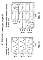
- FIG. 4 d shows M12/M11, M21/M11 and M33/M11 Mueller Matrix components obtained with no B Field applied.
- 4 e shows Mueller Matrix Elements M13/M11, M31/M11, M23/M11 and M32/M11 obtained by applying the present invention method with a B field applied, and wherein the data shown is the difference ( 6 ) between that obtained when the Magnet is placed with the North Pole facing one direction and then the other.
- FIG. 5 is included to indicate that it is optimum to provide VIS-MIR and FIR-THz sources that provide output which overlaps in the range of about 1.0 to 1.4 THz.
- FIG. 5 shows that a preferred embodiment of the system allows sample investigation in both the THz and IR ranges, (eg. from 300 GHz to about 1.4 THz, and from about 1.0 THz and higher frequency). Further, it is indicated that below about 1.4 THz a first ( 31 ) is used to provide the electromagnetic radiation, and above about 1.0 THz a second (S 2 ) Source is used to provide the electromagnetic radiation.
- FIG. 5 shows an overlap in the range of about 1.0 to about 1.4 THz, and that a described system preferably provides the same results, (eg.
- FIG. 5 should be viewed as demonstrating a concrete and tangible presentation of results which can be achieved by application of a described Invention.
- FIG. 6 demonstrates displaying data (DIS) provided by a Detector (DET), (DET in FIGS. 1 d and 1 e ), obtained by practice of described systems using machine readable media of a computer (CMP), as well as indicates the Computer (CMP) can control Ellipsometer/Polarimeter elements operation.
- DET Detector
- CMP computer
Landscapes
- Physics & Mathematics (AREA)
- General Physics & Mathematics (AREA)
- Chemical & Material Sciences (AREA)
- Health & Medical Sciences (AREA)
- Spectroscopy & Molecular Physics (AREA)
- General Health & Medical Sciences (AREA)
- Analytical Chemistry (AREA)
- Biochemistry (AREA)
- Life Sciences & Earth Sciences (AREA)
- Immunology (AREA)
- Pathology (AREA)
- Electrochemistry (AREA)
- Chemical Kinetics & Catalysis (AREA)
- Toxicology (AREA)
- Investigating Or Analysing Materials By Optical Means (AREA)
Abstract
Description
M OHE(∈oeh(B)).
Although this equation is in general not invertible analytically, it can be used to determine the magneto-optic dielectric tensor from experimental Mueller matrix data through non-linear model mathematical regression analysis. Dielectric tensors, Mueller matrix calculus, generalized ellipsometry including data acquisition, as well as data analysis are further addressed in this section.
Magneto-Optical Dielectric Tensors
∈(OHE)=∈B=0+∈B.
The magneto-optic permittivity of a material within a given sample described by ∈B may originate from the response of bound and unbound charge carriers subjected to the magnetic field and the action of the Lorentz force. The magneto-optic response of a sample subjected to the integrated MIR, FIR and THz (OHE) instrument, and which is addressed herein is represented by a generally anisotropic and nonreciprocal tensor. Thus, the corresponding magneto-optic contributions X+ and X− to the permittivity tensor χ=∈−I, (where I is the 3×3 identity matrix), originate from the interaction of right- and left-handed circularly polarized light with the sample, respectively. Without loss of generality, if the magnetic field B is pointing in vector direction indicated by P=∈0χE, it can be described by arranging the electric fields in their circularly polarized eigensystem Ee=(Ex+iEy, Ex−iEy, Ez)=(E+, E−, Ez) by Pe=∈0×eEe=∈0(χ+E+,χ−E−,0), where i=sqrt{−1} is the imaginary unit. Transforming Pe back into the laboratory system the change of the dielectric tensor induced by the magnetic field takes the form:
Note, under field inversion B is reversed into −B, the polarizabilities for left- and right-handed circularly polarized light interchange. ∈B is only diagonal if χ+=χ−, and otherwise non-diagonal with anti-symmetric off diagonal elements.
Classic Dielectric Tensors (Lorentz-Drude Model)
m{umlaut over (x)}+mγ{dot over (x)}+mω 0 2 x=qE+q({umlaut over (x)}×B), (4)
where: m, q, μ=qm−1γ−1, x and ωD represent the effective mass tensor, the electric charge, the mobility tensor, the spatial coordinate of the charge carrier and the Eigen-frequency of the un-damped system without external excitation and magnetic field, respectively. For a time harmonic electromagnetic plane wave with an electric field E→E exp(−iωt) with angular frequency ω, the time derivative of the spatial displacement of the charge carrier is {dot over (x)}=v exp(iωt), where v is the velocity of the charge carrier. With j=nqv Eq. 4 reads:
where n is the charge carrier density. With the Levi-Cevita-Symbol ∈ijk, (note, in the following-equation the Einstein notation is used, and the covariance tensor and contravariance is ignored since all coordinate systems are Cartesian, and the summation is only executed over pairs of lower indices), the conductivity tensor σ, the dielectric constant ∈0, and using E=σ−ij and
the dielectric tensor for charge carriers subject to the external magnetic field B can be expressed as:
Polar Lattice Vibrations, (Lorentz Oscillator)
Where ∈l/k for (k=(x,y,z,)) is given by:
Where ωLO,kj, γLO,kj, ωTO,kj, and γTO,kj denote the k(x,y,z) component of the frequency and the broadening values of the jth longitudinal optical (LO) and transverse optical (TO) phonon modes, respectively, while the index j runs over l modes. Further details can be found in Hofmann et al., Applied Physical Letters 88, 042105 (2006); Barker, Phys. Rev., 136, A1290 (1964); Berryman et al. Phys. Rev. 174, 791, (1968); Gervais et al., J. Phys. C 7, 2374, (1974); Hofmann et al., Phys. Rev. B, 66, 19504 1 (2002)1 and a discussion of the requirements to broadening parameters, such as Im(∈L/K) greater than or equal to 0.0 are found in Kasic et al., Phys. Rev. B 61,7365, (2000).
Free Charges Carriers (Extended Drude Model)
where
is the plasma frequency, and ∈D is permittivity function of the isotropic Drude dielectric function. The magneto-optic contribution to the dielectric tensor ∈B D for isotropic effective masses and conductivities can be expressed, using Eq. 3, through polarizability functions for right- and left-handed circularly polarized light:
where
is the isotropic cyclotron frequency.
Non-Classic Dielectric Tensors (Inter-Landau-Level Transitions)
The permittivity tensor ∈B LL describing the contribution of a series of inter-Landau-level transitions to the dielectric tensor can be approximated by a sum of Lorentz oscillators. The quantities χ± in Eq. (3) are then expressed by:
where Ak, ω0,k, and γk are amplitude, transition energy, and broadening parameter of the kth inter Landau-level transition, respectively, which in general depend on the magnetic field. The phase factor was introduced here to describe the experimentally observed line shapes of all Mueller matrix elements.
Where S(out) and S(in) denote the Stokes vectors of the electromagnetic plane wave before and after the change of the coordinate system, or an interaction with a sample, respectively. Note that all Mueller matrix elements of the GE data discussed in this paper, are normalized by the element M11, therefore Mij is less than or equal to and M11=1.
Mueller Matrix and (OHE) Data
only deviate from zero if p- to s-polarization mode conversion appears, while the matrix elements in the two on-diagonal-blocks:
mainly contain information about p- to s-polarization mode conversion, while the matrix elements in the two on-diagonal-blocks mainly contain information about p-s-polarization mode conserving processes. It is to be appreciated that p- to p-polarization mode conversion is defined as the transfer of energy from the p-polarized channel of an electromagnetic plane wave to the s-polarized channel, or vice versa. Polarization mode conversion can appear when the p-s-coordinate system is different for Sin and Sout, or, when a sample shows birefringence, for example. In particular, polarization mode conversion appears if the dielectric tensor of a sample possesses non-vanishing off-diagonal elements. Therefore, in Mueller matrix data from optically isotropic samples, ideally all off-diagonal-block elements vanish, while, for example, magneto-optic birefringence can cause non-zero off-diagonal-block elements in the Mueller matrix.
Here, we define (OHE) data as Mueller matrix data from an (OHE) experiment [Eq. 1] with magnetic field +/−B and the corresponding zero field dataset:
M OHE ± =M(∈B+0+∈±B) (13)
δM ± =M OHE ± −M 0 =ΔM(∈B=0,∈±B) (14)
where M0=M(∈Bω0) is the Mueller matrix of the zero field experiment, and ΔM(∈Bω0,∈±B) is the magnetic field induced change of the Mueller matrix. This form of presentation is in particular advantageous in case the magnetic field causes only small changes in the Mueller matrix, and provides improved sensitivity to magnetic field dependent model parameters during data analysis. Another form of presentation for derived (OHE) data is:
δM + ±δM − =ΔM(∈Bω0,∈+B)±ΔM(∈Bω0,∈−B), (15)
that can be used to inspect symmetry properties of magneto-optic Mueller matrix data, and can help to improve the sensitivity to magnetic field dependent model parameters during data analysis.
Mueller Matrix Data Acquisition (GE)
respectively. Execution of the matrix multiplication characteristic for the corresponding ellipsometer type shows that, due to the rotation of optical elements, the measured intensity at the detector is typically sinusoidal. Fourier analysis of the detector signal provides Fourier coefficients, which are used to determine the Mueller matrix of the sample.
Data Analysis
where S, K and σM
-
- Visual (eg. <8.7 microns);
- MIR; (eg. 0.7-30 microns);
- FIR; (eg. 30->350 microns); and
- THz (eg. (eg. >350-1000 microns).
The relevant literature is not absolutely consistent in said definitions however and differences in how various publications define said ranges should not be interpreted to be significant in disclosure of the present invention.
-
- a) providing an ellipsometer comprising:
- a source of a beam of electromagnetic radiation characterized by at least one wavelength in a selection from the group consisting of the:
- Visual;
- MIR;
- FIR; and
- THz ranges;
- a polarizer;
- a stage for supporting a sample, said stage comprising an adjustable surface that is capable of orienting a sample placed thereupon via adjustment of at least one selection from the group consisting of: stage tip, stage tilt and rotation thereof about an axis projecting substantially normal to said stage surface, to desired value(s);
- an analyzer; and
- a detector of relevant electromagnetic
- radiation wavelengths.
- Said method further comprises providing a source of a magnetic field.
Said method further comprises:
- a source of a beam of electromagnetic radiation characterized by at least one wavelength in a selection from the group consisting of the:
- b) placing a sample on said stage and adjusting said stage so that stage tip and/or stage tilt and/or rotation thereof about an axis projecting substantially normal to said stage surface are set to desired values, and so that the source of a magnetic field provides a magnetic field other than parallel thereto at said surface of said sample;
- c) while applying the source of a magnetic field to apply a selected magnitude magnetic field other than parallel thereto at the surface of said sample, causing said source of electromagnetic radiation to provide a beam of electromagnetic radiation of a desired wavelength which is caused to pass through said polarizer and assume a polarization state, interact with said sample, pass through said analyzer and enter said detector which detector produces sample characterizing data.
Said method then continues with: - d) from data accumulated by said detector with the system adjusted as described in steps b) and c), evaluating anisotropic values for at least a partial Jones or Mueller Matrix; and
- e) from said anisotropic values for said at least a partial Jones or Mueller Matrix determining at least one of the free charge carrier longitudinal and/or transversal effective masses, and/or concentration, and/or mobility and/or type.
- a) providing an ellipsometer comprising:
-
- a) providing an ellipsometer comprising:
- a source of a beam of electromagnetic radiation characterized by at least one wavelength in a selection from the group consisting of the:
- Visual;
- MIR;
- FIR; and
- THz ranges.
Said ellipsometer system further comprises:
- a source of a beam of electromagnetic radiation characterized by at least one wavelength in a selection from the group consisting of the:
- a polarizer;
- a stage for supporting a sample, said stage comprising an adjustable surface that is capable of orienting a surface of a sample placed thereupon via adjustment of at least one selection from the group consisting of: stage tip, stage tilt and rotation thereof about an axis projecting substantially normal to said stage surface, to desired value(s); and
- a detector of relevant electromagnetic radiation wavelengths;
and - further providing a source of a magnetic field.
Said method continues with: - b) placing a sample on said stage and adjusting said stage so that stage tip and/or stage tilt and/or rotation thereof about an axis projecting substantially normal to said stage surface are set to desired values, and so that the source of a magnetic field provides a magnetic field other than parallel thereto at said surface of said sample;
- c) while applying the source of a magnetic field to apply a selected magnitude magnetic field other than parallel thereto at the surface of said sample, causing said source of electromagnetic radiation to provide a beam of electromagnetic radiation comprising at least one wavelength of a substantially exact multiple of a an optical path length in said sample, and which beam is caused to pass through said polarizer and assume a polarization state, interact with said sample, pass through said analyzer and enter said detector, which detector produces sample characterizing data;
- d) from data accumulated by said detector with the system adjusted as described in steps b) and c), evaluating anisotropic values for at least a partial Jones or Mueller Matrix; and
- e) from said anisotropic values for said at least a partial Jones or Mueller Matrix determining at least one of the free charge carrier concentration and/or mobility by direct calculation rather than by a mathematical regression procedure.
- a) providing an ellipsometer comprising:
In use said stage for supporting a sample can provide that the magnetic casing plate and interface plate are offset from one another to provide a gap therebetween, which gap contributes to formation of a cavity effect wherein at least some electromagnetic radiation directed at said sample by said source of a beam thereof passes through said sample, reflects from said surface associated with said at least one magnet and re-enters said sample.
-
- a) providing an ellipsometer comprising:
- a source of a beam of electromagnetic radiation characterized by at least one wavelength selected from the group consisting of:
- Visual;
- MIR;
- FIR; and
- THz;
- ranges;
- a polarizer;
- a stage for supporting a sample;
- an analyzer; and
- a detector.
Said methodology continues with: - b) placing a sample on said stage and adjusting said stage so that stage tip and/or stage tilt and/or rotation thereof about an axis projecting substantially normal to said stage surface are set to desired values, and so that the source of a magnetic field provides a magnetic field other than parallel thereto at said surface of said sample, and/or adjusting the source of a magnetic field which is oriented to provide a magnetic field other than parallel thereto at said surface of said sample, to achieve a desired value of magnetic field at said sample surface,
- c) while applying the source of a magnetic field to provide a selected magnitude magnetic field other than parallel thereto at the surface of said sample, causing said source of electromagnetic radiation to provide a beam of electromagnetic radiation which is caused to pass through said polarizer and assume a polarization state, interact with said sample, pass through said analyzer and enter said detector, which detector produces sample characterizing data;
And said method further involves: - d) from data accumulated by said detector with the system adjusted as described in steps b) and c), evaluating anisotropic values for at least a partial Jones or Mueller Matrix; and
- e) from said values for said at least a partial Jones or Mueller Matrix determining at least one of the free charge carrier concentration and/or mobility.
-
- placing said sample on said stage for supporting a sample with the back side thereof in contact with said stage and obtaining a first set of data, then flipping said sample so that it's surface is in contact with said stage and obtaining a second set of data; and
- first placing the north pole of a permanent magnet near to the sample and obtaining a first set of data, and then placing a south pole of the same or another magnet so that it is near the sample and obtaining a second set of data,
which is followed by subtracting said second set of data from said first, or vice-versa, for each of the resulting M1, and at least one of said resulting M23 and M32 Mueller Matrix elements determined, and wherein each determined M23 and M32 is divided by the resulting M11, prior to using said resulting at least one of the resulting M23 and M32 values as data upon which to regress a model of said sample that includes free charge carrier longitudinal and transversal effective masses, concentration, mobility and type, thereby allowing their evaluation.
Said methodology and can further involve at least one of M13 and M31 also being determined by the same procedure of obtaining a first set of data with the sample back side in contact with said stage and then flipping said sample over so that it's surface is in contact with said stage and obtaining a second set of data; or by first placing the north pole of a permanent magnet near to the sample and obtaining a first set of data, and then placing a south pole of the same or another permanent magnet so that it is near the sample and obtaining a second set of data.
As before, the method continues with subtracting said second set of data from said first, or vice-versa, for each of the resulting M11, and at least one of said resulting M13 and M31 Mueller Matrix elements determined, prior to using said resulting at least one of M23 and M32 and at least one of M13 and M31 values as data upon which to simultaneously regress a model of said sample that includes free charge carrier longitudinal and transversal effective masses, concentration, mobility and type, thereby allowing their evaluation.
-
- placing said sample on said stage for supporting a sample with the back side thereof in contact with said stage and obtaining a first set of data, then flipping said sample so that it's surface is in contact with said stage and obtaining a second set of data; and
- by first placing the north pole of a permanent magnet near to the sample and obtaining a first set of data, and then placing the south pole of the same or another magnet so that it is near the sample and obtaining a second set of data. (Note, where a single permanent magnet is used this amounts to “flipping” it over. However, any approach to modulating the effective magnetic field “seen” by a sample between the obtaining of data sets is within the scope of the present invention. That is, specific examples given are not to be considered to be of a limiting nature as regards the actual motion practiced. Because it is convenient, a preferred approach might involve that a single magnet be literally “flipped” over to cause a change from a North to South pole being closer to a sample, or vice versa, is practiced between acquiring the identified two data sets. It is also possible though, to place two magnets on a slider, one with a North pole and one with a South pole oriented so that they can be made to face toward the sample in use. A lateral sliding motion of said slider then places one and then the other of said north and south poles nearer the sample between acquiring two different data sets. Any configuration which allows a modulation, (not even necessarily a complete pole type change), of a magnetic B Field near a sample is to be considered within the scope of possibilities as regards how to arrive at two data sets, (or modulate a signal).
Said methodology then involves subtracting said second set of data from said first, or vice-versa, for each of the resulting M11, and at least one of said resulting M23 and M32 Mueller Matrix elements determined, and wherein each determined M13 and M31 is divided by M11, prior to using said resulting at least one of M13 and M31 values as data upon which to regress a model of said sample that includes free charge carrier longitudinal and transversal effective masses, concentration, mobility and type, thereby allowing their evaluation.
Further, said methodology can involve at least one of M23 and M32 also being determined by the same procedure of data being determined by the same procedure of data being determined by obtaining a first set of data with the sample back side in contact with said stage and then flipping said sample over so that it's surface is in contact with said stage and obtaining a second set of data; or again by first placing the north pole of a permanent magnet near to the sample and obtaining a first set of data, and then flipping the magnet so that the south pole thereof is near the sample and obtaining a second set of data, and then subtracting said second set of data from said first for each of the resulting M11, and at least one of said resulting M23 and M32 Mueller Matrix elements determined, prior to using said resulting at least one of M23 and M32 and at least one of M23 and M32 values as data upon which to simultaneously regress a model of said sample that includes free charge carrier longitudinal and transversal effective masses, concentration, mobility and type, thereby allowing their evaluation.
-
- a) providing an ellipsometer comprising:
- a source of a beam of electromagnetic radiation characterized by at least one wavelength in a selection from the group consisting of the:
- Visual;
- MIR;
- FIR; and
- THz; ranges;
- a polarizer;
- a stage for supporting a sample;
- an analyzer; and
- a detector;
- a source of a beam of electromagnetic radiation characterized by at least one wavelength in a selection from the group consisting of the:
- and a source of a magnetic field having a surface associated therewith and which is oriented to provide a magnetic field other than parallel thereto at said surface of said sample.
As before, said method continues with: - b) placing a sample on said stage and adjusting said stage so that stage tip and/or stage tilt and/or rotation thereof about an axis projecting substantially normal to said stage surface are set to desired values, and so that the source of a magnetic field provides a magnetic field other than parallel thereto at said surface of said sample, and/or further adjusting the source of a magnetic field so that it is oriented to provide a magnetic field other than parallel thereto at said surface of said sample of a desired value;
- c) while applying the source of a magnetic field to apply a magnetic field other than parallel thereto at the surface of said sample or a desired value, causing said source of electromagnetic radiation to provide a beam of electromagnetic radiation comprising at least one wavelength of substantially an exact multiple of an optical path length in said sample, which beam is caused to pass through said polarizer and assume a polarization state, interact with said sample, pass through said analyzer and enter said detector, which detector produces sample characterizing data.
Said method then further involves: - d) from data accumulated by said detector with the system adjusted as described in steps b) and c), evaluating anisotropic values for at least a partial Jones or Mueller Matrix; and
- e) from said values for said at least a partial Jones or Mueller Matrix directly determining at least one of the free charge carrier concentration and/or mobility.
Said just recited methodology is, however, distinguished in that, while data is being accumulated by said detector, a gap is caused to exist between at least one selection from the group consisting of: - 1) said sample backside and the sample supporting stage; and
- 2) said sample supporting stage and said surface associated with said source of a magnetic field which is oriented to provide a magnetic field other than parallel thereto at said surface of said sample of a desired value;
such that a cavity is formed in which at least some electromagnetic radiation in the beam thereof directed at said sample by said source of a beam of electromagnetic radiation passes through said sample, and is coherently reflected back thereinto by said surface associated with said source of a magnetic field.
- a) providing an ellipsometer comprising:
Continuing, in use said polarization state generator is caused to direct a polarized beam of electromagnetic radiation to interact with a sample on said stage for supporting a sample, which after said interaction presents as a beam of electromagnetic radiation that enters said polarization state detector, that in response produces sample characterizing data.
And, said system as just recited can further comprise a mechanism that enables aligning the substantially flat surface of said stage and the substantially flat surface associated with said magnet so that they are substantially parallel to one another by a tip/tilt procedure. Said present invention provides that it can be said stage for supporting a sample that is caused to undergo said tip/tilt procedure to align the substantially flat surface associated with said magnet substantially parallel to the stage substantially flat surface, and/or it can be said substantially flat surface associated with said magnet that is caused to undergo said tip/tilt procedure to align the substantially flat surface associated with said magnet substantially parallel to the stage substantially flat surface.
-
- a backward wave-oscillator (BWO);
- an optional frequency multiplier (FM);
- an optional first concave parabolic mirror (PM1),
- an optional reflecting means (M1);
- a first rotatable wire grid polarizer (WGP1);
- an optional second concave parabolic mirror (PM2);
- a rotating wire grid polarizer (RWGP);
- a stage for (STG) supporting a sample (S);
- a rotating retarder (RRET) (comprising first, second, third and fourth elements as shown in
FIGS. 3c-3g ); saidFIG. 3c demonstrating a preferred arrangement of:- first (RP), second (RM1), third (RM2) and fourth (RM3) reflective elements from each of which, in use, an electromagnetic beam reflects once,
- said first reflective element (RP) being prism (RP) which receives a beam through a first side thereof and exits a reflected beam through a third side thereof,
- said reflection being from a second side thereof oriented at prism forming angles to said first and third sides; said elements (RP) (RM1) (RM2) (RM3) being oriented with respect to one another such that the locus of the beam reflecting from the second side of said prism approaches said second reflective side thereof at an angle equal to or greater than that required to achieve total internal reflection within said prism (RP),
- and such that the locus of beam reflected from the fourth element in the sequence of elements is substantially co-linear and without deviation or displacement from the locus of the beam received by the first element in said sequence of elements,
- an optional third concave parabolic mirror (PM3);
- a second rotatable wire grid polarizer (WGP2);
- an optional fourth concave parabolic mirror (PM4); and
- a Golay cell detector (DET).
-
- stage (STG) for supporting a sample (S);
- rotating retarder comprising first (RP), second (RM1), third (RM2) and fourth (RM3) elements;
- third concave parabolic mirror (PM3);
- second rotatable wire grid polarizer (WGP2);
- fourth concave parabolic mirror (PM4); and
- Golay cell detector (DET);
about a vertical axis centered at a midpoint of said stage (STG) for supporting a sample (S) such that the angle of incidence (6) at which said beam of terahertz frequency electromagnetic radiation approaching from said rotating wire grid polarizer (RWGP), and the angle of reflection (e) of said beam from said sample (S) placed on said stage (STG) for supporting a sample, can be adjusted.
-
- a) a mechanism for adjusting tip and/or tilt of a surface of a sample (S) placed on a surface of said stage (STG) for supporting a sample (S);
- b) an interface plate (IP) comprising said stage for supporting a sample, and which is controlled by said mechanism for adjusting the tip and/or tilt of a surface of a sample (S) placed thereon on a surface of said stage;
- c) a magnetic casing plate (MCP) comprising at least one magnet holder (MH1) (MH2) for securing at least one magnet thereto, said magnetic casing plate (MCP) and interface plate (IP) being off-settable from one another and controlled in relative orientation with respect to one another by, for instance, a motor, and wherein a selection form the group consisting of: one magnet holder (MH1); and two magnet holders (MH1) (MH2), which can be, but do not necessarily need to be so, interconnected by a magnetic material. (eg. Iron), support bar (ISB) as shown in
FIG. 2c , and in which the sample supporting stage (STG) can be adjusted to be at a desired distance from and in a desired orientation with respect to said magnet(s) (MAG1) (MAG2) in said holder(s) thereof (MH1) (MH2) by said mechanism for adjusting tip and/or tilt of a surface of a sample (S) placed on a surface of said stage (STG) for supporting a sample (S).
Claims (39)
Priority Applications (2)
| Application Number | Priority Date | Filing Date | Title |
|---|---|---|---|
| US14/545,816 US9851294B1 (en) | 2014-08-18 | 2015-06-24 | Integrated mid-infrared, far infrared and terahertz optical Hall effect (OHE) instrument, and method of use |
| US15/732,252 US10073120B1 (en) | 2014-08-18 | 2017-10-13 | Integrated vacuum-ultraviolet, mid and near-ultraviolet, visible, near, mid and far infrared and terahertz optical hall effect (OHE) instrument, and method of use |
Applications Claiming Priority (2)
| Application Number | Priority Date | Filing Date | Title |
|---|---|---|---|
| US201462070239P | 2014-08-18 | 2014-08-18 | |
| US14/545,816 US9851294B1 (en) | 2014-08-18 | 2015-06-24 | Integrated mid-infrared, far infrared and terahertz optical Hall effect (OHE) instrument, and method of use |
Related Child Applications (1)
| Application Number | Title | Priority Date | Filing Date |
|---|---|---|---|
| US15/732,252 Continuation-In-Part US10073120B1 (en) | 2014-08-18 | 2017-10-13 | Integrated vacuum-ultraviolet, mid and near-ultraviolet, visible, near, mid and far infrared and terahertz optical hall effect (OHE) instrument, and method of use |
Publications (1)
| Publication Number | Publication Date |
|---|---|
| US9851294B1 true US9851294B1 (en) | 2017-12-26 |
Family
ID=60674689
Family Applications (1)
| Application Number | Title | Priority Date | Filing Date |
|---|---|---|---|
| US14/545,816 Active 2035-12-01 US9851294B1 (en) | 2014-08-18 | 2015-06-24 | Integrated mid-infrared, far infrared and terahertz optical Hall effect (OHE) instrument, and method of use |
Country Status (1)
| Country | Link |
|---|---|
| US (1) | US9851294B1 (en) |
Cited By (5)
| Publication number | Priority date | Publication date | Assignee | Title |
|---|---|---|---|---|
| US20150100277A1 (en) * | 2013-10-04 | 2015-04-09 | Axometrics, Inc. | Method and apparatus for measuring parameters of optical anisotropy |
| CN110596011A (en) * | 2019-08-26 | 2019-12-20 | 华中科技大学 | Method for measuring dielectric tensor of material |
| CN112066895A (en) * | 2020-07-22 | 2020-12-11 | 北京量拓科技有限公司 | Sample stage and ellipsometer with same |
| CN115684027A (en) * | 2022-09-27 | 2023-02-03 | 中北大学 | Ultra-high-speed ellipsometric precision measurement device and method based on single-elastic optical modulation self-feedback |
| WO2024147138A1 (en) * | 2023-01-05 | 2024-07-11 | Yissum Research Development Company Of The Hebrew University Of Jerusalem Ltd. | System and method of contactless sensing of material properties in a sample |
Citations (3)
| Publication number | Priority date | Publication date | Assignee | Title |
|---|---|---|---|---|
| US6485703B1 (en) * | 1998-07-31 | 2002-11-26 | The Texas A&M University System | Compositions and methods for analyte detection |
| US6872522B1 (en) * | 1996-06-25 | 2005-03-29 | Michael Mecklenburg | Broad specificity affinity arrays: a qualitative approach to complex sample discrimination |
| US8859876B2 (en) * | 1998-05-15 | 2014-10-14 | Lester F. Ludwig | Multi-channel signal processing for multi-channel musical instruments |
-
2015
- 2015-06-24 US US14/545,816 patent/US9851294B1/en active Active
Patent Citations (4)
| Publication number | Priority date | Publication date | Assignee | Title |
|---|---|---|---|---|
| US6872522B1 (en) * | 1996-06-25 | 2005-03-29 | Michael Mecklenburg | Broad specificity affinity arrays: a qualitative approach to complex sample discrimination |
| US7662560B2 (en) * | 1996-06-25 | 2010-02-16 | Michael Mecklenburg | Broad specificity affinity arrays: a qualitative approach to complex sample discrimination |
| US8859876B2 (en) * | 1998-05-15 | 2014-10-14 | Lester F. Ludwig | Multi-channel signal processing for multi-channel musical instruments |
| US6485703B1 (en) * | 1998-07-31 | 2002-11-26 | The Texas A&M University System | Compositions and methods for analyte detection |
Non-Patent Citations (7)
Cited By (9)
| Publication number | Priority date | Publication date | Assignee | Title |
|---|---|---|---|---|
| US20150100277A1 (en) * | 2013-10-04 | 2015-04-09 | Axometrics, Inc. | Method and apparatus for measuring parameters of optical anisotropy |
| US9989454B2 (en) * | 2013-10-04 | 2018-06-05 | Axometrics, Inc. | Method and apparatus for measuring parameters of optical anisotropy |
| CN110596011A (en) * | 2019-08-26 | 2019-12-20 | 华中科技大学 | Method for measuring dielectric tensor of material |
| CN110596011B (en) * | 2019-08-26 | 2020-12-29 | 华中科技大学 | A kind of material dielectric tensor measurement method |
| WO2021036354A1 (en) * | 2019-08-26 | 2021-03-04 | 华中科技大学 | Method for measuring dielectric tensor of material |
| US11644413B2 (en) | 2019-08-26 | 2023-05-09 | Huazhong University Of Science And Technology | Method for measuring dielectric tensor of material |
| CN112066895A (en) * | 2020-07-22 | 2020-12-11 | 北京量拓科技有限公司 | Sample stage and ellipsometer with same |
| CN115684027A (en) * | 2022-09-27 | 2023-02-03 | 中北大学 | Ultra-high-speed ellipsometric precision measurement device and method based on single-elastic optical modulation self-feedback |
| WO2024147138A1 (en) * | 2023-01-05 | 2024-07-11 | Yissum Research Development Company Of The Hebrew University Of Jerusalem Ltd. | System and method of contactless sensing of material properties in a sample |
Similar Documents
| Publication | Publication Date | Title |
|---|---|---|
| Zhang et al. | Terahertz field-induced nonlinear coupling of two magnon modes in an antiferromagnet | |
| Hofmann et al. | Variable-wavelength frequency-domain terahertz ellipsometry | |
| US10073120B1 (en) | Integrated vacuum-ultraviolet, mid and near-ultraviolet, visible, near, mid and far infrared and terahertz optical hall effect (OHE) instrument, and method of use | |
| Fujiwara | Spectroscopic ellipsometry: principles and applications | |
| Mosley et al. | Terahertz spectroscopy of anisotropic materials using beams with rotatable polarization | |
| US9851294B1 (en) | Integrated mid-infrared, far infrared and terahertz optical Hall effect (OHE) instrument, and method of use | |
| Nagashima et al. | Polarization-sensitive THz-TDS and its application to anisotropy sensing | |
| Castro-Camus | Polarization-resolved terahertz time-domain spectroscopy | |
| Neshat et al. | Developments in THz range ellipsometry | |
| Arora et al. | Magneto-optical Kerr effect spectroscopy based study of Landé g-factor for holes in GaAs/AlGaAs single quantum wells under low magnetic fields | |
| Hofmann et al. | Terahertz ellipsometry and terahertz optical-Hall effect | |
| US20140284484A1 (en) | Terahertz ellipsometer system, and method of use | |
| Neugebauer et al. | Comparison of coherent phonon generation by electronic and ionic Raman scattering in LaAlO 3 | |
| Ueda et al. | Non-equilibrium dynamics of spin-lattice coupling | |
| Ohnoutek et al. | Strong interband Faraday rotation in 3D topological insulator Bi2Se3 | |
| EP2798322B1 (en) | Terahertz ellipsometer system, and method of use | |
| Boschini et al. | A flexible experimental setup for femtosecond time-resolved broad-band ellipsometry and magneto-optics | |
| Cobet | Ellipsometry: a survey of concept | |
| Nakajima et al. | Polarized and unpolarized neutron scattering for magnetic materials at the triple-axis spectrometer PONTA in JRR-3 | |
| Koleják et al. | Terahertz time-domain ellipsometry with spintronic emitters: Pauli coefficients as a superior alternative to Jones and Mueller matrices | |
| Knight et al. | Electromagnon excitation in cupric oxide measured by Fabry-Pérot enhanced terahertz Mueller matrix ellipsometry | |
| Pidgeon et al. | Infra-red faraday rotation in semiconductors: Double beam phase-sensitive method for the measurement of infra-red Faraday rotation, ellipticity and Voigt effect | |
| Cross et al. | Dual-modulator broadband infrared<? A3B2 show [pmg: line-break justify=" yes"/]?> Mueller matrix ellipsometry | |
| Glezer Moshe et al. | Modified Martin–Puplett interferometer for magneto-optical Kerr effect measurements at sub-THz frequencies | |
| Hofmann et al. | INTEGRATED MID-INFRARED, FAR INFRARED AND TERAHERTZ OPTICAL HALL EFFECT (OHE) INSTRUMENT, AND METHOD OF USE |
Legal Events
| Date | Code | Title | Description |
|---|---|---|---|
| AS | Assignment |
Owner name: UNIV. OF NEBRASKA BOARD OF REGENTS, NEBRASKA Free format text: ASSIGNMENT OF ASSIGNORS INTEREST;ASSIGNORS:HOFMANN, TINO;SCHUBERT, MATHIAS M.;SCHOECHE, STEFAN;AND OTHERS;REEL/FRAME:037045/0707 Effective date: 20150205 Owner name: J.A. WOOLLAM CO., INC., NEBRASKA Free format text: ASSIGNMENT OF ASSIGNORS INTEREST;ASSIGNORS:HERZINGER, CRAIG M.;WOOLLAM, JOHN A.;PRIBIL, GREG K.;AND OTHERS;REEL/FRAME:037045/0527 Effective date: 20150205 |
|
| STCF | Information on status: patent grant |
Free format text: PATENTED CASE |
|
| MAFP | Maintenance fee payment |
Free format text: PAYMENT OF MAINTENANCE FEE, 4TH YR, SMALL ENTITY (ORIGINAL EVENT CODE: M2551); ENTITY STATUS OF PATENT OWNER: SMALL ENTITY Year of fee payment: 4 |
|
| MAFP | Maintenance fee payment |
Free format text: PAYMENT OF MAINTENANCE FEE, 8TH YR, SMALL ENTITY (ORIGINAL EVENT CODE: M2552); ENTITY STATUS OF PATENT OWNER: SMALL ENTITY Year of fee payment: 8 |