US9850098B2 - Polygon compensation coupling system for chain and sprocket driven systems - Google Patents
Polygon compensation coupling system for chain and sprocket driven systems Download PDFInfo
- Publication number
- US9850098B2 US9850098B2 US14/774,759 US201314774759A US9850098B2 US 9850098 B2 US9850098 B2 US 9850098B2 US 201314774759 A US201314774759 A US 201314774759A US 9850098 B2 US9850098 B2 US 9850098B2
- Authority
- US
- United States
- Prior art keywords
- rotatable element
- compensation
- rotatable
- coupling system
- polygon
- Prior art date
- Legal status (The legal status is an assumption and is not a legal conclusion. Google has not performed a legal analysis and makes no representation as to the accuracy of the status listed.)
- Expired - Fee Related, expires
Links
Images


Classifications
-
- B—PERFORMING OPERATIONS; TRANSPORTING
- B66—HOISTING; LIFTING; HAULING
- B66B—ELEVATORS; ESCALATORS OR MOVING WALKWAYS
- B66B23/00—Component parts of escalators or moving walkways
- B66B23/02—Driving gear
- B66B23/022—Driving gear with polygon effect reduction means
-
- F—MECHANICAL ENGINEERING; LIGHTING; HEATING; WEAPONS; BLASTING
- F16—ENGINEERING ELEMENTS AND UNITS; GENERAL MEASURES FOR PRODUCING AND MAINTAINING EFFECTIVE FUNCTIONING OF MACHINES OR INSTALLATIONS; THERMAL INSULATION IN GENERAL
- F16H—GEARING
- F16H55/00—Elements with teeth or friction surfaces for conveying motion; Worms, pulleys or sheaves for gearing mechanisms
- F16H55/02—Toothed members; Worms
- F16H55/30—Chain-wheels
- F16H55/303—Chain-wheels for round linked chains, i.e. hoisting chains with identical links
-
- F—MECHANICAL ENGINEERING; LIGHTING; HEATING; WEAPONS; BLASTING
- F16—ENGINEERING ELEMENTS AND UNITS; GENERAL MEASURES FOR PRODUCING AND MAINTAINING EFFECTIVE FUNCTIONING OF MACHINES OR INSTALLATIONS; THERMAL INSULATION IN GENERAL
- F16H—GEARING
- F16H7/00—Gearings for conveying rotary motion by endless flexible members
- F16H7/06—Gearings for conveying rotary motion by endless flexible members with chains
Definitions
- the present disclosure generally relates to chain and sprocket driven systems and, more particularly, relates to reducing a polygon effect associated with chain and sprocket driven systems, such as passenger conveyor systems.
- passenger conveyor systems such as, escalators, moving walkways, moving sidewalks, etc. are widely used these days to effectively transport pedestrian traffic or other objects from one location to another. Areas of usage of these passenger conveyor systems often include airports, hotels, shopping malls, museums, railway stations and other public buildings.
- passenger conveyor systems typically have two landings (e.g., a top landing and a bottom landing in case of an escalator) and a plurality of steps/treads traveling in a closed loop in between the landings.
- the closed loop forms a load track and a return track interconnected by first and second turnaround sections located at the landings.
- Passenger conveyors also include moving handrails traveling together with the steps/treads and a truss structure supporting the treads/steps and moving handrails.
- the steps/treads are driven by a step chain (also called an escalator chain).
- the step chain is driven by a step chain sprocket and travels in a closed loop forming a load track and a return track interconnected by first and second turnaround sections.
- a drive module having a motor and a main shaft drives one or more main drive chain sprockets.
- the main drive chain sprockets in turn drive the step chain sprocket which is engaged by the step chain.
- the step chain engages the treads/steps for moving the treads/steps around the endless loop.
- a step chain like any other chain drive, includes a plurality of discrete chain links, called step chain links, connected together by way of connecting links, such as a pin and a link plate or a roller.
- a drive sprocket e.g., the step chain sprocket
- a drive sprocket includes a profiled wheel having a plurality of engaging teeth for meshing and engaging the connecting links (or possibly even engaging the step chain links) of the step chain, in order to move the step chain as the step chain sprocket rotates.
- the engagement of the connecting links of the step chain with the engaging teeth of the step chain sprocket causes the step chain to vibrate and fluctuate.
- vibrations and fluctuations are often called a polygon effect or a chordal action and not only affect the ride experience of a user (who typically feels these vibrations and fluctuations aboard the passenger conveyor system), but also cause undesirable friction between the step chain and the step chain sprocket, thereby reducing the service life time of those components.
- Noise generated by the vibrations resulting from the engagement of the step chain with the step chain sprocket is another concern.
- the intensity of polygon effect depends on the velocity of the step chain and the length of the chain links in relation to the diameter of the sprocket. The greater said relation and the higher the velocity of the step chain, the stronger the polygon effect.
- One possibility for reducing the polygon effect thus is to reduce the pitch of the step chain.
- one approach of mitigating the polygon effect involves increasing the number of step chain links in the step chain (which can reduce the step chain pitch), and/or correspondingly increasing the diameter of the step chain sprocket(s) to increase the number of teeth in engagement with the sprocket (which may also effectively reduce the step chain pitch).
- This techniques although effective in improving the riding experience of a user, nonetheless have several disadvantages.
- the overall cost of the associated system increases.
- the efforts involved with the necessary maintenance of the increased number of components increases, and so does the amount of lubricant needed to reduce the increased wear and tear amongst those components.
- This increased wear and tear can additionally reduce the service life time of the step chain and the step chain sprocket.
- the aforementioned approach does not address to the noise issue discussed above, and may in fact increase the noise due to a greater engagement of the step chain with the step chain sprocket.
- U.S. Pat. No. 6,351,096 B1 and WO 01/42122 A1 disclose electronic drive systems configured to control a motor driving the sprocket of a chain drive to rotate with non constant velocity, the non-constant rotation of the sprocket compensating the polygon effect. This solutions results in a fluctuation of the velocity of the motor requiring a repeated acceleration and deceleration of the motor and all connected moving elements.
- EP 1 479 640 B1 and U.S. Pat. No. 4,498,890 teach to compensate the polygon effect by providing a curved track section having a varying curvature in the straight portion of the chain next to the sprocket.
- Such curved track sections reduce the usable length of the chain loop, as the portion of the loop in which the curved section is located cannot not be used for transportation.
- WO 2012/161691 A1 discloses a polygon compensation coupling system for reducing a polygon effect in a chain driven system.
- the polygon compensation coupling system includes a chain sprocket and a main drive in engagement with the chain sprocket, such that the engagement defines a compensation curve to reduce the polygon effect.
- a polygon compensation coupling system comprises a first rotatable element, a second rotatable element and at least one linkage coupling the first rotatable element with the second rotatable element.
- the first and second rotatable elements may be arranged coaxially to each other.
- the linkage comprises at least one first coupling element pivotably coupled to the first rotatable element and at least one second coupling element pivotably coupled to the second rotatable element.
- the first and second coupling elements are pivotably coupled to each other at a hinge point, the hinge point being configured to move along a compensation curve varying the coupling between the first rotatable element and the second rotatable element.
- Exemplary embodiments of the invention further include a chain drive comprising at least one polygon compensation coupling system according to an exemplary embodiment of the invention, and a conveyor system, in particular a people conveyor as e.g. an escalator or a moving walkway, comprising such a chain drive.
- a chain drive comprising at least one polygon compensation coupling system according to an exemplary embodiment of the invention
- a conveyor system in particular a people conveyor as e.g. an escalator or a moving walkway, comprising such a chain drive.
- the polygon compensation coupling system provides a satisfying coupling between the drive, the sprocket and the chain, allowing to transfer large torques from a drive to the sprocket of a chain drive and at the same time compensate the polygon effect generated by the sprocket.
- a polygon compensation coupling system in the case of failure, will act as a simple coupling not including any compensating effect, thus enhancing safety.
- the input and output rotational elements may be arranged coaxially allowing an improved integration of the system.
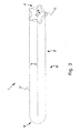
- FIG. 1 shows an example of a passenger conveyor system, in which a polygon compensation coupling system according to exemplary embodiments of the present invention may be used.
- FIG. 2 shows an example of a drive module to be used in combination with a passenger conveyor system as it is shown in FIG. 1 .
- FIG. 3 shows a schematic view of a chain drive for driving a conveyor system as it is shown in FIG. 1 .
- FIG. 4 shows a perspective view of a polygon compensation coupling system (PCC) according to a first exemplary embodiment of the invention.
- PCC polygon compensation coupling system
- FIG. 5 shows an example of a suitable compensation curve to be used in a PCC according to exemplary embodiments of the present invention.
- FIGS. 6 a to 6 c show front-side views of the PCC according to the first embodiment at three different points of time during operation.
- FIG. 7 shows a perspective view of a PCC according to a second exemplary embodiment of the invention.
- FIG. 8 a shows a perspective view of the first and second revolving elements and of the inner disk shaped element of PCC according to a second exemplary embodiment of the invention.
- FIG. 8 b shows a front-side view of the first and second revolving elements and of the inner disk shaped element of a PCC according to a second exemplary embodiment of the invention.
- FIGS. 9 a to 9 c show perspective views of a PCC according to a third embodiment of the invention in the assemble state and in partly assembled states, respectively.
- FIG. 10 a shows a sectional view of the PCC according to the third embodiment.
- FIG. 10 b shows an enlarged portion of FIG. 10 a.
- FIG. 11 shows the principal arrangement of the chain and the sprocket as a basis for calculating the compensation curve.
- FIG. 12 a shows the principal kinematic of a PCC of to the first embodiment.
- FIG. 12 b shows a geometrical scheme of a PCC of to the first embodiment.
- FIG. 13 is a plot showing the course of the angular distance ⁇ ( ⁇ ) between the first and second rotatable element in operation
- FIG. 1 An example of a passenger conveyor system 2 , in which exemplary embodiments of the present invention may be used, is shown in FIG. 1 .
- the passenger conveyor system 2 includes a bottom landing 18 connected to a top landing 20 via a plurality of steps (also referred to as treads) 4 and a truss 6 .
- a step chain 5 having a plurality of step chain links 22 is engaged with the plurality of treads 4 in order to drive and guide those treads 4 in an endless loop between the top landing 20 and the bottom landing 18 .
- the step chain 5 is driven by rotation of a step chain sprocket 12 , which is not visible in FIG. 1 .
- the passenger conveyor system 2 may further include a pair of moving handrails 24 , only one of which is shown in FIG. 1 .
- FIG. 2 shows an example of a drive module 50 to be used in a passenger conveyor system 2 as it is shown in FIG. 1 .
- the drive module 50 may be provided beneath the top landing 20 and may include a motor 52 , which may directly or indirectly drive a main drive shaft provided with a machine drive chain sprocket 54 .
- the machine drive chain sprocket 54 in turn may drive a main drive chain 56 to which is engaged a main drive chain (MDC) sprocket 57 .
- the main drive chain sprocket 57 may engage with, and rotate concurrently with, the step chain (STC) sprocket 12 which is configured to move the step chain 5 .
- the step chain (STC) sprocket 12 may be driven by the main drive shaft via a belt, cogged belt or via a gear train.
- the main drive shaft may directly drive (by way of belts, chains or gears) the MDC sprocket 57 , without the usage of the machine drive chain sprocket 44 and the main drive chain 56 .
- the main drive shaft may directly drive (by belts, chains or gears) the STC sprocket 12 without the usage of the machine drive chain sprocket 54 or the MDC sprocket 57 .
- FIG. 3 shows a schematic view of a chain drive 1 .
- the chain drive 1 may be used in a conveyor system 2 as it is shown in FIG. 1 .
- the chain drive 1 comprises a (step) chain 5 configured to rotate in a closed loop 16 forming a load track 7 and a return track 8 interconnected by first and second turnaround sections 9 , 10 , respectively.
- the turnaround sections 9 , 10 are located at opposing ends of the loop 6 .
- a step chain drive sprocket 12 which is configured for driving the chain 5 is arranged in the first turnaround section 9 shown on the right side of FIG. 3 .
- step chain drive sprocket 12 will turn clockwise in normal operation, as indicated by arrow R.
- chain 5 will travel from left to right in the upper load track 7 and from right to left in the lower return track 8 .
- the engagement of the step chain 5 with the step chain sprocket 12 takes place on the top of the step chain sprocket 12 in normal operation and at the lowest point of the step chain sprocket 12 when rotating in the opposite direction.
- a guiding trail may guide the step chain 5 towards the top point or bottom point of the step chain sprocket 12 , respectively. If this can not be realized due to system constraints, the velocity difference function and the compensation curve described below will have a different shape due to the different geometrical relations. The principle of polygon compensation, however, will remain the same.
- step chain drive sprocket 12 When the step chain drive sprocket 12 is driven with constant angular velocity, an undesirable polygon effect will occur due to the deflection of the chain 5 in the first and second turnaround sections 9 , 10 .
- a polygon compensation coupling system is arranged between the motor 52 and the step chain drive sprocket 12 , the PCC being configured to transform rotation of the motor 52 rotating with constant angular velocity, on the input side of the PCC, into rotation with non-constant angular velocity on the output side of the PCC. Transformation is effected such that the fluctuation of the speed of rotation of the step chain drive sprocket 12 will compensate the above mentioned polygon effect.
- FIG. 4 shows a perspective view of a polygon compensation coupling system (PCC) 30 according to a first exemplary embodiment of the invention.
- PCC polygon compensation coupling system
- the PCC 30 comprises a first rotatable element 31 , which is shown on the right side of FIG. 4 , coupled to a first shaft 37 extending to the right side and a second rotatable element 32 , which is shown on the left side of FIG. 4 , coupled to a second shaft 38 extending to the left side.
- the first and second rotatable elements 31 , 32 as well as the associated first and second shafts 37 , 38 are arranged coaxially to each other along a common center axis line A.
- the first and second shafts 37 , 38 are separate and connected to each other only by means of the rotatable elements 31 , 32 as will be explained in the following.
- the first and second rotatable elements 31 , 32 are formed as stars, respectively.
- Each of the first and second rotatable elements 31 , 32 comprises five spikes or protrusions 31 a , 32 a , which are formed equidistantly at predetermined intervals along the circumferential periphery of the rotatable elements 31 , 32 .
- the number of five protrusions 31 a , 32 a corresponds to the number of teeth of the step chain drive sprocket 12 .
- Coupling elements 34 a formed as levers are pivotably connected the protrusions 31 a , 32 a by means of connecting bolts 33 extending in axial direction, i.e. parallel to the center axis line A, through each of the protrusions 31 a , 32 a.
- Each of the coupling elements 34 a connected to one of the protrusions 31 a of the first rotatable element 31 is pivotably coupled to a corresponding coupling element, which is not visible in FIG. 4 , connected to a protrusion 32 a of the second rotatable element 32 by means of a joint comprising an axle 36 extending in axial direction trough the first and second coupling elements 34 a .
- the first rotatable element 31 is coupled with the second rotatable element 32 by means of the coupling elements 34 a , which are pivotably connected to each other by the axle 36 .
- At least one roller 35 is rotatably mounted to each of said axles 36 .
- a disk shaped stationary element 39 a which is not rotatable, is arranged coaxially to the first and second rotatable elements 31 , 32 in between said rotatable elements 31 , 32 along the axial direction.
- the outer periphery of the stationary element 39 a provides an inner race for the rollers 35 .
- An outer race for the rollers 35 is formed by the inner periphery of a stationary outer ring 39 b , which is not rotatable, as well, and which is arranged parallel to the stationary element 39 a in a radial distance therefrom providing a circumferential space between the disk shaped element 39 a and the outer ring 39 b accommodating the rollers 35 .
- the radial distance between the outer periphery of the stationary element 39 a and the inner periphery of the outer ring 39 b is set to be slightly larger than the diameter of the rollers 35 , therefore the rollers 35 will be in contact only with either the inner periphery of the stationary element 39 a , when the rotatable elements 31 , 32 rotate in a first direction or with the inner periphery of the outer ring 39 b , when the rotatable elements 31 , 32 rotate in a second, opposing direction.
- the link mechanism provided by the first and second coupling elements 34 a would couple the first and second rotatable elements 31 , 32 directly to each other so that they would rotate jointly with the same angular velocity when one of the shafts 37 , 38 is rotatably driven.
- the races formed by the peripheries of the stationary element 39 a and the outer ring 39 b are provided with a shape which deviates from a perfect circle and forms a compensation curve, as it is exemplary shown in FIG. 5 .
- the construction of the compensation curves forming the races will be described further below with reference to FIG. 11 .
- the radial distance from the center axis line A of the rollers 35 mounted to the axles 36 of the joints between the first and second coupling elements 34 a will change, when the first and second rotatable elements 31 , 32 are rotated by driving one of the shafts 37 , 38 and causing the rollers 35 to roll along one of the races formed by the peripheries of the stationary element 39 a and the outer ring 39 b .
- the distance in circumferential direction of two protrusions 31 a , 32 a of the first and second rotatable elements 31 , 32 coupled to each other by the coupling elements 34 a will fluctuate and a rotation of a (first) driving shaft 37 and the corresponding first rotatable element 31 with constant angular velocity will result in a rotation of the other (second) rotatable element 32 and the corresponding (second) driven shaft 38 , which is coupled to said other rotatable element 32 , with a non-constant, fluctuating angular velocity.
- Such construction allows to compensate for the polygon effect by forming the races provided by the peripheries of the stationary element 39 a and/or the outer ring 39 b according to a suitable compensation curve.
- FIGS. 6 a to 6 c show front-side views of the PCC 30 shown in FIG. 4 during operation at three different points of time, respectively.
- the outer ring 39 b is not shown in FIGS. 6 a to 6 c and only one link 34 a , 35 , 36 connecting the first and second rotatable elements 31 , 32 is shown.
- the first and second rotatable elements 31 , 32 are arranged so that the protrusions 32 a of the second rotatable element 32 are arranged parallel to the protrusions 31 a of the first rotatable element 31 and the protrusions 32 a of the second rotatable element 32 are covered by the protrusions 31 a of the first rotatable element 31 when viewed in axial direction, as it is shown in FIG. 6 a.
- FIG. 6 b the first rotatable element 31 shown in front has been rotated in clockwise direction, as indicated by arrow R, which caused the roller 35 to roll along the outer periphery of the stationary element 39 a .
- the roller 35 has moved slightly inwards in radial direction, straightening the joint formed by the first and second coupling elements 34 a , 34 b .
- This inward movement of the roller 35 has caused a lengthening of the link 34 a , 34 b , 35 , 36 formed by the first and second coupling elements 34 a , 34 b and the distance in circumferential direction between the protrusion 31 a of first rotatable element 31 and the corresponding protrusion 32 a of second rotatable element 32 has increased.
- the second rotatable element 32 has been rotated over a smaller angle than the first rotatable element 31 , i.e. the second rotatable element 32 has rotated with a smaller angular velocity than the first rotatable element 31 .
- FIG. 6 c the first rotatable element 31 shown in front has been rotated further in clockwise direction, as indicated by arrow R, which caused the roller 35 to roll further along the outer periphery of the stationary element 39 a . Due to the shape of the outer periphery of the stationary element 39 a , the roller 35 has moved slightly outwards in radial direction, bending the joint formed by the first and second coupling elements 34 a , 34 b .
- the protrusions 31 a , 32 a of the first and second rotatable elements 31 , 32 are again arranged parallel to each other, so that the protrusions 32 a of the second rotatable elements 32 are covered by the protrusions 31 a of the first rotatable elements 31 when viewed in axial direction from the front. I.e. in the time interval between FIGS. 6 a and 6 c the first and second rotatable elements 31 , 32 have been rotated by the same angle and with the same average angular velocity.
- the velocity of the second rotatable element 32 was lower in the first time interval from the time the PCC had the configuration shown in FIG. 6 a to the time the PCC had the configuration shown in FIG. 6 b .
- the velocity of the second rotatable element 32 was higher in the second time interval that passed between the PCC configurations shown in FIGS. 6 b and 6 c , respectively.
- FIG. 7 shows a perspective view of a polygon compensation coupling system (PCC) 40 according to a second exemplary embodiment of the invention.
- PCC polygon compensation coupling system
- the first and second rotatable elements 41 , 42 which are again rotatably arranged co-axially along a common center axis line A, are formed as disks, respectively.
- the planes of the disks are oriented parallel to each other and perpendicular to the center axis line A.
- a plurality of circular shaped pockets are formed in the plane of the disks of the first and second rotatable elements 41 , 42 , respectively.
- the pockets are arranged at positions which are equidistantly separated along the circumferential direction of the rotatable elements 41 , 42 .
- a circular shaped revolving element 44 a , 44 b is rotatably accommodated in each of said pockets.
- Each revolving element 44 a accommodated in one of the pockets of the first rotatable element 41 is connected by means of an interconnecting axle 46 to a corresponding revolving element 44 b (which is not visible in FIG. 7 ) accommodated in one of the pockets of the second rotatable element 42 .
- the interconnecting axle 46 is arranged eccentrically to each of the revolving elements 44 a , 44 b and provided with at least one roller 45 arranged between an inner disk shaped stationary element 49 a providing an inner race and a stationary outer ring 49 b providing an outer race for the rollers 45 .
- the radial distance between the stationary element 49 a and the outer ring 49 b is set to be slightly larger than the diameter of the rollers 45 , so that the rollers 45 will be in contact only with either the outer periphery of the stationary element 49 a , in case the rotatable elements 41 , 42 rotate in a first direction, or with the inner periphery of the outer ring 49 b , in case the rotatable elements 41 , 42 rotate in a second, opposing direction.
- the race defined by the stationary element 49 a and the outer ring 49 b is not exactly circular but has a shape which is similar to the shape exemplary shown in FIG. 5 .
- FIGS. 8 a and 8 b show the first and second revolving elements 44 a , 44 b eccentrically coupled by the interconnecting axle 46 , which is provided with a roller 45 , and the inner stationary element 49 a in a perspective view ( FIG. 8 a ) and in a front view ( FIG. 8 b ).
- the first and second rotatable elements 41 , 42 accommodating the revolving elements 44 a , 44 b as well as the outer ring 49 b are not shown in FIGS. 8 a and 8 b.
- first rotatable element 41 (not shown) is driven by an external source, e.g. a motor, providing input rotation, and that the second rotatable element 42 (not shown) delivers the output rotation of the PCC 40 .
- an external source e.g. a motor
- the revolving elements 44 a arranged in the pockets of the first rotatable element 41 travel circularly around the center axis line A of the PCC 40 and the rollers 45 provided on the interconnecting axles 46 travel along the outer periphery of the disk shaped stationary element 49 a .
- the outer periphery of the disk shaped stationary element 49 a would be formed exactly circular, the first and second rotatable elements 41 , 42 would rotate jointly with the same angular velocity.
- the first (input) rotatable element 31 , 41 is coupled to a driving motor 52 rotating with constant angular velocity
- the second (output) rotatable element 32 , 42 is connected to the step chain drive sprocket 12 of a chain drive 1 .
- FIGS. 9 a to 9 c show perspective views of a PCC 60 according to a third embodiment of the invention in an assembled state ( FIG. 9 a ) and in partly assembled states ( FIGS. 9 b , 9 c ).
- FIG. 10 a shows a sectional view of said PCC 60 according to the third embodiment and
- FIG. 10 b shows an enlarged portion B of FIG. 10 a.
- the PCC 60 according to the third embodiment employs the same principle as the PCC 40 according to the second embodiment, which has been discussed before, but comprises two driven rotatable elements 62 a , 62 b corresponding to the second rotatable element 42 of the second embodiment, the driving (first) rotatable 61 element being sandwiched between said two driven rotatable elements 62 a , 62 b.
- the rotatable elements 61 , 62 a , 62 b and the rollers 65 which correspond to the rollers 45 of the second embodiment, are arranged in a housing 75 comprising two parts 72 , 74 , the two parts 72 , 74 connected to each other in the assembled state by means of bolts 76 which are introduced in corresponding bolt holes 80 provided in the two parts 72 , 74 of the housing 75 .
- a five teeth step chain drive sprocket 12 is mounted to the driven shaft 68 , which is connected to the driven rotatable elements 62 a , 62 b , and a tooth belt wheel 70 is mounted to the driving shaft 67 connected to the driving rotatable element 61 .
- Two compensation races 72 a , 72 b , 74 a , 74 b are formed in each of the two parts 72 , 74 of the housing 75 .
- Five rollers 65 are rolling along each of said compensation races 72 a , 72 b , 74 a , 74 b .
- the compensation races 72 a , 72 b formed in the first part 72 are identical with the compensation races 74 a , 74 b formed in the second part 74 .
- embodiments are possible, in which the compensation races 72 a , 72 b formed in the first part 72 differ from the compensation races 74 a , 74 b formed in the second part 74 .
- the compensation races 72 a , 72 b 74 a , 74 b are designed with the radial distance between the inner races 72 a , 74 a and the outer races 74 a , 74 b being slightly larger than the diameter of the rollers 65 so that depending on the direction in which the PCC is turning the rollers 65 are in contact with either the inner races 72 a , 74 a or the outer races 74 a , 74 b.
- the driving shaft 67 forming the motor drive side of the PCC 60 carrying the tooth belt wheel 70 reaches to the middle of the PCC 60 and ends in a centered disc forming the driving rotatable element 61 .
- Five interconnecting axles 66 are mounted in a sliding bushing arrangement formed by revolving elements 64 a in the driving rotatable element 61 .
- the rollers 65 are mounted on the relevant eccentric portions on the outermost ends of these interconnecting axles 66 .
- driven second and third revolving elements 64 b mounted movably.
- the second and third revolving elements 64 b also have eccentric holes provided with sliding bearings.
- These revolving elements 64 b are rotatable mounted in the driven second and third rotatable elements 62 a , 62 b , which drive the driven shaft 68 carrying and supporting the sprocket 12 .
- the driving shaft 67 and the driven shaft 68 are arranged coaxially and are supported by the according housing parts 72 , 74 by means of roller bearings 84 , respectively.
- the two shafts 67 , 68 are coaxially mounted into each other with a sliding bearing 82 provided on their matching inner ends. This structure connects the two shafts 67 , 68 axially but keeps them rotatable with respect to each other.
- the assembled housing 75 is sealed by means of O-rings 78 and filled with gear oil providing lubrication of the relevant moveable parts.
- a PCC 60 according to the third embodiment almost all the available space is used for functional parts and the only free space is located between the rollers 65 in the compensation groove along the compensation races 72 a , 72 b 74 a , 74 b providing a robust and compact PCC 60 .
- compensation curve as it is exemplary shown in FIG. 5 will be explained below with reference to FIGS. 11, 12 a and 12 b .
- Such compensation curve may be used in any of the embodiments described herein.
- the compensation curve is to be designed such as to generate a fluctuating angular velocity ⁇ R ( ⁇ ) that results in the chain 5 traveling along the load/passenger track 7 with constant velocity v 0 .
- Said compensation curve has the same function as a curved compensation track 90 placed in a straight track segment of the chain drive, as it is known in the prior art e.g. from EP 1 479 640 B1 or U.S. Pat. No. 4,498,890.
- FIG. 12 a shows a simplified model of a PCC 30 according to the first embodiment in which each of the rotatable elements 31 , 32 comprises only three protrusions 31 a , 32 a .
- the second rotatable element 32 is connected to the step chain sprocket 12 (not shown).
- Turnable eccentrics or links 34 a , 34 b with respective lengths e 1 , e 2 are mounted to each of the rotatable elements 31 , 32 .
- the links 34 a , 34 b are connected to each other at a roller 35 .
- the rollers 35 travel along a stationary (not moving) compensation curve which is formed by the inner periphery of an outer ring 39 b and designed so that the distance b( ⁇ ) from the common center axis A of the rotatable elements 31 , 32 fluctuates with the angle of rotation ⁇ and therefore also the angle between the rotatable elements 31 , 32 changes, as it has been described in detail with reference to FIGS. 6 a to 6 c.
- the design of the compensation curve has to ensure that at a certain constant angular velocity ⁇ A of the first rotatable element 31 results in the non constant angular velocity angular velocity ⁇ ( ⁇ ) of the second rotatable element 32 , as it has been calculated before.
- This compensation effect reiterates with every tooth of the sprocket 12 .
- the compensation curve has to consist of n adjacent identical curve segments, with n being the number of teeth of the chain sprocket 12 . From this it is obvious that the maximum number of rollers 35 , which can travel along the compensation curve, is limited to n and therefore the minimum angular distance between two adjacent rollers 35 is 2 ⁇ /n.
- each of the straight lines f 1 and f 2 encloses with the angles ⁇ 1 and ⁇ 2 line b connecting the position of the roller 25 with the common center axis A.
- an analytic expression for ⁇ ( ⁇ ) known, it is possible to derive an analytic parametric representation of the PCC compensation curve as it is shown in FIG. 5 .
- the PCC 30 , 40 , 60 only compensates the polygon effect which is generated by the step chain drive sprocket 12 of the chain drive 1 .
- An additional polygon effect occurs due to the turning of the chain 5 in the second turnaround portion 10 of the chain drive 1 (see FIG. 3 ).
- At least one compensation curve may be placed in the return track 8 of loop 16 , in order to compensate the additional polygon effect cause by the second turnaround portion 10 .
- Using a PCC 30 , 40 , 60 eliminates the need of using a compensation curve in the load track 7 and thus allows to increase the usable length of the chain drive 1 without increasing its total length.
- chain driven systems in particular chain driven conveyors such as escalators or moving walkways may be built up, which need only little space in addition to the length of transportation.
- the cost for installing the conveyor may be reduced.
- This kind of conveyor is in particular beneficial if the available space is restricted.
- Particular embodiments of a polygon compensation system may include any of the following features, alone or in combination, with each other, unless otherwise noted:
- the compensation curve may be stationary.
- a stationary compensation curve allows for a stable structure of the PCC and a constant and exact alignment of the compensation curve which provides exact compensation over a long time of operation.
- the linkage may comprise at least one roller arranged at the hinge point, the roller being configured to roll along the compensation curve.
- a roller rolling along the compensation curve reduces the friction and wear resulting from the movement of the hinge point along the compensation curve. It thereby increases the efficiency and the lifetime of the PCC.
- At least one of the first and the second coupling elements may comprise a lever pivotably connected to the corresponding rotatable element. Levers connected to the rotatable elements provide reliable coupling elements.
- the first and the second coupling element may comprise a lever which is pivotably connected to the corresponding rotatable element.
- a symmetric structure of the PCC facilitates the assembly of the PCC and reduces the number of different elements needed.
- At least one of the first and second rotatable elements may comprise a plurality of radially extending protrusions, at least one of the first and second coupling elements being pivotably coupled to at least one of the protrusions.
- Radially extending protrusions provide well suited mounting points for the coupling elements and reduce the material used for the rotatable elements. The use of less material reduces the weight and the inertia of the rotatable elements, which facilitates the acceleration and deceleration of the rotatable elements.
- At least one of the first and second coupling elements may comprise at least one revolving element eccentrically coupled to the hinge point.
- Using eccentrically coupled revolving elements as coupling elements allows to increase the maximum torque which may be transferred by the PCC.
- At least one of the revolving elements may be rotatably accommodated within the first rotatable element or the second revolving element. Accommodating the revolving element(s) in the rotatable element(s) allows to increase the maximum torque which may be transferred by the PCC as the transfer of torque between the revolving element(s) in the rotatable element(s) is improved.
- the first and the second coupling elements both may comprise at least one revolving element eccentrically coupled to the hinge point.
- a symmetric structure of the PCC facilitates the assembly of the PCC and reduces the number of different elements needed.
- a plurality of revolving elements may be coupled to at least one of the rotatable elements. Increasing the number of revolving elements coupled to each of the rotatable elements allows to increase the maximum torque which may be transferred by the PCC, as the transfer of torque is distributed over a plurality of revolving elements.
- the axis of rotation of the at least one revolving element may be parallel to the axis of rotation of the respective rotatable element and/or the axis of rotation of the at least one revolving element of the first rotatable element may be arranged parallel to the axis of rotation of the at least one revolving element of the second rotatable element.
- a parallel arrangement of the axes allows a compact and stable structure of the PCC.
- the PCC additionally may comprise at least one third rotatable element and the linkage may comprise a first linkage and a second linkage, the first linkage coupling the first rotatable element with the second rotatable element and the second linkage coupling the first rotatable element with the third rotatable element.
- the linkage may comprise a first linkage and a second linkage, the first linkage coupling the first rotatable element with the second rotatable element and the second linkage coupling the first rotatable element with the third rotatable element.
- Embodiments of the PCC comprising two linkages, further may comprise two compensation curves, one compensation curve assigned to each linkage. Providing a separate compensation curve for each linkage simplifies the structure of the PCC.
- the first compensation curve may have the same or a different shape as the second compensation curve. Providing both compensation curves with the same shape facilitates the structure, manufacture and assembly of the PCC. Providing two different compensation curves provides more flexibility for compensation.
- the first rotatable element may be sandwiched between the second and the third rotatable elements, thus allowing a very compact structure of the PCC.
- the second rotatable element and the third rotatable element may be rigidly connected to each other in order to rotate jointly reducing the degrees of freedom in the PCC and providing a very stable structure.
- the compensation curve may be formed so that the second rotatable element rotates with non-constant angular velocity when the first rotatable element rotates with constant angular velocity in order to compensate for the polygon effect which occurs when the second rotatable element drives a step chain drive sprocket being part of a chain drive.
- the first rotatable element may be connected to at least one drive which is configured to rotate the first rotatable element.
- the second rotatable element may be connected to at least one sprocket for driving a chain drive providing a chain drive comprising polygon compensation.
Landscapes
- Engineering & Computer Science (AREA)
- General Engineering & Computer Science (AREA)
- Mechanical Engineering (AREA)
- Devices For Conveying Motion By Means Of Endless Flexible Members (AREA)
- Escalators And Moving Walkways (AREA)
Abstract
Description
Claims (23)
Applications Claiming Priority (1)
| Application Number | Priority Date | Filing Date | Title |
|---|---|---|---|
| PCT/IB2013/052091 WO2014140696A1 (en) | 2013-03-15 | 2013-03-15 | Polygon compensation coupling system for chain and sprocket driven systems |
Publications (2)
| Publication Number | Publication Date |
|---|---|
| US20160031678A1 US20160031678A1 (en) | 2016-02-04 |
| US9850098B2 true US9850098B2 (en) | 2017-12-26 |
Family
ID=51535937
Family Applications (1)
| Application Number | Title | Priority Date | Filing Date |
|---|---|---|---|
| US14/774,759 Expired - Fee Related US9850098B2 (en) | 2013-03-15 | 2013-03-15 | Polygon compensation coupling system for chain and sprocket driven systems |
Country Status (4)
| Country | Link |
|---|---|
| US (1) | US9850098B2 (en) |
| EP (1) | EP2969878B1 (en) |
| CN (1) | CN105452145B (en) |
| WO (1) | WO2014140696A1 (en) |
Families Citing this family (4)
| Publication number | Priority date | Publication date | Assignee | Title |
|---|---|---|---|---|
| WO2016086964A1 (en) | 2014-12-02 | 2016-06-09 | Otis Elevator Company | Drive chain and drive chain mechanism and conveyor comprising such a drive chain mechanism |
| CN108438754B (en) * | 2018-04-20 | 2019-12-10 | 苏州市相城区黄桥工业园经济发展有限公司 | Method for eliminating regular polygon chain vibration in chain conveyor |
| CN108438755B (en) * | 2018-04-24 | 2019-12-06 | 苏州市相城区黄桥工业园经济发展有限公司 | Method for eliminating regular polygon chain vibration in chain conveyor |
| US10625985B1 (en) * | 2019-01-25 | 2020-04-21 | Kone Corporation | Pedestrian conveyor mass damper to reduce step vibration |
Citations (8)
| Publication number | Priority date | Publication date | Assignee | Title |
|---|---|---|---|---|
| US3149715A (en) * | 1963-08-15 | 1964-09-22 | John P Massimiani | Conveyor safety device |
| US3155227A (en) * | 1960-10-19 | 1964-11-03 | Dominion Malting Ontario Ltd | Stabilizing means for endless conveyors |
| JP2002114472A (en) | 2000-10-04 | 2002-04-16 | Hitachi Ltd | Passenger conveyor and driving device |
| US20020142873A1 (en) * | 2001-01-26 | 2002-10-03 | Jorg Oser | Chain drive arrangement |
| US20050130780A1 (en) | 2002-05-03 | 2005-06-16 | Theodorus Henricus Johannes Carolina Korse | Chain transmission and chain |
| US20100255944A1 (en) | 2007-11-16 | 2010-10-07 | Ketten-Wulf Betriebs-Gmbh | Drive means and chain drive |
| WO2012161691A1 (en) | 2011-05-23 | 2012-11-29 | Otis Elevator Company | Polygon compensation coupling for chain and sprocket driven systems |
| US9718646B2 (en) * | 2013-04-08 | 2017-08-01 | Otis Elevator Company | Chain drive system with polygon compensation |
Family Cites Families (8)
| Publication number | Priority date | Publication date | Assignee | Title |
|---|---|---|---|---|
| DE443192C (en) * | 1926-05-09 | 1927-04-22 | Otto Johannes Koehler | Drive device for long-link conveyor chains |
| US4498890A (en) | 1982-12-20 | 1985-02-12 | General Electric Company | Fixed track chain drive |
| US6351096B1 (en) | 1999-04-30 | 2002-02-26 | Otis Elevator Company | Operation control apparatus for escalator |
| DE19958709C2 (en) | 1999-12-06 | 2001-10-25 | Kone Corp | Method and device for reducing the polygon effect in the deflection area of passenger conveyor systems |
| EP1440255B9 (en) | 2001-10-26 | 2011-04-20 | Ketten-Wulf Betriebs-GmbH | Link chain drive, as well as method to drive the drive chainwheel of a link chain |
| JP4107852B2 (en) | 2002-02-28 | 2008-06-25 | 東芝エレベータ株式会社 | Conveyor device |
| DE10218373A1 (en) * | 2002-04-25 | 2003-11-13 | Kone Corp | Drive system for moving staircases and pavements has a drive motor and a gearing mechanism to use a step/pallet chain/handrail drive shaft for an effective link with deflection elements/handrails. |
| CN101348208A (en) * | 2008-08-28 | 2009-01-21 | 西子奥的斯电梯有限公司 | Escalator non-circular chain sprocket driving device |
-
2013
- 2013-03-15 CN CN201380076659.9A patent/CN105452145B/en not_active Expired - Fee Related
- 2013-03-15 WO PCT/IB2013/052091 patent/WO2014140696A1/en not_active Ceased
- 2013-03-15 EP EP13877692.7A patent/EP2969878B1/en active Active
- 2013-03-15 US US14/774,759 patent/US9850098B2/en not_active Expired - Fee Related
Patent Citations (10)
| Publication number | Priority date | Publication date | Assignee | Title |
|---|---|---|---|---|
| US3155227A (en) * | 1960-10-19 | 1964-11-03 | Dominion Malting Ontario Ltd | Stabilizing means for endless conveyors |
| US3149715A (en) * | 1963-08-15 | 1964-09-22 | John P Massimiani | Conveyor safety device |
| JP2002114472A (en) | 2000-10-04 | 2002-04-16 | Hitachi Ltd | Passenger conveyor and driving device |
| US20020142873A1 (en) * | 2001-01-26 | 2002-10-03 | Jorg Oser | Chain drive arrangement |
| US20050130780A1 (en) | 2002-05-03 | 2005-06-16 | Theodorus Henricus Johannes Carolina Korse | Chain transmission and chain |
| US20100255944A1 (en) | 2007-11-16 | 2010-10-07 | Ketten-Wulf Betriebs-Gmbh | Drive means and chain drive |
| US8617014B2 (en) * | 2007-11-16 | 2013-12-31 | Ketten-Wulf Betriebs-Gmbh | Drive means and chain drive with polygonal compensation |
| WO2012161691A1 (en) | 2011-05-23 | 2012-11-29 | Otis Elevator Company | Polygon compensation coupling for chain and sprocket driven systems |
| US9599201B2 (en) * | 2011-05-23 | 2017-03-21 | Otis Elevator Company | Polygon compensation coupling for chain and sprocket driven systems |
| US9718646B2 (en) * | 2013-04-08 | 2017-08-01 | Otis Elevator Company | Chain drive system with polygon compensation |
Non-Patent Citations (1)
| Title |
|---|
| International Search Report or Written Opinion for application PCT/IB2013/052091 dated Dec. 17, 2013, 11 pages. |
Also Published As
| Publication number | Publication date |
|---|---|
| CN105452145B (en) | 2017-08-29 |
| CN105452145A (en) | 2016-03-30 |
| EP2969878B1 (en) | 2024-02-28 |
| WO2014140696A1 (en) | 2014-09-18 |
| EP2969878A1 (en) | 2016-01-20 |
| US20160031678A1 (en) | 2016-02-04 |
| EP2969878A4 (en) | 2017-03-29 |
Similar Documents
| Publication | Publication Date | Title |
|---|---|---|
| US10647548B2 (en) | Polygon compensation coupling for chain and sprocket driven systems | |
| EP1174382B1 (en) | Conveyor device | |
| US10214389B2 (en) | Drive chain and drive chain mechanism and conveyor comprising such a drive chain mechanism | |
| CN101868652B (en) | Drive means and chain drive | |
| AU2013354203B2 (en) | Conveying chain sprocket and/or deflection chain sprocket having an increased service life | |
| US9850098B2 (en) | Polygon compensation coupling system for chain and sprocket driven systems | |
| JP4191143B2 (en) | Passenger conveyor drive machine | |
| CN106458525A (en) | Link chain of a moving walkway or an escalator | |
| CN107580584A (en) | The pedal unit for personnel's conveyer including cantilever | |
| US10214390B2 (en) | Passenger conveyor | |
| CN101746661A (en) | Passenger delivery device | |
| CN107352376B (en) | Passenger conveyor | |
| WO2011095213A1 (en) | Escalator or moving sidewalk and pallet therefore | |
| US7665594B2 (en) | Passenger conveyor | |
| HK1194720A (en) | Polygon compensation coupling for chain and sprocket driven systems | |
| HK1213539B (en) | An escalator having a step band or to a moving walkway having a pallet band | |
| Dmello | CHAIN DRIVE IN TWO WHEELERS | |
| CN107191544A (en) | Chain gear transmission Anti-side-turning device and its chain wheel driving mechanism | |
| HK1229310A1 (en) | Link chain of a moving walkway or an escalator |
Legal Events
| Date | Code | Title | Description |
|---|---|---|---|
| AS | Assignment |
Owner name: OTIS GESELLSCAFT M.B.H., AUSTRIA Free format text: ASSIGNMENT OF ASSIGNORS INTEREST;ASSIGNORS:SRB-GAFFRON, WALTER;TUREK, ALEXANDER;SCHEDL, PHILLIP;SIGNING DATES FROM 20140701 TO 20140901;REEL/FRAME:036748/0742 Owner name: OTIS ELEVATOR COMPANY, CONNECTICUT Free format text: ASSIGNMENT OF ASSIGNORS INTEREST;ASSIGNOR:OTIS GESELLSCAFT M.B.H.;REEL/FRAME:036809/0269 Effective date: 20151007 |
|
| STCF | Information on status: patent grant |
Free format text: PATENTED CASE |
|
| MAFP | Maintenance fee payment |
Free format text: PAYMENT OF MAINTENANCE FEE, 4TH YEAR, LARGE ENTITY (ORIGINAL EVENT CODE: M1551); ENTITY STATUS OF PATENT OWNER: LARGE ENTITY Year of fee payment: 4 |
|
| FEPP | Fee payment procedure |
Free format text: MAINTENANCE FEE REMINDER MAILED (ORIGINAL EVENT CODE: REM.); ENTITY STATUS OF PATENT OWNER: LARGE ENTITY |
|
| LAPS | Lapse for failure to pay maintenance fees |
Free format text: PATENT EXPIRED FOR FAILURE TO PAY MAINTENANCE FEES (ORIGINAL EVENT CODE: EXP.); ENTITY STATUS OF PATENT OWNER: LARGE ENTITY |
|
| STCH | Information on status: patent discontinuation |
Free format text: PATENT EXPIRED DUE TO NONPAYMENT OF MAINTENANCE FEES UNDER 37 CFR 1.362 |
|
| FP | Lapsed due to failure to pay maintenance fee |
Effective date: 20251226 |