US9849538B2 - Watertight welding methods and components - Google Patents
Watertight welding methods and components Download PDFInfo
- Publication number
- US9849538B2 US9849538B2 US14/583,084 US201414583084A US9849538B2 US 9849538 B2 US9849538 B2 US 9849538B2 US 201414583084 A US201414583084 A US 201414583084A US 9849538 B2 US9849538 B2 US 9849538B2
- Authority
- US
- United States
- Prior art keywords
- groove
- tenon
- component portion
- ridge
- bonding material
- Prior art date
- Legal status (The legal status is an assumption and is not a legal conclusion. Google has not performed a legal analysis and makes no representation as to the accuracy of the status listed.)
- Active, expires
Links
Images


Classifications
-
- B—PERFORMING OPERATIONS; TRANSPORTING
- B23—MACHINE TOOLS; METAL-WORKING NOT OTHERWISE PROVIDED FOR
- B23K—SOLDERING OR UNSOLDERING; WELDING; CLADDING OR PLATING BY SOLDERING OR WELDING; CUTTING BY APPLYING HEAT LOCALLY, e.g. FLAME CUTTING; WORKING BY LASER BEAM
- B23K11/00—Resistance welding; Severing by resistance heating
-
- B—PERFORMING OPERATIONS; TRANSPORTING
- B23—MACHINE TOOLS; METAL-WORKING NOT OTHERWISE PROVIDED FOR
- B23K—SOLDERING OR UNSOLDERING; WELDING; CLADDING OR PLATING BY SOLDERING OR WELDING; CUTTING BY APPLYING HEAT LOCALLY, e.g. FLAME CUTTING; WORKING BY LASER BEAM
- B23K1/00—Soldering, e.g. brazing, or unsoldering
- B23K1/0008—Soldering, e.g. brazing, or unsoldering specially adapted for particular articles or work
-
- B—PERFORMING OPERATIONS; TRANSPORTING
- B23—MACHINE TOOLS; METAL-WORKING NOT OTHERWISE PROVIDED FOR
- B23K—SOLDERING OR UNSOLDERING; WELDING; CLADDING OR PLATING BY SOLDERING OR WELDING; CUTTING BY APPLYING HEAT LOCALLY, e.g. FLAME CUTTING; WORKING BY LASER BEAM
- B23K11/00—Resistance welding; Severing by resistance heating
- B23K11/08—Seam welding not restricted to one of the preceding subgroups
-
- B—PERFORMING OPERATIONS; TRANSPORTING
- B23—MACHINE TOOLS; METAL-WORKING NOT OTHERWISE PROVIDED FOR
- B23K—SOLDERING OR UNSOLDERING; WELDING; CLADDING OR PLATING BY SOLDERING OR WELDING; CUTTING BY APPLYING HEAT LOCALLY, e.g. FLAME CUTTING; WORKING BY LASER BEAM
- B23K20/00—Non-electric welding by applying impact or other pressure, with or without the application of heat, e.g. cladding or plating
- B23K20/10—Non-electric welding by applying impact or other pressure, with or without the application of heat, e.g. cladding or plating making use of vibrations, e.g. ultrasonic welding
-
- B—PERFORMING OPERATIONS; TRANSPORTING
- B23—MACHINE TOOLS; METAL-WORKING NOT OTHERWISE PROVIDED FOR
- B23K—SOLDERING OR UNSOLDERING; WELDING; CLADDING OR PLATING BY SOLDERING OR WELDING; CUTTING BY APPLYING HEAT LOCALLY, e.g. FLAME CUTTING; WORKING BY LASER BEAM
- B23K26/00—Working by laser beam, e.g. welding, cutting or boring
- B23K26/20—Bonding
- B23K26/206—Laser sealing
-
- B—PERFORMING OPERATIONS; TRANSPORTING
- B23—MACHINE TOOLS; METAL-WORKING NOT OTHERWISE PROVIDED FOR
- B23K—SOLDERING OR UNSOLDERING; WELDING; CLADDING OR PLATING BY SOLDERING OR WELDING; CUTTING BY APPLYING HEAT LOCALLY, e.g. FLAME CUTTING; WORKING BY LASER BEAM
- B23K33/00—Specially-profiled edge portions of workpieces for making soldering or welding connections; Filling the seams formed thereby
- B23K33/004—Filling of continuous seams
-
- B—PERFORMING OPERATIONS; TRANSPORTING
- B29—WORKING OF PLASTICS; WORKING OF SUBSTANCES IN A PLASTIC STATE IN GENERAL
- B29C—SHAPING OR JOINING OF PLASTICS; SHAPING OF MATERIAL IN A PLASTIC STATE, NOT OTHERWISE PROVIDED FOR; AFTER-TREATMENT OF THE SHAPED PRODUCTS, e.g. REPAIRING
- B29C65/00—Joining or sealing of preformed parts, e.g. welding of plastics materials; Apparatus therefor
- B29C65/02—Joining or sealing of preformed parts, e.g. welding of plastics materials; Apparatus therefor by heating, with or without pressure
- B29C65/08—Joining or sealing of preformed parts, e.g. welding of plastics materials; Apparatus therefor by heating, with or without pressure using ultrasonic vibrations
-
- B—PERFORMING OPERATIONS; TRANSPORTING
- B29—WORKING OF PLASTICS; WORKING OF SUBSTANCES IN A PLASTIC STATE IN GENERAL
- B29C—SHAPING OR JOINING OF PLASTICS; SHAPING OF MATERIAL IN A PLASTIC STATE, NOT OTHERWISE PROVIDED FOR; AFTER-TREATMENT OF THE SHAPED PRODUCTS, e.g. REPAIRING
- B29C65/00—Joining or sealing of preformed parts, e.g. welding of plastics materials; Apparatus therefor
- B29C65/78—Means for handling the parts to be joined, e.g. for making containers or hollow articles, e.g. means for handling sheets, plates, web-like materials, tubular articles, hollow articles or elements to be joined therewith; Means for discharging the joined articles from the joining apparatus
- B29C65/7802—Positioning the parts to be joined, e.g. aligning, indexing or centring
- B29C65/7805—Positioning the parts to be joined, e.g. aligning, indexing or centring the parts to be joined comprising positioning features
-
- B—PERFORMING OPERATIONS; TRANSPORTING
- B29—WORKING OF PLASTICS; WORKING OF SUBSTANCES IN A PLASTIC STATE IN GENERAL
- B29C—SHAPING OR JOINING OF PLASTICS; SHAPING OF MATERIAL IN A PLASTIC STATE, NOT OTHERWISE PROVIDED FOR; AFTER-TREATMENT OF THE SHAPED PRODUCTS, e.g. REPAIRING
- B29C66/00—General aspects of processes or apparatus for joining preformed parts
- B29C66/01—General aspects dealing with the joint area or with the area to be joined
- B29C66/05—Particular design of joint configurations
- B29C66/10—Particular design of joint configurations particular design of the joint cross-sections
- B29C66/12—Joint cross-sections combining only two joint-segments; Tongue and groove joints; Tenon and mortise joints; Stepped joint cross-sections
- B29C66/122—Joint cross-sections combining only two joint-segments, i.e. one of the parts to be joined comprising only two joint-segments in the joint cross-section
- B29C66/1224—Joint cross-sections combining only two joint-segments, i.e. one of the parts to be joined comprising only two joint-segments in the joint cross-section comprising at least a butt joint-segment
-
- B—PERFORMING OPERATIONS; TRANSPORTING
- B29—WORKING OF PLASTICS; WORKING OF SUBSTANCES IN A PLASTIC STATE IN GENERAL
- B29C—SHAPING OR JOINING OF PLASTICS; SHAPING OF MATERIAL IN A PLASTIC STATE, NOT OTHERWISE PROVIDED FOR; AFTER-TREATMENT OF THE SHAPED PRODUCTS, e.g. REPAIRING
- B29C66/00—General aspects of processes or apparatus for joining preformed parts
- B29C66/01—General aspects dealing with the joint area or with the area to be joined
- B29C66/05—Particular design of joint configurations
- B29C66/10—Particular design of joint configurations particular design of the joint cross-sections
- B29C66/12—Joint cross-sections combining only two joint-segments; Tongue and groove joints; Tenon and mortise joints; Stepped joint cross-sections
- B29C66/122—Joint cross-sections combining only two joint-segments, i.e. one of the parts to be joined comprising only two joint-segments in the joint cross-section
- B29C66/1226—Joint cross-sections combining only two joint-segments, i.e. one of the parts to be joined comprising only two joint-segments in the joint cross-section comprising at least one bevelled joint-segment
-
- B—PERFORMING OPERATIONS; TRANSPORTING
- B29—WORKING OF PLASTICS; WORKING OF SUBSTANCES IN A PLASTIC STATE IN GENERAL
- B29C—SHAPING OR JOINING OF PLASTICS; SHAPING OF MATERIAL IN A PLASTIC STATE, NOT OTHERWISE PROVIDED FOR; AFTER-TREATMENT OF THE SHAPED PRODUCTS, e.g. REPAIRING
- B29C66/00—General aspects of processes or apparatus for joining preformed parts
- B29C66/01—General aspects dealing with the joint area or with the area to be joined
- B29C66/05—Particular design of joint configurations
- B29C66/10—Particular design of joint configurations particular design of the joint cross-sections
- B29C66/12—Joint cross-sections combining only two joint-segments; Tongue and groove joints; Tenon and mortise joints; Stepped joint cross-sections
- B29C66/124—Tongue and groove joints
- B29C66/1244—Tongue and groove joints characterised by the male part, i.e. the part comprising the tongue
- B29C66/12445—Tongue and groove joints characterised by the male part, i.e. the part comprising the tongue having the tongue on the side
-
- B—PERFORMING OPERATIONS; TRANSPORTING
- B29—WORKING OF PLASTICS; WORKING OF SUBSTANCES IN A PLASTIC STATE IN GENERAL
- B29C—SHAPING OR JOINING OF PLASTICS; SHAPING OF MATERIAL IN A PLASTIC STATE, NOT OTHERWISE PROVIDED FOR; AFTER-TREATMENT OF THE SHAPED PRODUCTS, e.g. REPAIRING
- B29C66/00—General aspects of processes or apparatus for joining preformed parts
- B29C66/01—General aspects dealing with the joint area or with the area to be joined
- B29C66/05—Particular design of joint configurations
- B29C66/10—Particular design of joint configurations particular design of the joint cross-sections
- B29C66/12—Joint cross-sections combining only two joint-segments; Tongue and groove joints; Tenon and mortise joints; Stepped joint cross-sections
- B29C66/124—Tongue and groove joints
- B29C66/1246—Tongue and groove joints characterised by the female part, i.e. the part comprising the groove
- B29C66/12463—Tongue and groove joints characterised by the female part, i.e. the part comprising the groove being tapered
-
- B—PERFORMING OPERATIONS; TRANSPORTING
- B29—WORKING OF PLASTICS; WORKING OF SUBSTANCES IN A PLASTIC STATE IN GENERAL
- B29C—SHAPING OR JOINING OF PLASTICS; SHAPING OF MATERIAL IN A PLASTIC STATE, NOT OTHERWISE PROVIDED FOR; AFTER-TREATMENT OF THE SHAPED PRODUCTS, e.g. REPAIRING
- B29C66/00—General aspects of processes or apparatus for joining preformed parts
- B29C66/01—General aspects dealing with the joint area or with the area to be joined
- B29C66/05—Particular design of joint configurations
- B29C66/10—Particular design of joint configurations particular design of the joint cross-sections
- B29C66/12—Joint cross-sections combining only two joint-segments; Tongue and groove joints; Tenon and mortise joints; Stepped joint cross-sections
- B29C66/124—Tongue and groove joints
- B29C66/1246—Tongue and groove joints characterised by the female part, i.e. the part comprising the groove
- B29C66/12469—Tongue and groove joints characterised by the female part, i.e. the part comprising the groove being asymmetric
-
- B—PERFORMING OPERATIONS; TRANSPORTING
- B29—WORKING OF PLASTICS; WORKING OF SUBSTANCES IN A PLASTIC STATE IN GENERAL
- B29C—SHAPING OR JOINING OF PLASTICS; SHAPING OF MATERIAL IN A PLASTIC STATE, NOT OTHERWISE PROVIDED FOR; AFTER-TREATMENT OF THE SHAPED PRODUCTS, e.g. REPAIRING
- B29C66/00—General aspects of processes or apparatus for joining preformed parts
- B29C66/01—General aspects dealing with the joint area or with the area to be joined
- B29C66/05—Particular design of joint configurations
- B29C66/20—Particular design of joint configurations particular design of the joint lines, e.g. of the weld lines
- B29C66/21—Particular design of joint configurations particular design of the joint lines, e.g. of the weld lines said joint lines being formed by a single dot or dash or by several dots or dashes, i.e. spot joining or spot welding
-
- B—PERFORMING OPERATIONS; TRANSPORTING
- B29—WORKING OF PLASTICS; WORKING OF SUBSTANCES IN A PLASTIC STATE IN GENERAL
- B29C—SHAPING OR JOINING OF PLASTICS; SHAPING OF MATERIAL IN A PLASTIC STATE, NOT OTHERWISE PROVIDED FOR; AFTER-TREATMENT OF THE SHAPED PRODUCTS, e.g. REPAIRING
- B29C66/00—General aspects of processes or apparatus for joining preformed parts
- B29C66/01—General aspects dealing with the joint area or with the area to be joined
- B29C66/05—Particular design of joint configurations
- B29C66/302—Particular design of joint configurations the area to be joined comprising melt initiators
- B29C66/3022—Particular design of joint configurations the area to be joined comprising melt initiators said melt initiators being integral with at least one of the parts to be joined
- B29C66/30221—Particular design of joint configurations the area to be joined comprising melt initiators said melt initiators being integral with at least one of the parts to be joined said melt initiators being point-like
-
- B—PERFORMING OPERATIONS; TRANSPORTING
- B29—WORKING OF PLASTICS; WORKING OF SUBSTANCES IN A PLASTIC STATE IN GENERAL
- B29C—SHAPING OR JOINING OF PLASTICS; SHAPING OF MATERIAL IN A PLASTIC STATE, NOT OTHERWISE PROVIDED FOR; AFTER-TREATMENT OF THE SHAPED PRODUCTS, e.g. REPAIRING
- B29C66/00—General aspects of processes or apparatus for joining preformed parts
- B29C66/01—General aspects dealing with the joint area or with the area to be joined
- B29C66/05—Particular design of joint configurations
- B29C66/302—Particular design of joint configurations the area to be joined comprising melt initiators
- B29C66/3022—Particular design of joint configurations the area to be joined comprising melt initiators said melt initiators being integral with at least one of the parts to be joined
- B29C66/30223—Particular design of joint configurations the area to be joined comprising melt initiators said melt initiators being integral with at least one of the parts to be joined said melt initiators being rib-like
-
- B—PERFORMING OPERATIONS; TRANSPORTING
- B29—WORKING OF PLASTICS; WORKING OF SUBSTANCES IN A PLASTIC STATE IN GENERAL
- B29C—SHAPING OR JOINING OF PLASTICS; SHAPING OF MATERIAL IN A PLASTIC STATE, NOT OTHERWISE PROVIDED FOR; AFTER-TREATMENT OF THE SHAPED PRODUCTS, e.g. REPAIRING
- B29C66/00—General aspects of processes or apparatus for joining preformed parts
- B29C66/50—General aspects of joining tubular articles; General aspects of joining long products, i.e. bars or profiled elements; General aspects of joining single elements to tubular articles, hollow articles or bars; General aspects of joining several hollow-preforms to form hollow or tubular articles
- B29C66/51—Joining tubular articles, profiled elements or bars; Joining single elements to tubular articles, hollow articles or bars; Joining several hollow-preforms to form hollow or tubular articles
- B29C66/54—Joining several hollow-preforms, e.g. half-shells, to form hollow articles, e.g. for making balls, containers; Joining several hollow-preforms, e.g. half-cylinders, to form tubular articles
-
- B—PERFORMING OPERATIONS; TRANSPORTING
- B29—WORKING OF PLASTICS; WORKING OF SUBSTANCES IN A PLASTIC STATE IN GENERAL
- B29C—SHAPING OR JOINING OF PLASTICS; SHAPING OF MATERIAL IN A PLASTIC STATE, NOT OTHERWISE PROVIDED FOR; AFTER-TREATMENT OF THE SHAPED PRODUCTS, e.g. REPAIRING
- B29C66/00—General aspects of processes or apparatus for joining preformed parts
- B29C66/70—General aspects of processes or apparatus for joining preformed parts characterised by the composition, physical properties or the structure of the material of the parts to be joined; Joining with non-plastics material
- B29C66/73—General aspects of processes or apparatus for joining preformed parts characterised by the composition, physical properties or the structure of the material of the parts to be joined; Joining with non-plastics material characterised by the intensive physical properties of the material of the parts to be joined, by the optical properties of the material of the parts to be joined, by the extensive physical properties of the parts to be joined, by the state of the material of the parts to be joined or by the material of the parts to be joined being a thermoplastic or a thermoset
- B29C66/739—General aspects of processes or apparatus for joining preformed parts characterised by the composition, physical properties or the structure of the material of the parts to be joined; Joining with non-plastics material characterised by the intensive physical properties of the material of the parts to be joined, by the optical properties of the material of the parts to be joined, by the extensive physical properties of the parts to be joined, by the state of the material of the parts to be joined or by the material of the parts to be joined being a thermoplastic or a thermoset characterised by the material of the parts to be joined being a thermoplastic or a thermoset
- B29C66/7392—General aspects of processes or apparatus for joining preformed parts characterised by the composition, physical properties or the structure of the material of the parts to be joined; Joining with non-plastics material characterised by the intensive physical properties of the material of the parts to be joined, by the optical properties of the material of the parts to be joined, by the extensive physical properties of the parts to be joined, by the state of the material of the parts to be joined or by the material of the parts to be joined being a thermoplastic or a thermoset characterised by the material of the parts to be joined being a thermoplastic or a thermoset characterised by the material of at least one of the parts being a thermoplastic
-
- B—PERFORMING OPERATIONS; TRANSPORTING
- B23—MACHINE TOOLS; METAL-WORKING NOT OTHERWISE PROVIDED FOR
- B23K—SOLDERING OR UNSOLDERING; WELDING; CLADDING OR PLATING BY SOLDERING OR WELDING; CUTTING BY APPLYING HEAT LOCALLY, e.g. FLAME CUTTING; WORKING BY LASER BEAM
- B23K2103/00—Materials to be soldered, welded or cut
- B23K2103/02—Iron or ferrous alloys
-
- B—PERFORMING OPERATIONS; TRANSPORTING
- B23—MACHINE TOOLS; METAL-WORKING NOT OTHERWISE PROVIDED FOR
- B23K—SOLDERING OR UNSOLDERING; WELDING; CLADDING OR PLATING BY SOLDERING OR WELDING; CUTTING BY APPLYING HEAT LOCALLY, e.g. FLAME CUTTING; WORKING BY LASER BEAM
- B23K2103/00—Materials to be soldered, welded or cut
- B23K2103/08—Non-ferrous metals or alloys
-
- B—PERFORMING OPERATIONS; TRANSPORTING
- B23—MACHINE TOOLS; METAL-WORKING NOT OTHERWISE PROVIDED FOR
- B23K—SOLDERING OR UNSOLDERING; WELDING; CLADDING OR PLATING BY SOLDERING OR WELDING; CUTTING BY APPLYING HEAT LOCALLY, e.g. FLAME CUTTING; WORKING BY LASER BEAM
- B23K2103/00—Materials to be soldered, welded or cut
- B23K2103/30—Organic materials
- B23K2103/42—Plastics other than composite materials
-
- B—PERFORMING OPERATIONS; TRANSPORTING
- B23—MACHINE TOOLS; METAL-WORKING NOT OTHERWISE PROVIDED FOR
- B23K—SOLDERING OR UNSOLDERING; WELDING; CLADDING OR PLATING BY SOLDERING OR WELDING; CUTTING BY APPLYING HEAT LOCALLY, e.g. FLAME CUTTING; WORKING BY LASER BEAM
- B23K2103/00—Materials to be soldered, welded or cut
- B23K2103/50—Inorganic materials other than metals or composite materials
- B23K2103/54—Glass
-
- B23K2203/02—
-
- B23K2203/08—
-
- B23K2203/42—
-
- B23K2203/54—
-
- B—PERFORMING OPERATIONS; TRANSPORTING
- B29—WORKING OF PLASTICS; WORKING OF SUBSTANCES IN A PLASTIC STATE IN GENERAL
- B29C—SHAPING OR JOINING OF PLASTICS; SHAPING OF MATERIAL IN A PLASTIC STATE, NOT OTHERWISE PROVIDED FOR; AFTER-TREATMENT OF THE SHAPED PRODUCTS, e.g. REPAIRING
- B29C65/00—Joining or sealing of preformed parts, e.g. welding of plastics materials; Apparatus therefor
- B29C65/02—Joining or sealing of preformed parts, e.g. welding of plastics materials; Apparatus therefor by heating, with or without pressure
- B29C65/14—Joining or sealing of preformed parts, e.g. welding of plastics materials; Apparatus therefor by heating, with or without pressure using wave energy, i.e. electromagnetic radiation, or particle radiation
- B29C65/16—Laser beams
-
- B—PERFORMING OPERATIONS; TRANSPORTING
- B29—WORKING OF PLASTICS; WORKING OF SUBSTANCES IN A PLASTIC STATE IN GENERAL
- B29C—SHAPING OR JOINING OF PLASTICS; SHAPING OF MATERIAL IN A PLASTIC STATE, NOT OTHERWISE PROVIDED FOR; AFTER-TREATMENT OF THE SHAPED PRODUCTS, e.g. REPAIRING
- B29C66/00—General aspects of processes or apparatus for joining preformed parts
- B29C66/70—General aspects of processes or apparatus for joining preformed parts characterised by the composition, physical properties or the structure of the material of the parts to be joined; Joining with non-plastics material
- B29C66/73—General aspects of processes or apparatus for joining preformed parts characterised by the composition, physical properties or the structure of the material of the parts to be joined; Joining with non-plastics material characterised by the intensive physical properties of the material of the parts to be joined, by the optical properties of the material of the parts to be joined, by the extensive physical properties of the parts to be joined, by the state of the material of the parts to be joined or by the material of the parts to be joined being a thermoplastic or a thermoset
- B29C66/739—General aspects of processes or apparatus for joining preformed parts characterised by the composition, physical properties or the structure of the material of the parts to be joined; Joining with non-plastics material characterised by the intensive physical properties of the material of the parts to be joined, by the optical properties of the material of the parts to be joined, by the extensive physical properties of the parts to be joined, by the state of the material of the parts to be joined or by the material of the parts to be joined being a thermoplastic or a thermoset characterised by the material of the parts to be joined being a thermoplastic or a thermoset
- B29C66/7394—General aspects of processes or apparatus for joining preformed parts characterised by the composition, physical properties or the structure of the material of the parts to be joined; Joining with non-plastics material characterised by the intensive physical properties of the material of the parts to be joined, by the optical properties of the material of the parts to be joined, by the extensive physical properties of the parts to be joined, by the state of the material of the parts to be joined or by the material of the parts to be joined being a thermoplastic or a thermoset characterised by the material of the parts to be joined being a thermoplastic or a thermoset characterised by the material of at least one of the parts being a thermoset
-
- B—PERFORMING OPERATIONS; TRANSPORTING
- B29—WORKING OF PLASTICS; WORKING OF SUBSTANCES IN A PLASTIC STATE IN GENERAL
- B29C—SHAPING OR JOINING OF PLASTICS; SHAPING OF MATERIAL IN A PLASTIC STATE, NOT OTHERWISE PROVIDED FOR; AFTER-TREATMENT OF THE SHAPED PRODUCTS, e.g. REPAIRING
- B29C66/00—General aspects of processes or apparatus for joining preformed parts
- B29C66/80—General aspects of machine operations or constructions and parts thereof
- B29C66/83—General aspects of machine operations or constructions and parts thereof characterised by the movement of the joining or pressing tools
- B29C66/832—Reciprocating joining or pressing tools
- B29C66/8322—Joining or pressing tools reciprocating along one axis
-
- B—PERFORMING OPERATIONS; TRANSPORTING
- B29—WORKING OF PLASTICS; WORKING OF SUBSTANCES IN A PLASTIC STATE IN GENERAL
- B29L—INDEXING SCHEME ASSOCIATED WITH SUBCLASS B29C, RELATING TO PARTICULAR ARTICLES
- B29L2031/00—Other particular articles
- B29L2031/34—Electrical apparatus, e.g. sparking plugs or parts thereof
- B29L2031/3475—Displays, monitors, TV-sets, computer screens
-
- B—PERFORMING OPERATIONS; TRANSPORTING
- B29—WORKING OF PLASTICS; WORKING OF SUBSTANCES IN A PLASTIC STATE IN GENERAL
- B29L—INDEXING SCHEME ASSOCIATED WITH SUBCLASS B29C, RELATING TO PARTICULAR ARTICLES
- B29L2031/00—Other particular articles
- B29L2031/34—Electrical apparatus, e.g. sparking plugs or parts thereof
- B29L2031/3481—Housings or casings incorporating or embedding electric or electronic elements
Definitions
- the present disclosure is generally related to manufacturing, and more specifically towards a method for welding components together to form a watertight seal.
- Many manufacturing applications call for coupling two components together to form a watertight seal.
- many personal and commercial electronic devices e.g., phones, watches, personal data assistants, audio playback devices, etc.
- the enclosures may be formed using injection molding plastics, metals, or other materials commonly used in the manufacturing of miniature components, such as miniature thin wall housings.
- two or more enclosure components must be mechanically bonded together, with the electronic components contained therein, to form a watertight seal.
- Several bonding techniques may be used, such as high temperature laser welding, resistive welding, ultrasonic welding, or soldering.
- these bonding techniques employ a heat source and/or a pressure source to press the two or more enclosure components together at a seam location, while applying a bonding material, such as a metal or solder, to the seam area.
- the edges of the enclosure components themselves may include the bonding material (e.g., the edge of the enclosure component may be made of metal).
- the bonding material may deform, causing the removal of oxidation and contaminant at the surface of the bonding material and enabling bond creation with the two or more enclosure components.
- ultrasonic welding techniques typically employ an ultrasonic welding tool with an ultrasonic welding tip that vibrates at a high speed to generate heat.
- many current welding techniques include applying heat to an enclosure while bringing two enclosure component halves together using a typical tongue and groove joint.
- an energy director component may protrude from the end of the tongue, such that when the tongue is compressed against the valley of the groove in the presence of a heat source, the energy director deforms, removing oxidation and impurities to enable the creation of a bond.
- this bond occurs over a small surface area on the tongue, and thus, is typically not hermetic, and may not even be watertight.
- current welding techniques may include using a shear joint, wherein a tongue structure on one enclosure component half is forced over an outer edge of a second enclosure component half, wherein a shear interface structure may protrude laterally outward from the edge of the second enclosure component half.
- a shear interface structure may protrude laterally outward from the edge of the second enclosure component half.
- a heat source such as a welding tool
- This deformation process may remove oxidation and impurities from the material in the shear interface structure, enabling bonding between the tongue and the edge of the second enclosure component half.
- the length of the shear interface component surface creates a substantial amount of surface area capable of forming a hermetic seal.
- the present disclosure is directed towards a method for coupling enclosure components together by forming a watertight seal, and enclosures made from those methods.
- embodiments disclosed herein provide a method for welding miniature thin wall component halves to create a high strength watertight bond.
- welding techniques disclosed herein could have many other applications, and may be used whenever two or more component parts must be mechanically coupled together to form a high strength watertight and/or hermetic seal.
- a method for watertight welding includes providing a first component half and a second component half, wherein one edge of a bottom surface of the first component half is shaped to define a groove structure with a protruding ridge extending from one sidewall of the groove structure, and wherein one edge of a top surface of the second component half is shaped to define a tenon structure (e.g., a tongue) shaped to match the profile of the groove structure.
- the method may further include brining the first component half and second component half together as to dispose the tenon structure inside the groove structure, such that the tenon structure contacts the protruding ridge.
- the method may further include applying a power source (e.g., from an ultrasonic welding tool) to the intersection between the groove structure and the tenon structure and applying opposing vertical force to the first component half and second component half, such that the protruding edge begins to melt, and is also wedged between the tenon structure and the one sidewall of the groove structure.
- the power source may cause the groove and/or tenon structures to heat up (e.g., through vibration caused by the ultrasonic welding tool) and melt.
- the melting and wedging of the protruding ridge may cause the protruding ridge to deform, removing oxidation and/or impurities from the surface of the protruding edge and enabling the material within the protruding ridge to flow into a bonding seam between the tenon and the one sidewall of the groove structure. Accordingly, the material that fills the bonding seam may bond to both the tenon and the one sidewall of the groove structure to form a strong, watertight and/or hermetic seal.
- the groove structure may be defined along the entire outside edge of the first component half, and the tenon structure may be defined along the entire outside edge of the second component half, such that application of the watertight welding method disclosed herein results in the formation of a complete watertight and/or hermetically sealed enclosure.
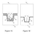
- FIG. 1A illustrates a cross-section of a tongue and groove prior to applying a welding process.
- FIG. 1B illustrates a cross-section of a tongue and groove joint after applying a welding process.
- FIG. 2A illustrates a cross-section of a shear joint prior to applying a welding process.
- FIG. 2B illustrates a cross-section of a shear joint after applying a welding process.
- FIG. 3 illustrates a perspective view of an assembled component enclosure after applying a welding process, consistent with embodiments disclosed herein.
- FIG. 4 illustrates a cross-section zoomed-in view of two component halves prior to applying a welding process, consistent with embodiments disclosed herein.
- FIG. 5 is a process flow chart describing a welding process consistent with embodiments disclosed herein.
- the present disclosure is directed towards a method for welding components together to form a watertight seal, and corresponding watertight components.
- these watertight components may be used to enclose and waterproof consumer electronics, such as activity monitoring devices, watches, computing devices, personal digital assistants (PDA), calculators, laptop computers, tablet computers, electronic toys and/or video games, electronics incorporated in articles of clothing, or other watertight components as known in the art.
- PDA personal digital assistants
- FIG. 1 One of ordinary skill in the art would appreciate that embodiments of the welding methods disclosed herein may also be applied to other tolerance dependent mechanical coupling applications.
- a method for watertight welding includes providing a first component half and a second component half.
- the first component half may include a groove on an outer edge shaped to accept a tenon structure during the welding process.
- the groove may be formed with two edge walls and a floor, wherein the floor includes a second groove or reservoir that may be used to collect excess bonding material created during the bonding process.
- the second component half may include a tenon structure (e.g., a tongue structure) shaped to match the profile of the groove on the first component half.
- the tenon structure may be located at an outer edge of the second component half, wherein the outer edge of the first component half may be designed to evenly contact the outer edge of the second component half when the tenon is completely disposed within the groove.
- the method further includes providing a with a protruding ridge extending from one of the edge walls of the groove.
- the protruding ridge may be formed using a bonding material designed to deform and melt at predetermined temperatures and pressures.
- the method may include providing a power source, such as an ultrasonic welding tool, a soldering iron, a resistive welding tool, an arc welding tool, a stick welding tool, a spot welding tool, a high temperature laser welding tool, or other types of welding tools and/or power sources as known in the art.
- the bonding material may be selected to have a melting point within the range of the specific welding tool or power source selected (e.g., the melting point may be within the range of heat developed when an ultrasonic power source causes the material to vibrate and heat up), as would be known in the art.
- the melting point of the bonding material may correlate to the bonding material's compressive strength and plasticity properties, such that the melting point may vary when compressive and/or shear forces are applied to the bonding material.
- the tenon may press against the protruding ridge when the tenon is inserted into the groove, such that the bonding material within the protruding ridge is placed under shear and/or compressive strain.
- the melting point may be vary based on this strain, and/or additional heat may be generated from the energy created from the strain.
- the method also includes moving the first component half towards the second component half such that the tenon slides inside (e.g., is disposed within) the groove while contacting the protruding ridge.
- the relative movement of the first component half and the second component half cause the tenon to press against the protruding ridge to generate the compressive and/or shear forces described above.
- the method may further include applying the heat source near the groove to cause the protruding ridge to transition to a liquid and/or transitional state while, at the same time, applying opposing vertical force to the first component half and the second component half.
- the deformation and/or melting of the protruding edge will remove oxidation and/or impurities at the surface of the protruding edge, and enable the bonding material to bond with both the inside of the groove and the outside of the tenon, effectively bonding the tenon to the groove.
- the length of the protruding edge thus, creates a sufficiently long bonding surface area to create a hermetic and/or watertight seal between the first component half and the second component half.
- the second groove structure formed on the floor of the first groove structure may act as a reservoir to catch excess bonding material created when the protruding edge transitions to a liquid state, enabling the remaining bonding material to flow and evenly fill the seam created between the outer walls of the tenon and the inner walls of the groove.
- the method also include cooling the bonding material such that the bonding material transitions back to a solid state.
- the bonding material may be metal, plastic, solder, or other bonding materials as would be known in the art.
- welding methods further include aligning the first component half with the second component half by bringing an outside lateral edge of the tenon in contact with an inside lateral edge of the groove.
- the inside lateral edge of the groove may protrude from a bottom surface of the first component half to enable the tenon to easily locate to and/or catch against the inside lateral edge when the first component half and the second component half are moved laterally with respect to each other. Once the tenon locates against the inside lateral edge of the groove, the tenon may slide along the inside lateral edge of the groove to maintain precision alignment between the first component half and the second component half.
- FIG. 1A illustrates a cross-section of a tongue and groove prior to applying a traditional welding process.
- first component half 100 includes a protruding tongue 110 .
- Protruding tongue 110 includes edge walls 112 and 116 , bottom wall 114 , and protruding energy director 118 .
- Second component half 150 includes a groove formed by inside groove walls 152 and 156 , and groove floor 154 .
- this example traditional bonding process starts with inserting tongue 110 into the groove in second component half 150 such that energy director 118 contacts groove floor 154 , such that the tongue 110 effectively aligns the first component half with the second component half.
- Inwardly opposing forces may then be applied to first component half 100 and second component half 150 , causing compressive pressure on energy director 118 as it is forced into groove floor 154 .
- a power source such as from a welding tool, may then be applied to cause a state transition on the surface of energy director 118 , while the compressive force causes energy director 118 to deform.
- This deformation and state transition e.g., from solid to liquid, or from solid to a transition state between solid and liquid
- FIG. 1B illustrates a cross-section of a tongue and groove joint after applying a welding process.
- groove 110 is now completely disposed within the groove formed by inside groove walls 152 and 156 , and groove floor 154 .
- a bond is formed at the contact point between tongue bottom wall 114 and groove floor 154 .
- the effective surface area of this bond is relatively small and is typically not hermetic, or even watertight in some examples.
- FIG. 2A illustrates a cross-section of a shear joint prior to applying a welding process.
- first component half 200 includes a protruding tongue 210 .
- Protruding tongue 210 includes edge walls 212 and 216 , and bottom wall 214 .
- Second component half 250 includes sidewall 252 , with extended sidewall portion 258 .
- extended sidewall portion 258 has a sloped or angled top surface to increase the mechanical advantage afforded to tongue 210 when it is forced downward and through extended sidewall portion 258 .
- This example traditional shear bonding process starts with forcing tongue 210 downward along sidewall 252 and over extended sidewall portion 258 , such that tongue 210 and second component half 250 telescope together, to wipe or deform extended sidewall portion 258 between tongue edge wall 212 and sidewall 252 .
- a heat source such as from a welding tool, may then be applied to cause a state transition on the surface of extended sidewall portion 258 .
- the resulting deformation and state transition (e.g., from solid to liquid, or from solid to a transition state between solid and liquid) effectively removes oxidation and surface impurities from the extended sidewall portion 258 surface, enabling a bond to form with tongue edge wall 212 .
- FIG. 2B illustrates a cross-section of a shear joint after applying a welding process.
- the bond surface area is relatively large in comparison to the tongue and groove welding method illustrated in FIGS. 1A and 1B , and accordingly, the shear joint bond may be hermetic, or at least watertight.
- to affect a quality bond sufficient to maintain a hermetic and/or watertight seal with an efficient yield requires maintenance of tight mechanical positioning tolerances of first component half 200 relative to second component half 250 during the welding process.
- a supporting fixture 260 must be used to control the lateral stability of second component half 250 relative to first component half 200 to increase tolerance control and yield.
- FIG. 3 illustrates a perspective view of an assembled component enclosure after applying a welding process.
- a first component half 300 couples to a second component half 350 using watertight bonds formed through a watertight bonding process consistent with embodiments disclosed herein.
- first component half may include a groove formed at one or more outside edges formed between an outside ridge structure 330 and an inside ridge structure 340 .
- Second component half 350 may include a tenon 360 (e.g, a tongue structure, or other tab, ridge, or protrusion configured to match the profile and form-fit within the groove formed between outside ridge structure 330 and inside ridge structure 340 ).
- first component half 300 may also include a protruding ridge structure 320 formed along an inner edge of either outside ridge structure 330 or inside ridge structure 340 .
- the protruding ridge structure 320 may be formed using a bonding material configured to change state from solid to liquid, or from solid to a transition state, when a heat source is applied at the same time that tenon 360 applies a compressive force to the protruding ridge structure 320 .
- tenon 360 slides into or disposed within the groove structure described, it will necessarily telescope along inside ridge structure 340 , wedging the bonding material to wedge between inside ridge structure 340 and tenon 360 . Accordingly, the bonding material will deform as it changes state and flow into the seam formed between inside ridge structure 340 and tenon 360 . When cooled, a hermetic and/or watertight bond is formed at the seam.
- inside ridge structure 340 may protrude vertically from first component half base relatively further than outside ridge structure 330 . Accordingly, the end of inside ridge structure 340 may be used as an alignment catch to locate and align tenon 360 when first component half 300 and second component half 350 move or slide laterally relative to each other.
- This self-aligning capability improves adherence to welding tolerances and, thus, increases welding efficiency and yield.
- the self-alignment process also eliminates the need to use supporting fixtures to maintain alignment between the first component half and second component half during the welding process.
- first component half 400 may include a first groove formed at one or more outside edges formed between an outside ridge structure 430 and an inside ridge structure 440 .
- first groove may be formed by boundary surfaces defined by inside surface 432 of outside ridge structure 430 , first groove floor 416 , and inside edge 442 of inside ridge structure 440 .
- a second groove, or reservoir may be formed between an inside surface 432 of outside ridge structure 430 , second groove floor 412 , and an inside groove surface 414 .
- the first component half 400 may also include protruding ridge 420 .
- protruding ridge 420 may be formed using a bonding material configured to change state from solid to liquid, or from solid to a transition state, when a heat source is applied.
- the heat source is a welding tool, such as an ultrasonic welding tool, a stick welding tool, an arc welding tool, a resistance welding tool, a spot welding tool, a soldering iron, a high temperature laser, or another welding tool or heat source as known in the art.
- the bonding material may be a material with chemical properties matching the desired heat and compressive pressure profile desired.
- the bonding material may be metal, thermoplastics, thermosets, glass, solder, or other bonding materials as known in the art.
- the bonding material is selected to be the same as, or compatible with, the material used to form the respective component halves (e.g., if the component halves are plastic, then the bonding material may also be plastic).
- second component half 450 may include a tenon 460 , defined by outside edge wall 464 , top surface 466 , and inside edge wall 468 .
- tenon 460 may be shaped to match the profile of the first groove formed between outside ridge structure 430 and inside ridge structure 440 .
- the heat source may be applied at the same time that a compressive force is applied to protruding ridge 420 to cause the bonding material to deform and transition to a liquid or transition state.
- the deformation and state change of the bonding material causes the removal of oxidation and surface impurities to enable bonding to an opposing surface (e.g., an inner edge wall 468 of tenon 460 ).
- an opposing surface e.g., an inner edge wall 468 of tenon 460
- the bonding material will deform as it changes state and flow into the seam formed between inside ridge structure 440 and tenon 460 , and bond to both inside ridge structure surface 442 and tenon edge wall 468 .
- excess bonding material that does not fit in the seam described may flow into the reservoir defined by the second groove (e.g., the second groove defined by inside surface 432 of outside ridge structure 430 , second groove floor 412 , and an inside groove surface 414 ).
- the bonding material is cooled, a hermetic and/or watertight bond is formed at the seam.
- FIG. 5 is a process flow chart describing a watertight welding process.
- a watertight welding process includes providing a first component with a first groove at step 505 and providing a second component with a tenon matching the profile of the first groove at step 535 .
- the first groove of step 505 may be consistent with the first groove structures defined between the inside ridge structures and outside ridge structures described with respect to FIGS. 3 and 4 above.
- the tenon of step 535 may be consistent with the tenon structures described with respect to FIGS. 3 and 4 above.
- the welding process may also include providing a protruding ridge within the first groove at step 525 .
- the protruding ridge may be formed using any of the bonding materials described above with respect to FIGS. 3 and 4 .
- the welding process may further include bringing the first component and the second component in contact with each other, such that the tenon form fits within the first groove at step 545 .
- the welding process may also include applying opposing vertical force to the first and second components to cause the protruding ridge to deform against one side of the tenon at step 555 .
- the welding process also includes applying a heat source to a seam between the tenon and the first groove to cause the deformed protruding ridge to melt and flow into the seam at step 565 .
- the process also includes a providing second groove structure within the first groove structure at step 515 .
- the second groove structure may be a reservoir used to capture excess bonding material created when the melted bonding material flows into the seam between the tenon and first groove.
- Several embodiments of the disclosure may further include a cooling the tenon and groove bond after the bonding material flows into the seam between the tenon and first groove such that the bonding material solidifies and forms a bond between one or more opposing surfaces of the tenon and the first groove.
- the heat source may be any welding tool and/or soldering iron as known in the art.
- some of the welding processes consistent with the process described with respect to FIG. 5 may be ultrasonic welding processes.
- a watertight ultrasonic welding process may include applying an ultrasonic welding tip to the outside ridge structure 430 of first component half 440 while applying vertically opposing forces to first component half 400 and second component half 450 to dispose tenon 460 into the first groove and deform protruding ridge structure 420 .
- the resulting compressive force on protruding ridge structure 420 in combination with the heat supplied by the ultrasonic welding tip may cause the bonding material that forms protruding ridge structure 420 to change states (e.g., solid to liquid), and form a bond between then inner edge of the tenon 460 and the outer edge of the inside ridge structure 440 .
- the ultrasonic welding tool may be substituted with other welding devices as would be known in the art.
- module does not imply that the components or functionality described or claimed as part of the module are all configured in a common package. Indeed, any or all of the various components of a module, whether control logic or other components, can be combined in a single package or separately maintained and can further be distributed in multiple groupings or packages or across multiple locations.
Landscapes
- Engineering & Computer Science (AREA)
- Mechanical Engineering (AREA)
- Physics & Mathematics (AREA)
- Optics & Photonics (AREA)
- Plasma & Fusion (AREA)
- Lining Or Joining Of Plastics Or The Like (AREA)
Abstract
Description
Claims (13)
Priority Applications (1)
| Application Number | Priority Date | Filing Date | Title |
|---|---|---|---|
| US14/583,084 US9849538B2 (en) | 2014-12-24 | 2014-12-24 | Watertight welding methods and components |
Applications Claiming Priority (1)
| Application Number | Priority Date | Filing Date | Title |
|---|---|---|---|
| US14/583,084 US9849538B2 (en) | 2014-12-24 | 2014-12-24 | Watertight welding methods and components |
Publications (2)
| Publication Number | Publication Date |
|---|---|
| US20160184933A1 US20160184933A1 (en) | 2016-06-30 |
| US9849538B2 true US9849538B2 (en) | 2017-12-26 |
Family
ID=56163158
Family Applications (1)
| Application Number | Title | Priority Date | Filing Date |
|---|---|---|---|
| US14/583,084 Active 2035-11-14 US9849538B2 (en) | 2014-12-24 | 2014-12-24 | Watertight welding methods and components |
Country Status (1)
| Country | Link |
|---|---|
| US (1) | US9849538B2 (en) |
Families Citing this family (7)
| Publication number | Priority date | Publication date | Assignee | Title |
|---|---|---|---|---|
| US10375846B2 (en) * | 2017-01-13 | 2019-08-06 | Lite-On Electronics (Guangzhou) Limited | Housing having housing parts bondable together and method of manufacturing the same |
| US10477710B2 (en) * | 2017-01-13 | 2019-11-12 | Lite-On Electronics (Guangzhou) Limited | Electronic module with an improved shell and method for making the same |
| CN109676141B (en) * | 2017-12-06 | 2020-10-23 | 全亿大科技(佛山)有限公司 | Manufacturing method of special-shaped complex metal product and special-shaped complex metal product |
| GB202108666D0 (en) * | 2018-09-28 | 2021-08-04 | Hgf Ltd | Single-sided ultrasonic welding mechanism and related techniques |
| CN112610349A (en) * | 2021-01-06 | 2021-04-06 | 广西方鑫技术有限公司 | Welding structure for plastic cylinder cover cap |
| CN114161021B (en) * | 2021-12-17 | 2023-08-15 | 中国电子科技集团公司第十三研究所 | A kind of sealing welding structure and welding method of hermetic micro-rectangular electrical connector |
| CN119468725B (en) * | 2025-01-15 | 2025-04-11 | 山西阿克斯太钢轧辊有限公司 | A cooling system with alarm protection function for metal smelting furnace |
Citations (49)
| Publication number | Priority date | Publication date | Assignee | Title |
|---|---|---|---|---|
| US2189096A (en) | 1938-07-07 | 1940-02-06 | Alonge Vera | Watch bracelet |
| US3543724A (en) | 1967-11-16 | 1970-12-01 | Max B Kirkpatrick | Monitored and controlled conditioning and exercise method for animals |
| US3978849A (en) | 1975-04-17 | 1976-09-07 | International Telephone And Telegraph Corporation | Pulse rate indicator |
| US4129124A (en) | 1976-03-23 | 1978-12-12 | Elektro-Apparatebau Olten A.G. | Pulse-rate indicator |
| US4224984A (en) | 1974-03-20 | 1980-09-30 | Sharp Kabushiki Kaisha | Finned tube useful for heat exchangers |
| US4307727A (en) | 1979-10-15 | 1981-12-29 | Tech Engineering And Design, Inc. | Wrist band transducer support and tensioning apparatus |
| US4331154A (en) | 1979-10-15 | 1982-05-25 | Tech Engineering & Design | Blood pressure and heart rate measuring watch |
| US4407295A (en) | 1980-10-16 | 1983-10-04 | Dna Medical, Inc. | Miniature physiological monitor with interchangeable sensors |
| US4409983A (en) | 1981-08-20 | 1983-10-18 | Albert David E | Pulse measuring device |
| US4491970A (en) | 1982-12-30 | 1985-01-01 | Lifeline Systems, Inc. | Portable transmitter for emergency alarm system having watertight enclosure |
| US5301154A (en) | 1992-07-16 | 1994-04-05 | Casio Computer Co., Ltd. | Time calculating device |
| US5392261A (en) | 1994-01-26 | 1995-02-21 | Hsu; Wen-Tung | Watch assembly |
| US5406952A (en) | 1993-02-11 | 1995-04-18 | Biosyss Corporation | Blood pressure monitoring system |
| US5524637A (en) | 1994-06-29 | 1996-06-11 | Erickson; Jon W. | Interactive system for measuring physiological exertion |
| US5734625A (en) | 1993-10-25 | 1998-03-31 | Seiko Epson Corporation | Portable apparatus |
| US5755623A (en) | 1995-12-21 | 1998-05-26 | Mizenko; John M. | Level accessory for golf putters |
| US5899370A (en) | 1997-02-13 | 1999-05-04 | Strokz Digital Sports, Inc. | Watchstrap |
| US6151968A (en) | 1998-01-16 | 2000-11-28 | Chou; Deng-Jeng | Wrist band type electronic sphygmomanometer |
| US6176953B1 (en) * | 1998-09-22 | 2001-01-23 | Motorola, Inc. | Ultrasonic welding process |
| US6361503B1 (en) | 2000-06-26 | 2002-03-26 | Mediwave Star Technology, Inc. | Method and system for evaluating cardiac ischemia |
| US20020151811A1 (en) | 2000-06-26 | 2002-10-17 | Starobin Joseph M. | Method and system for evaluating cardiac ischemia with heart rate feedback |
| US20020188210A1 (en) | 2001-06-11 | 2002-12-12 | Nobuyuki Aizawa | Pulse wave sensor and pulse rate detector |
| US20030065269A1 (en) | 2001-09-28 | 2003-04-03 | Csem Centre Suisse D'electronique Et De Microtechnique Sa | Method and device for pulse rate detection |
| US6736759B1 (en) | 1999-11-09 | 2004-05-18 | Paragon Solutions, Llc | Exercise monitoring system and methods |
| US20050056655A1 (en) | 2003-09-15 | 2005-03-17 | Gary Lonnie F. | Magnetic beverage holder |
| US20050116811A1 (en) | 2002-03-05 | 2005-06-02 | Masi Eros | Method for detecting the position and for confirming the identity of an individual |
| US20050256416A1 (en) | 2004-05-12 | 2005-11-17 | Chen Yu Y | Heart rate detecting and displaying device |
| US20060183980A1 (en) | 2005-02-14 | 2006-08-17 | Chang-Ming Yang | Mental and physical health status monitoring, analyze and automatic follow up methods and its application on clothing |
| US7192401B2 (en) | 2002-08-16 | 2007-03-20 | Firstbeat Technologies Oy | Method for monitoring accumulated body fatigue for determining recovery during exercise or activity |
| US20070118043A1 (en) | 2005-11-23 | 2007-05-24 | Microsoft Corporation | Algorithms for computing heart rate and movement speed of a user from sensor data |
| US20080132383A1 (en) | 2004-12-07 | 2008-06-05 | Tylerton International Inc. | Device And Method For Training, Rehabilitation And/Or Support |
| US20080228089A1 (en) | 2007-03-12 | 2008-09-18 | Samsung Electronics Co., Ltd. | Method and apparatus for cufflessly and non-invasively measuring wrist blood pressure in association with communication device |
| US20090312656A1 (en) | 2008-06-13 | 2009-12-17 | Salutron, Inc. | Electrostatic Discharge Protection For Wrist-Worn Device |
| US7717827B2 (en) | 2006-03-03 | 2010-05-18 | Firstbeat Technologies Oy | Method and system for controlling training |
| US20100197463A1 (en) | 2009-01-30 | 2010-08-05 | Apple Inc. | Systems and methods for providing automated workout reminders |
| US20110021319A1 (en) | 2008-03-27 | 2011-01-27 | Polar Electro Oy | Apparatus for Metabolic Training Load, Mechanical Stimulus, and Recovery Time Calculation |
| US7914425B2 (en) | 2004-10-22 | 2011-03-29 | Mytrak Health System Inc. | Hydraulic exercise machine system and methods thereof |
| US20110092790A1 (en) | 2009-10-16 | 2011-04-21 | Oliver Wilder-Smith | Biosensor module with leadless contacts |
| US20110260870A1 (en) | 2010-04-21 | 2011-10-27 | Melanie Bailey | Method of preventing an inmate from committing suicide |
| US20120022341A1 (en) | 2010-02-01 | 2012-01-26 | Mark Zdeblick | Two-Wrist Data Gathering System |
| US20120168471A1 (en) | 2011-01-05 | 2012-07-05 | Wimo Labs LLC | Electronic Device Holder |
| US20120253485A1 (en) | 2010-11-01 | 2012-10-04 | Nike, Inc. | Wearable Device Having Athletic Functionality |
| US20130064049A1 (en) | 2011-09-13 | 2013-03-14 | Ocean Reef, Inc. | Watch with shapeable strap |
| US20130237778A1 (en) | 2010-11-19 | 2013-09-12 | Centre National D'etudes Spatiales (Cnes) | Exercise-assisting device for forecasting the change in a physiological parameter as a function of an itinerary |
| US20140032234A1 (en) | 2012-07-26 | 2014-01-30 | VaporWire, LLC | Health and wellness system |
| US20140073486A1 (en) | 2012-09-04 | 2014-03-13 | Bobo Analytics, Inc. | Systems, devices and methods for continuous heart rate monitoring and interpretation |
| US20140107493A1 (en) | 2012-06-22 | 2014-04-17 | Fitbit, Inc. | Portable Biometric Monitoring Devices and Methods of Operating Same |
| US20140228175A1 (en) | 2009-10-26 | 2014-08-14 | The Personal Trainer, Inc. | Tension Systems and Methods of Use |
| US8992385B2 (en) | 2009-10-26 | 2015-03-31 | Personal Trainer, Inc. | Tension systems and methods of use |
-
2014
- 2014-12-24 US US14/583,084 patent/US9849538B2/en active Active
Patent Citations (49)
| Publication number | Priority date | Publication date | Assignee | Title |
|---|---|---|---|---|
| US2189096A (en) | 1938-07-07 | 1940-02-06 | Alonge Vera | Watch bracelet |
| US3543724A (en) | 1967-11-16 | 1970-12-01 | Max B Kirkpatrick | Monitored and controlled conditioning and exercise method for animals |
| US4224984A (en) | 1974-03-20 | 1980-09-30 | Sharp Kabushiki Kaisha | Finned tube useful for heat exchangers |
| US3978849A (en) | 1975-04-17 | 1976-09-07 | International Telephone And Telegraph Corporation | Pulse rate indicator |
| US4129124A (en) | 1976-03-23 | 1978-12-12 | Elektro-Apparatebau Olten A.G. | Pulse-rate indicator |
| US4307727A (en) | 1979-10-15 | 1981-12-29 | Tech Engineering And Design, Inc. | Wrist band transducer support and tensioning apparatus |
| US4331154A (en) | 1979-10-15 | 1982-05-25 | Tech Engineering & Design | Blood pressure and heart rate measuring watch |
| US4407295A (en) | 1980-10-16 | 1983-10-04 | Dna Medical, Inc. | Miniature physiological monitor with interchangeable sensors |
| US4409983A (en) | 1981-08-20 | 1983-10-18 | Albert David E | Pulse measuring device |
| US4491970A (en) | 1982-12-30 | 1985-01-01 | Lifeline Systems, Inc. | Portable transmitter for emergency alarm system having watertight enclosure |
| US5301154A (en) | 1992-07-16 | 1994-04-05 | Casio Computer Co., Ltd. | Time calculating device |
| US5406952A (en) | 1993-02-11 | 1995-04-18 | Biosyss Corporation | Blood pressure monitoring system |
| US5734625A (en) | 1993-10-25 | 1998-03-31 | Seiko Epson Corporation | Portable apparatus |
| US5392261A (en) | 1994-01-26 | 1995-02-21 | Hsu; Wen-Tung | Watch assembly |
| US5524637A (en) | 1994-06-29 | 1996-06-11 | Erickson; Jon W. | Interactive system for measuring physiological exertion |
| US5755623A (en) | 1995-12-21 | 1998-05-26 | Mizenko; John M. | Level accessory for golf putters |
| US5899370A (en) | 1997-02-13 | 1999-05-04 | Strokz Digital Sports, Inc. | Watchstrap |
| US6151968A (en) | 1998-01-16 | 2000-11-28 | Chou; Deng-Jeng | Wrist band type electronic sphygmomanometer |
| US6176953B1 (en) * | 1998-09-22 | 2001-01-23 | Motorola, Inc. | Ultrasonic welding process |
| US6736759B1 (en) | 1999-11-09 | 2004-05-18 | Paragon Solutions, Llc | Exercise monitoring system and methods |
| US6361503B1 (en) | 2000-06-26 | 2002-03-26 | Mediwave Star Technology, Inc. | Method and system for evaluating cardiac ischemia |
| US20020151811A1 (en) | 2000-06-26 | 2002-10-17 | Starobin Joseph M. | Method and system for evaluating cardiac ischemia with heart rate feedback |
| US20020188210A1 (en) | 2001-06-11 | 2002-12-12 | Nobuyuki Aizawa | Pulse wave sensor and pulse rate detector |
| US20030065269A1 (en) | 2001-09-28 | 2003-04-03 | Csem Centre Suisse D'electronique Et De Microtechnique Sa | Method and device for pulse rate detection |
| US20050116811A1 (en) | 2002-03-05 | 2005-06-02 | Masi Eros | Method for detecting the position and for confirming the identity of an individual |
| US7192401B2 (en) | 2002-08-16 | 2007-03-20 | Firstbeat Technologies Oy | Method for monitoring accumulated body fatigue for determining recovery during exercise or activity |
| US20050056655A1 (en) | 2003-09-15 | 2005-03-17 | Gary Lonnie F. | Magnetic beverage holder |
| US20050256416A1 (en) | 2004-05-12 | 2005-11-17 | Chen Yu Y | Heart rate detecting and displaying device |
| US7914425B2 (en) | 2004-10-22 | 2011-03-29 | Mytrak Health System Inc. | Hydraulic exercise machine system and methods thereof |
| US20080132383A1 (en) | 2004-12-07 | 2008-06-05 | Tylerton International Inc. | Device And Method For Training, Rehabilitation And/Or Support |
| US20060183980A1 (en) | 2005-02-14 | 2006-08-17 | Chang-Ming Yang | Mental and physical health status monitoring, analyze and automatic follow up methods and its application on clothing |
| US20070118043A1 (en) | 2005-11-23 | 2007-05-24 | Microsoft Corporation | Algorithms for computing heart rate and movement speed of a user from sensor data |
| US7717827B2 (en) | 2006-03-03 | 2010-05-18 | Firstbeat Technologies Oy | Method and system for controlling training |
| US20080228089A1 (en) | 2007-03-12 | 2008-09-18 | Samsung Electronics Co., Ltd. | Method and apparatus for cufflessly and non-invasively measuring wrist blood pressure in association with communication device |
| US20110021319A1 (en) | 2008-03-27 | 2011-01-27 | Polar Electro Oy | Apparatus for Metabolic Training Load, Mechanical Stimulus, and Recovery Time Calculation |
| US20090312656A1 (en) | 2008-06-13 | 2009-12-17 | Salutron, Inc. | Electrostatic Discharge Protection For Wrist-Worn Device |
| US20100197463A1 (en) | 2009-01-30 | 2010-08-05 | Apple Inc. | Systems and methods for providing automated workout reminders |
| US20110092790A1 (en) | 2009-10-16 | 2011-04-21 | Oliver Wilder-Smith | Biosensor module with leadless contacts |
| US20140228175A1 (en) | 2009-10-26 | 2014-08-14 | The Personal Trainer, Inc. | Tension Systems and Methods of Use |
| US8992385B2 (en) | 2009-10-26 | 2015-03-31 | Personal Trainer, Inc. | Tension systems and methods of use |
| US20120022341A1 (en) | 2010-02-01 | 2012-01-26 | Mark Zdeblick | Two-Wrist Data Gathering System |
| US20110260870A1 (en) | 2010-04-21 | 2011-10-27 | Melanie Bailey | Method of preventing an inmate from committing suicide |
| US20120253485A1 (en) | 2010-11-01 | 2012-10-04 | Nike, Inc. | Wearable Device Having Athletic Functionality |
| US20130237778A1 (en) | 2010-11-19 | 2013-09-12 | Centre National D'etudes Spatiales (Cnes) | Exercise-assisting device for forecasting the change in a physiological parameter as a function of an itinerary |
| US20120168471A1 (en) | 2011-01-05 | 2012-07-05 | Wimo Labs LLC | Electronic Device Holder |
| US20130064049A1 (en) | 2011-09-13 | 2013-03-14 | Ocean Reef, Inc. | Watch with shapeable strap |
| US20140107493A1 (en) | 2012-06-22 | 2014-04-17 | Fitbit, Inc. | Portable Biometric Monitoring Devices and Methods of Operating Same |
| US20140032234A1 (en) | 2012-07-26 | 2014-01-30 | VaporWire, LLC | Health and wellness system |
| US20140073486A1 (en) | 2012-09-04 | 2014-03-13 | Bobo Analytics, Inc. | Systems, devices and methods for continuous heart rate monitoring and interpretation |
Non-Patent Citations (3)
| Title |
|---|
| "Elite Clock Military Style LED Watch" by ledwatchsuk. YouTube [dated May 31, 2011][online][retrieved on Aug. 14, 2015]. |
| "Watch Stylish Blue Light LED Round Dial Matrix Stainless from ChinaBuye.com" by YnopoB. YouTube [dated Apr. 23, 2012][online][retrieved on Dec. 31, 2015] (https://www.youtube.com/watch?v=e-LWbXHvvWg). |
| "Watch Stylish Blue Light LED Round Dial Matrix Stainless from ChinaBuye.com" by YnopoB. YouTube [dated Apr. 23, 2012][online][retrieved on Dec. 31, 2015] (https://www.youtube.com/watch?v=e—LWbXHvvWg). |
Also Published As
| Publication number | Publication date |
|---|---|
| US20160184933A1 (en) | 2016-06-30 |
Similar Documents
| Publication | Publication Date | Title |
|---|---|---|
| US9849538B2 (en) | Watertight welding methods and components | |
| US12461566B2 (en) | High tolerance connection between elements | |
| US11573608B2 (en) | High tolerance connection between elements | |
| JP4894784B2 (en) | Semiconductor device and manufacturing method thereof | |
| KR102002551B1 (en) | Manufacturing method for battery housing for electric vehicle and structure for joining battery cover | |
| JP6854401B2 (en) | Conductor joints and electronic components using them and their manufacturing methods | |
| US20070050980A1 (en) | Method for manufacturing a CPU cooling assembly | |
| CN205680039U (en) | Electronic device | |
| CN101150887A (en) | Ultrasonic welding method for loudspeaker casing | |
| JP2015213945A (en) | Ultrasonic bonding method | |
| US20090226703A1 (en) | Adhesive bonding assembly and method for making the same | |
| US9403318B2 (en) | Heat stake joining of adhesively bonded thermoplastic components | |
| KR101940150B1 (en) | Sealing apparatus for secondary battery | |
| JP2004142136A (en) | Ultrasonic welding method for resin package | |
| US9607739B2 (en) | Method for bonding flat cable and bonding object, ultrasonic bonding device, and cable | |
| CN218111782U (en) | Bonding structure and bonding module | |
| KR20060107296A (en) | Case joining method of plate heat transfer apparatus and apparatus manufactured by the method | |
| US20130263998A1 (en) | Ultrasonic welding structure and ultrasonic welding method | |
| JP2017024060A (en) | Method for joining metal and non-metal material | |
| JP6424665B2 (en) | Method of manufacturing joined structure | |
| US11968790B1 (en) | Housing construction for snap-in retention | |
| JP2012151198A (en) | Structure for jointing bus bar and wiring | |
| JP6271940B2 (en) | Vibration welding apparatus and article manufacturing method | |
| KR101303495B1 (en) | Piezo for actuator and method for manufacturing the same | |
| JP2001277363A (en) | Method for welding resin member |
Legal Events
| Date | Code | Title | Description |
|---|---|---|---|
| AS | Assignment |
Owner name: JAYBIRD LLC, CALIFORNIA Free format text: ASSIGNMENT OF ASSIGNORS INTEREST;ASSIGNORS:ARMSTRONG, JUDD;DUDDY, STEPHEN;REEL/FRAME:035131/0783 Effective date: 20150226 |
|
| AS | Assignment |
Owner name: LOGITECH EUROPE, S.A., SWITZERLAND Free format text: ASSIGNMENT OF ASSIGNORS INTEREST;ASSIGNOR:JAYBIRD, LLC;REEL/FRAME:039414/0683 Effective date: 20160719 |
|
| FEPP | Fee payment procedure |
Free format text: ENTITY STATUS SET TO UNDISCOUNTED (ORIGINAL EVENT CODE: BIG.) |
|
| STCF | Information on status: patent grant |
Free format text: PATENTED CASE |
|
| MAFP | Maintenance fee payment |
Free format text: PAYMENT OF MAINTENANCE FEE, 4TH YEAR, LARGE ENTITY (ORIGINAL EVENT CODE: M1551); ENTITY STATUS OF PATENT OWNER: LARGE ENTITY Year of fee payment: 4 |
|
| MAFP | Maintenance fee payment |
Free format text: PAYMENT OF MAINTENANCE FEE, 8TH YEAR, LARGE ENTITY (ORIGINAL EVENT CODE: M1552); ENTITY STATUS OF PATENT OWNER: LARGE ENTITY Year of fee payment: 8 |