US9847606B2 - Electrical connector having extended separating wall portion for preventing insertion of uncut terminals - Google Patents
Electrical connector having extended separating wall portion for preventing insertion of uncut terminals Download PDFInfo
- Publication number
- US9847606B2 US9847606B2 US15/462,936 US201715462936A US9847606B2 US 9847606 B2 US9847606 B2 US 9847606B2 US 201715462936 A US201715462936 A US 201715462936A US 9847606 B2 US9847606 B2 US 9847606B2
- Authority
- US
- United States
- Prior art keywords
- terminal
- pair
- terminals
- receiving
- insulative housing
- Prior art date
- Legal status (The legal status is an assumption and is not a legal conclusion. Google has not performed a legal analysis and makes no representation as to the accuracy of the status listed.)
- Active
Links
Images


Classifications
-
- H—ELECTRICITY
- H01—ELECTRIC ELEMENTS
- H01R—ELECTRICALLY-CONDUCTIVE CONNECTIONS; STRUCTURAL ASSOCIATIONS OF A PLURALITY OF MUTUALLY-INSULATED ELECTRICAL CONNECTING ELEMENTS; COUPLING DEVICES; CURRENT COLLECTORS
- H01R13/00—Details of coupling devices of the kinds covered by groups H01R12/70 or H01R24/00 - H01R33/00
- H01R13/46—Bases; Cases
-
- H—ELECTRICITY
- H01—ELECTRIC ELEMENTS
- H01R—ELECTRICALLY-CONDUCTIVE CONNECTIONS; STRUCTURAL ASSOCIATIONS OF A PLURALITY OF MUTUALLY-INSULATED ELECTRICAL CONNECTING ELEMENTS; COUPLING DEVICES; CURRENT COLLECTORS
- H01R13/00—Details of coupling devices of the kinds covered by groups H01R12/70 or H01R24/00 - H01R33/00
- H01R13/648—Protective earth or shield arrangements on coupling devices, e.g. anti-static shielding
- H01R13/658—High frequency shielding arrangements, e.g. against EMI [Electro-Magnetic Interference] or EMP [Electro-Magnetic Pulse]
- H01R13/6581—Shield structure
- H01R13/6585—Shielding material individually surrounding or interposed between mutually spaced contacts
-
- H—ELECTRICITY
- H01—ELECTRIC ELEMENTS
- H01R—ELECTRICALLY-CONDUCTIVE CONNECTIONS; STRUCTURAL ASSOCIATIONS OF A PLURALITY OF MUTUALLY-INSULATED ELECTRICAL CONNECTING ELEMENTS; COUPLING DEVICES; CURRENT COLLECTORS
- H01R13/00—Details of coupling devices of the kinds covered by groups H01R12/70 or H01R24/00 - H01R33/00
- H01R13/02—Contact members
-
- H—ELECTRICITY
- H01—ELECTRIC ELEMENTS
- H01R—ELECTRICALLY-CONDUCTIVE CONNECTIONS; STRUCTURAL ASSOCIATIONS OF A PLURALITY OF MUTUALLY-INSULATED ELECTRICAL CONNECTING ELEMENTS; COUPLING DEVICES; CURRENT COLLECTORS
- H01R13/00—Details of coupling devices of the kinds covered by groups H01R12/70 or H01R24/00 - H01R33/00
- H01R13/648—Protective earth or shield arrangements on coupling devices, e.g. anti-static shielding
- H01R13/658—High frequency shielding arrangements, e.g. against EMI [Electro-Magnetic Interference] or EMP [Electro-Magnetic Pulse]
- H01R13/6591—Specific features or arrangements of connection of shield to conductive members
- H01R13/6594—Specific features or arrangements of connection of shield to conductive members the shield being mounted on a PCB and connected to conductive members
-
- H—ELECTRICITY
- H01—ELECTRIC ELEMENTS
- H01R—ELECTRICALLY-CONDUCTIVE CONNECTIONS; STRUCTURAL ASSOCIATIONS OF A PLURALITY OF MUTUALLY-INSULATED ELECTRICAL CONNECTING ELEMENTS; COUPLING DEVICES; CURRENT COLLECTORS
- H01R24/00—Two-part coupling devices, or either of their cooperating parts, characterised by their overall structure
- H01R24/60—Contacts spaced along planar side wall transverse to longitudinal axis of engagement
-
- H—ELECTRICITY
- H01—ELECTRIC ELEMENTS
- H01R—ELECTRICALLY-CONDUCTIVE CONNECTIONS; STRUCTURAL ASSOCIATIONS OF A PLURALITY OF MUTUALLY-INSULATED ELECTRICAL CONNECTING ELEMENTS; COUPLING DEVICES; CURRENT COLLECTORS
- H01R43/00—Apparatus or processes specially adapted for manufacturing, assembling, maintaining, or repairing of line connectors or current collectors or for joining electric conductors
- H01R43/20—Apparatus or processes specially adapted for manufacturing, assembling, maintaining, or repairing of line connectors or current collectors or for joining electric conductors for assembling or disassembling contact members with insulating base, case or sleeve
-
- H—ELECTRICITY
- H01—ELECTRIC ELEMENTS
- H01R—ELECTRICALLY-CONDUCTIVE CONNECTIONS; STRUCTURAL ASSOCIATIONS OF A PLURALITY OF MUTUALLY-INSULATED ELECTRICAL CONNECTING ELEMENTS; COUPLING DEVICES; CURRENT COLLECTORS
- H01R12/00—Structural associations of a plurality of mutually-insulated electrical connecting elements, specially adapted for printed circuits, e.g. printed circuit boards [PCB], flat or ribbon cables, or like generally planar structures, e.g. terminal strips, terminal blocks; Coupling devices specially adapted for printed circuits, flat or ribbon cables, or like generally planar structures; Terminals specially adapted for contact with, or insertion into, printed circuits, flat or ribbon cables, or like generally planar structures
- H01R12/70—Coupling devices
- H01R12/71—Coupling devices for rigid printing circuits or like structures
- H01R12/72—Coupling devices for rigid printing circuits or like structures coupling with the edge of the rigid printed circuits or like structures
- H01R12/722—Coupling devices for rigid printing circuits or like structures coupling with the edge of the rigid printed circuits or like structures coupling devices mounted on the edge of the printed circuits
- H01R12/724—Coupling devices for rigid printing circuits or like structures coupling with the edge of the rigid printed circuits or like structures coupling devices mounted on the edge of the printed circuits containing contact members forming a right angle
-
- H—ELECTRICITY
- H01—ELECTRIC ELEMENTS
- H01R—ELECTRICALLY-CONDUCTIVE CONNECTIONS; STRUCTURAL ASSOCIATIONS OF A PLURALITY OF MUTUALLY-INSULATED ELECTRICAL CONNECTING ELEMENTS; COUPLING DEVICES; CURRENT COLLECTORS
- H01R2107/00—Four or more poles
Definitions
- the present invention relates to an electrical connector having an insulative housing designed to prevent insertion of terminals where cutoff bridges have not been removed.
- the electrical connector includes a first module, a second module mounted to the first module, and a shell.
- the first module has a first insulator, a number of first contacts, and a shielding plate retained in the first insulator.
- the first insulator has a tongue portion defining a first surface and a second surface.
- the second surface defines a number of slots.
- the second module has a second insulator and a number of second contacts retained in the second insulator. The first contacts are exposed from the first surface and the second contacts are received in the slots and exposed from the second surface.
- U.S. Patent Application Publication No. 2016/0020568 discloses a reversible electrical connector including a body, plural terminals fixedly disposed in the body, and a metal casing covering the body.
- the terminals are divided into an upper and a lower row, which are each insert molded with an insulation block to form an upper terminal module and a lower terminal module.
- One object of the present invention is to provide an electrical connector, comprising: an insulative housing having a base portion and a tongue portion extending forwardly from the base portion, the tongue portion having a plurality of terminal-receiving slots, a respective separating wall being disposed between every two neighboring terminal-receiving slots, at least one separating wall having an extending portion extending backwardly along an insertion direction to be located behind respective rear ends of the other separating walls; a plurality of terminals retained in the insulative housing, the plurality of terminals including a row of first contacts, each first contact having a pair of gaps located forwardly of the extending portion along the insertion direction; a metallic shielding plate retained in the insulative housing; and a shielding shell attached to the insulative housing.
- FIG. 1 is a perspective, assembled view of an electrical connector
- FIG. 2 is another perspective, assembled view of FIG. 1 ;
- FIG. 3 is a perspective view of the electrical connector separated with a shielding shell
- FIG. 4 is another perspective view of FIG. 3 ;
- FIG. 5 is a perspective, partly exploded view of the electrical connector
- FIG. 6 is another perspective, partly exploded view of FIG. 5 ;
- FIG. 7 is a cross-sectional view along line 7 - 7 of FIG. 3 ;
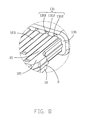
- FIG. 8 is an amplified partly view of B in FIG. 3 ;
- FIG. 9 is a perspective view of an insulator and a number of first contacts connected with metal carriers.
- FIG. 10 is a cross-sectional view of an insulative housing, the insulator, and the first contacts connected with metal carriers.
- FIGS. 1 to 8 show an electrical connector 100 cooperated with a plug connector.
- the electronic connector 100 defines a mating port, an insertion direction, a transverse direction perpendicular to the insertion direction and forming a horizontal plane therebetween, and a vertical direction perpendicular to the insertion direction and the transverse direction in FIG. 1 .
- the electrical connector 100 includes an insulative housing 1 , a number of terminals 2 and a metallic shielding plate 3 retained in the insulative housing 1 , an insulator 4 received in the insulative housing 1 , and a shielding shell 5 attached to the insulative housing 1 .
- the insulative housing 1 includes a base portion 11 defining a receiving cavity 110 and a tongue portion 12 extending forwardly from the base portion 11 .
- the base portion 11 has a pair of receiving holes 112 communicated with an upper surface and a lower surface thereof, a pair of projections 113 located behind the receiving holes 112 , and a division 114 located at a rear end thereof.
- the tongue portion 12 defines a first surface 121 and a second surface 122 disposed oppositely, and a number of terminal-receiving slots 120 extending along the insertion direction and located at the first surface 121 and the second surface 122 .
- the neighboring terminal-receiving slots 120 located at the first surface 121 define a separating wall 123 .
- Two of the separating walls 123 located at symmetrical positions respectively define a pair of extending portions 124 extending backwardly therefrom.
- the extending portions 124 and other separating walls 123 define a number of guiding portions 125 located at a rear end.
- Each guiding portion 125 defines a pair of inclined surfaces 126 guiding the terminals 2 into the terminal-receiving slots 120 located at the first surface 121 correctly.
- the tongue portion 12 defines a connection 130 connected with the base portion 11 .
- the connection 130 has a number of resisting structures 131 .
- Each resisting structure 131 has an aperture 1311 located above the terminal-receiving slot 120 and communicated with the corresponding terminal-receiving slot 120 and a pair of stepping portions 1312 located between the aperture 1311 and the corresponding terminal-receiving slot 120 and resisted against by the corresponding terminal 2 .
- the pair of stepping portions 1312 are disposed discontinuously and resists two sides of the corresponding terminal 2 along the transverse direction.
- the division 114 divides rear openings of the terminal-receiving slots 120 located at the first surface 121 and the second surface 122 along the vertical direction.
- the terminals 2 include a number of first contacts 21 carried by the first surface 121 of the tongue portion 12 and a number of second contacts 22 carried by the second surface 122 of the tongue portion 12 .
- the first contacts 21 and the second contacts 22 extending in an insertion direction respectively includes four power contacts located forwardly and eight signal contacts located backwardly.
- the two power contacts in the middle are used to provide electric source and the other two are used for electrical grounding.
- the eight signal contacts includes four super-speed differential contacts located at two sides, two low-speed differential contacts located in the middle, and a pair of controlling contacts.
- Each of the first contacts 21 is associated with a respective one of the second contacts 22 and is positioned in reverse symmetry with respect to the second contacts 22 .
- Each of the first contacts 21 includes a first contacting portion 211 exposed from the first surface 121 , a first affixed portion 212 extending along the insertion direction, and a first soldering portion 213 extending from a back end of the insulator 4 .
- the first contacts 21 are insert-molded with the insulator 4 to form a terminal module wholly and the first affixed portions 212 are retained in the insulator 4 .
- Each of the second contacts 22 shaping like a panel includes a second contacting portion 221 exposed from the second surface 122 of the tongue portion 12 , a second affixed portion 222 retained in the tongue portion 12 , and a second soldering portion 223 extending from a back end of the base portion 11 .
- Each of the second contacts 22 has a tail portion 224 extending backwardly from the second affixed portion 222 and separated from the second soldering portion 223 .
- the tail portions 224 are used for pressing and orienting and prevent interfering with the orienting and forming of the second soldering portions 223 in bending the second soldering portions 223 .
- Each of the first contacts 21 and the second contacts 22 respectively has an end portion 23 extending close to the metallic shielding plate 3 so that the terminals 2 are incapable of up-warping to scrape or null contact.
- Each of the first contact 21 defines a number of metal carriers 215 connected therewith before cutting off and a number of gaps 216 formed after cutting off the metal carriers 215 .
- Each extending portion 124 of the insulative housing is located between the neighboring gaps 216 of the first contacts 21 .
- the guiding portions 125 of the extending portions 124 are resisted against by the metal carriers 215 to prevent the insulator 4 with the first contacts 21 inserting into the insulative housing 1 , when the first contacts 21 still mistakenly connected with the metal carriers are insert-molded with the insulator 4 .
- Two sides of the first affixed portions 212 are resisted against by low surfaces of the two stepping portions 1312 to release pressure form the stepping portions 1312 and prevent the first contacting portion 211 tilting upwardly pressed by downward pressure of the first affixed portions 212 .
- the metallic shielding plate 3 sandwiched between the first contacts 22 and the second contacts 22 , includes a supporting portion 31 retained in the insulative housing 1 and a pair of affixed legs 32 extending downwardly from a rear end of the supporting portion 31 .
- the insulator 4 has a number of ribs 41 resisting an inner surface of the receiving cavity 110 of the insulative housing 1 to affix the insulator 4 stably with the insulative housing 1 .
- the insulator 4 has a number of protrusions 42 located at two sides thereof and a number of depressions 43 adjacent to the projections 42 .
- the projections 42 protrude to the receiving holes 112 of the insulative housing 1 and the projections 113 are received in the depressions 43 to orient the insulator 4 in the insulative housing 1 and prevent the insulator 4 withdrawing.
- the receiving holes 112 are used to observe the assembly of the insulator 4 and the insulative housing 1 .
- the shielding shell 5 includes opposite top wall 51 and bottom wall 52 , and a pair of side walls 53 linked therebetween by two sides. Each of the top wall 51 and the bottom wall 52 has an inward retention arm 55 .
- the top wall 51 has a plurality of dimples 54 for engagement with the shell of the complementary connector.
- a method of making the electrical connector 100 includes the steps of: providing a metallic shielding plate 3 , insert-molding the insulative housing 1 with the metallic shielding plate 3 , the neighboring terminal-receiving slots 120 define a separating wall 123 located therebetween, a pair of the separating walls 123 having the extending portion 124 extending backwardly from a rear end thereof and located behind the other separating walls 123 along the insertion direction; providing a number of second contacts 22 , assembling the second contacts 22 to the terminal-receiving slots 120 located at the second surface 122 ; providing a number of first contacts 21 connected with the metal carriers 215 , insert-molding the insulator 4 with the first contacts 21 connected with the metal carriers 215 ; cutting off the metal carriers 215 between the neighboring first contacts 21 to form a pair of gaps 216 located at two sides of the first contacts 21 ; assembling the insulator 4 with the first contacts 21 to the insulative housing 1 to dispose the first contacts 21 in the terminal-receiving slots
Landscapes
- Engineering & Computer Science (AREA)
- Manufacturing & Machinery (AREA)
- Details Of Connecting Devices For Male And Female Coupling (AREA)
- Connector Housings Or Holding Contact Members (AREA)
- Manufacturing Of Electrical Connectors (AREA)
Abstract
Description
Claims (7)
Applications Claiming Priority (3)
| Application Number | Priority Date | Filing Date | Title |
|---|---|---|---|
| CN201610155325 | 2016-03-18 | ||
| CN201610155325.6A CN107204533B (en) | 2016-03-18 | 2016-03-18 | Electric connector and its manufacturing method |
| CN201610155325.6 | 2016-03-18 |
Publications (2)
| Publication Number | Publication Date |
|---|---|
| US20170271821A1 US20170271821A1 (en) | 2017-09-21 |
| US9847606B2 true US9847606B2 (en) | 2017-12-19 |
Family
ID=59847157
Family Applications (1)
| Application Number | Title | Priority Date | Filing Date |
|---|---|---|---|
| US15/462,936 Active US9847606B2 (en) | 2016-03-18 | 2017-03-20 | Electrical connector having extended separating wall portion for preventing insertion of uncut terminals |
Country Status (4)
| Country | Link |
|---|---|
| US (1) | US9847606B2 (en) |
| JP (1) | JP2017174797A (en) |
| CN (1) | CN107204533B (en) |
| TW (1) | TW201735460A (en) |
Cited By (1)
| Publication number | Priority date | Publication date | Assignee | Title |
|---|---|---|---|---|
| US9979102B2 (en) * | 2016-06-28 | 2018-05-22 | Foxconn Interconnect Technology Limited | Electrical connector assembly |
Families Citing this family (7)
| Publication number | Priority date | Publication date | Assignee | Title |
|---|---|---|---|---|
| CN107834252B (en) * | 2017-11-10 | 2020-06-05 | 番禺得意精密电子工业有限公司 | Electrical connector |
| CN109830833B (en) * | 2017-11-23 | 2021-11-19 | 富士康(昆山)电脑接插件有限公司 | Electric connector and terminal module assembly thereof |
| CN109119842B (en) * | 2018-09-18 | 2024-07-19 | 昆山全方位电子科技有限公司 | Electric connector |
| CN111129807B (en) * | 2018-10-30 | 2023-02-28 | 富士康(昆山)电脑接插件有限公司 | Electrical connector |
| CN109787065B (en) * | 2019-01-02 | 2019-12-10 | 深圳市创益通技术股份有限公司 | intelligent manufacturing production process of Type-C connector |
| EP3930112A1 (en) * | 2020-06-24 | 2021-12-29 | Rosenberger Hochfrequenztechnik GmbH & Co. KG | Electric connector and method for mounting of a connector |
| TWM616319U (en) * | 2021-03-17 | 2021-09-01 | 詮欣股份有限公司 | Connector |
Citations (10)
| Publication number | Priority date | Publication date | Assignee | Title |
|---|---|---|---|---|
| US20100173529A1 (en) * | 2009-01-05 | 2010-07-08 | Hon Hai Precision Industry Co., Ltd. | Electrical connector with improved contacts |
| US20110076895A1 (en) * | 2007-08-10 | 2011-03-31 | Hon Hai Precision Industry Co., Ltd. | Electrical connector with improved contact arrangement |
| US8635097B2 (en) * | 2007-03-30 | 2014-01-21 | Fuji Xerox Co., Ltd. | Schedule warning system, schedule warning method and medium storing schedule warning program |
| US8740649B2 (en) * | 2012-07-30 | 2014-06-03 | Cheng Uei Precision Industry Co., Ltd. | Electrical connector |
| CN203859329U (en) | 2014-05-30 | 2014-10-01 | 上海莫仕连接器有限公司 | Electrical connector |
| US8882540B2 (en) * | 2012-10-25 | 2014-11-11 | Chant Sincere Co., Ltd. | Electrical connector |
| US20140364013A1 (en) * | 2013-06-08 | 2014-12-11 | Alltop Electronics (Suzhou) Ltd. | Electrical connector assembly |
| US8926367B2 (en) * | 2012-06-14 | 2015-01-06 | Hon Hai Precision Industry Co., Ltd. | Electrical connector with detect function |
| US9231356B1 (en) * | 2014-07-15 | 2016-01-05 | Lotes Co., Ltd. | Electrical connector for transferring high frequency signal |
| US20160380388A1 (en) | 2015-06-29 | 2016-12-29 | Foxconn Interconnect Technology Limited | Electrical connector having inserted insulator and method of making the same |
Family Cites Families (4)
| Publication number | Priority date | Publication date | Assignee | Title |
|---|---|---|---|---|
| CN202275991U (en) * | 2011-10-25 | 2012-06-13 | 凡甲电子(苏州)有限公司 | Miniature electric connector |
| CN104953391B (en) * | 2015-06-02 | 2018-05-29 | 新昌县鸿吉电子科技有限公司 | RJ connector |
| CN205029113U (en) * | 2015-08-25 | 2016-02-10 | 番禺得意精密电子工业有限公司 | Electric connector |
| CN105390877B (en) * | 2015-12-03 | 2018-03-27 | 深圳市得润电子股份有限公司 | A kind of electric connector |
-
2016
- 2016-03-18 CN CN201610155325.6A patent/CN107204533B/en active Active
- 2016-04-06 TW TW105110749A patent/TW201735460A/en unknown
- 2016-11-29 JP JP2016231068A patent/JP2017174797A/en active Pending
-
2017
- 2017-03-20 US US15/462,936 patent/US9847606B2/en active Active
Patent Citations (11)
| Publication number | Priority date | Publication date | Assignee | Title |
|---|---|---|---|---|
| US8635097B2 (en) * | 2007-03-30 | 2014-01-21 | Fuji Xerox Co., Ltd. | Schedule warning system, schedule warning method and medium storing schedule warning program |
| US20110076895A1 (en) * | 2007-08-10 | 2011-03-31 | Hon Hai Precision Industry Co., Ltd. | Electrical connector with improved contact arrangement |
| US20100173529A1 (en) * | 2009-01-05 | 2010-07-08 | Hon Hai Precision Industry Co., Ltd. | Electrical connector with improved contacts |
| US8926367B2 (en) * | 2012-06-14 | 2015-01-06 | Hon Hai Precision Industry Co., Ltd. | Electrical connector with detect function |
| US8740649B2 (en) * | 2012-07-30 | 2014-06-03 | Cheng Uei Precision Industry Co., Ltd. | Electrical connector |
| US8882540B2 (en) * | 2012-10-25 | 2014-11-11 | Chant Sincere Co., Ltd. | Electrical connector |
| US20140364013A1 (en) * | 2013-06-08 | 2014-12-11 | Alltop Electronics (Suzhou) Ltd. | Electrical connector assembly |
| CN203859329U (en) | 2014-05-30 | 2014-10-01 | 上海莫仕连接器有限公司 | Electrical connector |
| US9231356B1 (en) * | 2014-07-15 | 2016-01-05 | Lotes Co., Ltd. | Electrical connector for transferring high frequency signal |
| US20160020568A1 (en) | 2014-07-15 | 2016-01-21 | Lotes Co., Ltd | Electrical connector for transferring high frequency signal |
| US20160380388A1 (en) | 2015-06-29 | 2016-12-29 | Foxconn Interconnect Technology Limited | Electrical connector having inserted insulator and method of making the same |
Cited By (1)
| Publication number | Priority date | Publication date | Assignee | Title |
|---|---|---|---|---|
| US9979102B2 (en) * | 2016-06-28 | 2018-05-22 | Foxconn Interconnect Technology Limited | Electrical connector assembly |
Also Published As
| Publication number | Publication date |
|---|---|
| TW201735460A (en) | 2017-10-01 |
| CN107204533B (en) | 2019-11-01 |
| US20170271821A1 (en) | 2017-09-21 |
| CN107204533A (en) | 2017-09-26 |
| JP2017174797A (en) | 2017-09-28 |
Similar Documents
| Publication | Publication Date | Title |
|---|---|---|
| US9847606B2 (en) | Electrical connector having extended separating wall portion for preventing insertion of uncut terminals | |
| US9748712B2 (en) | Electrical connector having inserted insulator and method of making the same | |
| US10096947B2 (en) | Electrical connector and electrical device assembled with the same therein | |
| US10236638B2 (en) | Electrical connector having separate grounding pieces | |
| US8858237B2 (en) | Receptacle connector having improved contact modules | |
| US9912106B2 (en) | Electrical connector having improved shielding shell | |
| US9972952B2 (en) | Electrical connector with improved terminals array | |
| US9478925B2 (en) | Cable connector assembly and method for making the same | |
| US6540529B1 (en) | Electrical connector assembly | |
| US7878847B2 (en) | Electrical connector with improved contact arrangement | |
| US8172620B2 (en) | Electrical connector assembly | |
| US9520686B2 (en) | Electrical connector having detecting contact | |
| US7510441B2 (en) | Electrical connector having improved based element | |
| US10063024B2 (en) | Electrical connector having improved insulative housing | |
| US20170352968A1 (en) | Electrical connector having an improved terminal | |
| US20150194771A1 (en) | Electrical connector | |
| US8096831B2 (en) | Electrical connector having robust interengagement arranged between contacts and housing | |
| US9484676B2 (en) | Electrical connector having latches and method of making the same | |
| US20180006408A1 (en) | Electrical connector having improved conductive terminals | |
| US20130143447A1 (en) | Electrical connector with improved high frequency signal transmission environment | |
| US20200212642A1 (en) | Electrical connector upper and lower contacts made from a single contact carrier in two groups | |
| US10763603B2 (en) | Electronic card connector and electronic card connector assembly thereof | |
| US9847605B2 (en) | Method of manufacturing an electrical connector having an insulative housing for two rows of terminals | |
| US9362681B2 (en) | Electrical connector with shielding plate secured therein | |
| US20160329660A1 (en) | Cable connector assembly with spacer |
Legal Events
| Date | Code | Title | Description |
|---|---|---|---|
| AS | Assignment |
Owner name: FOXCONN INTERCONNECT TECHNOLOGY LIMITED, CAYMAN IS Free format text: ASSIGNMENT OF ASSIGNORS INTEREST;ASSIGNORS:XIE, CEN;GE, MING-QI;BAO, XIAN-DONG;REEL/FRAME:041630/0884 Effective date: 20170315 |
|
| STCF | Information on status: patent grant |
Free format text: PATENTED CASE |
|
| MAFP | Maintenance fee payment |
Free format text: PAYMENT OF MAINTENANCE FEE, 4TH YEAR, LARGE ENTITY (ORIGINAL EVENT CODE: M1551); ENTITY STATUS OF PATENT OWNER: LARGE ENTITY Year of fee payment: 4 |
|
| MAFP | Maintenance fee payment |
Free format text: PAYMENT OF MAINTENANCE FEE, 8TH YEAR, LARGE ENTITY (ORIGINAL EVENT CODE: M1552); ENTITY STATUS OF PATENT OWNER: LARGE ENTITY Year of fee payment: 8 |