US9844990B2 - Multiple environment unmanned vehicle - Google Patents
Multiple environment unmanned vehicle Download PDFInfo
- Publication number
- US9844990B2 US9844990B2 US15/422,252 US201715422252A US9844990B2 US 9844990 B2 US9844990 B2 US 9844990B2 US 201715422252 A US201715422252 A US 201715422252A US 9844990 B2 US9844990 B2 US 9844990B2
- Authority
- US
- United States
- Prior art keywords
- meuv
- mobility
- attachments
- configuration
- aerial
- Prior art date
- Legal status (The legal status is an assumption and is not a legal conclusion. Google has not performed a legal analysis and makes no representation as to the accuracy of the status listed.)
- Active
Links
- 238000004891 communication Methods 0.000 claims description 16
- 239000002360 explosive Substances 0.000 claims description 9
- 239000000463 material Substances 0.000 claims description 6
- 238000000926 separation method Methods 0.000 claims description 6
- XLYOFNOQVPJJNP-UHFFFAOYSA-N water Substances O XLYOFNOQVPJJNP-UHFFFAOYSA-N 0.000 abstract description 7
- 230000007704 transition Effects 0.000 description 7
- 230000005540 biological transmission Effects 0.000 description 6
- 230000033001 locomotion Effects 0.000 description 6
- 238000000034 method Methods 0.000 description 6
- 230000000712 assembly Effects 0.000 description 4
- 238000000429 assembly Methods 0.000 description 4
- 239000012530 fluid Substances 0.000 description 3
- 230000006870 function Effects 0.000 description 3
- 230000008901 benefit Effects 0.000 description 2
- 230000008859 change Effects 0.000 description 2
- 238000012937 correction Methods 0.000 description 2
- 238000013461 design Methods 0.000 description 2
- VJYFKVYYMZPMAB-UHFFFAOYSA-N ethoprophos Chemical compound CCCSP(=O)(OCC)SCCC VJYFKVYYMZPMAB-UHFFFAOYSA-N 0.000 description 2
- 238000012986 modification Methods 0.000 description 2
- 230000004048 modification Effects 0.000 description 2
- 239000007787 solid Substances 0.000 description 2
- 239000000126 substance Substances 0.000 description 2
- RZVHIXYEVGDQDX-UHFFFAOYSA-N 9,10-anthraquinone Chemical compound C1=CC=C2C(=O)C3=CC=CC=C3C(=O)C2=C1 RZVHIXYEVGDQDX-UHFFFAOYSA-N 0.000 description 1
- 238000010521 absorption reaction Methods 0.000 description 1
- 239000000853 adhesive Substances 0.000 description 1
- 230000001070 adhesive effect Effects 0.000 description 1
- 238000003491 array Methods 0.000 description 1
- 230000001419 dependent effect Effects 0.000 description 1
- 230000005672 electromagnetic field Effects 0.000 description 1
- 231100001261 hazardous Toxicity 0.000 description 1
- 238000013507 mapping Methods 0.000 description 1
- 230000007246 mechanism Effects 0.000 description 1
- 230000003278 mimic effect Effects 0.000 description 1
- 230000003287 optical effect Effects 0.000 description 1
- 230000005855 radiation Effects 0.000 description 1
- 238000011084 recovery Methods 0.000 description 1
- 230000035939 shock Effects 0.000 description 1
- 238000001228 spectrum Methods 0.000 description 1
- 238000006467 substitution reaction Methods 0.000 description 1
- 239000000725 suspension Substances 0.000 description 1
- 230000009182 swimming Effects 0.000 description 1
Images


Classifications
-
- B—PERFORMING OPERATIONS; TRANSPORTING
- B60—VEHICLES IN GENERAL
- B60F—VEHICLES FOR USE BOTH ON RAIL AND ON ROAD; AMPHIBIOUS OR LIKE VEHICLES; CONVERTIBLE VEHICLES
- B60F5/00—Other convertible vehicles, i.e. vehicles capable of travelling in or on different media
- B60F5/02—Other convertible vehicles, i.e. vehicles capable of travelling in or on different media convertible into aircraft
-
- B—PERFORMING OPERATIONS; TRANSPORTING
- B60—VEHICLES IN GENERAL
- B60F—VEHICLES FOR USE BOTH ON RAIL AND ON ROAD; AMPHIBIOUS OR LIKE VEHICLES; CONVERTIBLE VEHICLES
- B60F3/00—Amphibious vehicles, i.e. vehicles capable of travelling both on land and on water; Land vehicles capable of travelling under water
- B60F3/0007—Arrangement of propulsion or steering means on amphibious vehicles
-
- B—PERFORMING OPERATIONS; TRANSPORTING
- B60—VEHICLES IN GENERAL
- B60F—VEHICLES FOR USE BOTH ON RAIL AND ON ROAD; AMPHIBIOUS OR LIKE VEHICLES; CONVERTIBLE VEHICLES
- B60F3/00—Amphibious vehicles, i.e. vehicles capable of travelling both on land and on water; Land vehicles capable of travelling under water
- B60F3/003—Parts or details of the vehicle structure; vehicle arrangements not otherwise provided for
-
- B—PERFORMING OPERATIONS; TRANSPORTING
- B60—VEHICLES IN GENERAL
- B60F—VEHICLES FOR USE BOTH ON RAIL AND ON ROAD; AMPHIBIOUS OR LIKE VEHICLES; CONVERTIBLE VEHICLES
- B60F5/00—Other convertible vehicles, i.e. vehicles capable of travelling in or on different media
- B60F5/003—Off the road or amphibian vehicles adaptable for air or space transport
- B60F5/006—Off the road or amphibian vehicles adaptable for air or space transport droppable
-
- B—PERFORMING OPERATIONS; TRANSPORTING
- B63—SHIPS OR OTHER WATERBORNE VESSELS; RELATED EQUIPMENT
- B63G—OFFENSIVE OR DEFENSIVE ARRANGEMENTS ON VESSELS; MINE-LAYING; MINE-SWEEPING; SUBMARINES; AIRCRAFT CARRIERS
- B63G8/00—Underwater vessels, e.g. submarines; Equipment specially adapted therefor
- B63G8/001—Underwater vessels adapted for special purposes, e.g. unmanned underwater vessels; Equipment specially adapted therefor, e.g. docking stations
-
- B—PERFORMING OPERATIONS; TRANSPORTING
- B63—SHIPS OR OTHER WATERBORNE VESSELS; RELATED EQUIPMENT
- B63G—OFFENSIVE OR DEFENSIVE ARRANGEMENTS ON VESSELS; MINE-LAYING; MINE-SWEEPING; SUBMARINES; AIRCRAFT CARRIERS
- B63G8/00—Underwater vessels, e.g. submarines; Equipment specially adapted therefor
- B63G8/08—Propulsion
-
- B—PERFORMING OPERATIONS; TRANSPORTING
- B64—AIRCRAFT; AVIATION; COSMONAUTICS
- B64C—AEROPLANES; HELICOPTERS
- B64C37/00—Convertible aircraft
-
- B—PERFORMING OPERATIONS; TRANSPORTING
- B64—AIRCRAFT; AVIATION; COSMONAUTICS
- B64C—AEROPLANES; HELICOPTERS
- B64C39/00—Aircraft not otherwise provided for
- B64C39/02—Aircraft not otherwise provided for characterised by special use
- B64C39/024—Aircraft not otherwise provided for characterised by special use of the remote controlled vehicle type, i.e. RPV
-
- B—PERFORMING OPERATIONS; TRANSPORTING
- B64—AIRCRAFT; AVIATION; COSMONAUTICS
- B64D—EQUIPMENT FOR FITTING IN OR TO AIRCRAFT; FLIGHT SUITS; PARACHUTES; ARRANGEMENT OR MOUNTING OF POWER PLANTS OR PROPULSION TRANSMISSIONS IN AIRCRAFT
- B64D47/00—Equipment not otherwise provided for
- B64D47/08—Arrangements of cameras
-
- B—PERFORMING OPERATIONS; TRANSPORTING
- B64—AIRCRAFT; AVIATION; COSMONAUTICS
- B64U—UNMANNED AERIAL VEHICLES [UAV]; EQUIPMENT THEREFOR
- B64U10/00—Type of UAV
- B64U10/70—Convertible aircraft, e.g. convertible into land vehicles
-
- B—PERFORMING OPERATIONS; TRANSPORTING
- B64—AIRCRAFT; AVIATION; COSMONAUTICS
- B64U—UNMANNED AERIAL VEHICLES [UAV]; EQUIPMENT THEREFOR
- B64U20/00—Constructional aspects of UAVs
- B64U20/40—Modular UAVs
-
- B—PERFORMING OPERATIONS; TRANSPORTING
- B64—AIRCRAFT; AVIATION; COSMONAUTICS
- B64U—UNMANNED AERIAL VEHICLES [UAV]; EQUIPMENT THEREFOR
- B64U30/00—Means for producing lift; Empennages; Arrangements thereof
- B64U30/10—Wings
- B64U30/12—Variable or detachable wings, e.g. wings with adjustable sweep
- B64U30/14—Variable or detachable wings, e.g. wings with adjustable sweep detachable
-
- B—PERFORMING OPERATIONS; TRANSPORTING
- B63—SHIPS OR OTHER WATERBORNE VESSELS; RELATED EQUIPMENT
- B63G—OFFENSIVE OR DEFENSIVE ARRANGEMENTS ON VESSELS; MINE-LAYING; MINE-SWEEPING; SUBMARINES; AIRCRAFT CARRIERS
- B63G8/00—Underwater vessels, e.g. submarines; Equipment specially adapted therefor
- B63G8/001—Underwater vessels adapted for special purposes, e.g. unmanned underwater vessels; Equipment specially adapted therefor, e.g. docking stations
- B63G2008/002—Underwater vessels adapted for special purposes, e.g. unmanned underwater vessels; Equipment specially adapted therefor, e.g. docking stations unmanned
- B63G2008/004—Underwater vessels adapted for special purposes, e.g. unmanned underwater vessels; Equipment specially adapted therefor, e.g. docking stations unmanned autonomously operating
-
- B64C2201/00—
-
- B64C2201/021—
-
- B64C2201/028—
-
- B64C2201/082—
-
- B64C2201/121—
-
- B64C2201/126—
-
- B64C2201/127—
-
- B64C2201/146—
-
- B—PERFORMING OPERATIONS; TRANSPORTING
- B64—AIRCRAFT; AVIATION; COSMONAUTICS
- B64C—AEROPLANES; HELICOPTERS
- B64C2211/00—Modular constructions of airplanes or helicopters
-
- B—PERFORMING OPERATIONS; TRANSPORTING
- B64—AIRCRAFT; AVIATION; COSMONAUTICS
- B64U—UNMANNED AERIAL VEHICLES [UAV]; EQUIPMENT THEREFOR
- B64U10/00—Type of UAV
-
- B—PERFORMING OPERATIONS; TRANSPORTING
- B64—AIRCRAFT; AVIATION; COSMONAUTICS
- B64U—UNMANNED AERIAL VEHICLES [UAV]; EQUIPMENT THEREFOR
- B64U10/00—Type of UAV
- B64U10/25—Fixed-wing aircraft
-
- B—PERFORMING OPERATIONS; TRANSPORTING
- B64—AIRCRAFT; AVIATION; COSMONAUTICS
- B64U—UNMANNED AERIAL VEHICLES [UAV]; EQUIPMENT THEREFOR
- B64U2101/00—UAVs specially adapted for particular uses or applications
-
- B—PERFORMING OPERATIONS; TRANSPORTING
- B64—AIRCRAFT; AVIATION; COSMONAUTICS
- B64U—UNMANNED AERIAL VEHICLES [UAV]; EQUIPMENT THEREFOR
- B64U2101/00—UAVs specially adapted for particular uses or applications
- B64U2101/15—UAVs specially adapted for particular uses or applications for conventional or electronic warfare
-
- B—PERFORMING OPERATIONS; TRANSPORTING
- B64—AIRCRAFT; AVIATION; COSMONAUTICS
- B64U—UNMANNED AERIAL VEHICLES [UAV]; EQUIPMENT THEREFOR
- B64U2101/00—UAVs specially adapted for particular uses or applications
- B64U2101/30—UAVs specially adapted for particular uses or applications for imaging, photography or videography
-
- B—PERFORMING OPERATIONS; TRANSPORTING
- B64—AIRCRAFT; AVIATION; COSMONAUTICS
- B64U—UNMANNED AERIAL VEHICLES [UAV]; EQUIPMENT THEREFOR
- B64U2201/00—UAVs characterised by their flight controls
- B64U2201/20—Remote controls
-
- B—PERFORMING OPERATIONS; TRANSPORTING
- B64—AIRCRAFT; AVIATION; COSMONAUTICS
- B64U—UNMANNED AERIAL VEHICLES [UAV]; EQUIPMENT THEREFOR
- B64U70/00—Launching, take-off or landing arrangements
- B64U70/20—Launching, take-off or landing arrangements for releasing or capturing UAVs in flight by another aircraft
Definitions
- the invention relates generally to unmanned vehicles, and more particularly to an unmanned vehicle capable of operating in land, sea and air environments.
- UV unmanned vehicle
- UAV unmanned aerial vehicles
- UVs have been designed to perform in multiple environments, including land, sea and air environments.
- Unmanned Ground Vehicles UUVs are most predominant in the Explosive Ordinance Disposal (EOD) community for their ability to remove humans from dangerous situations.
- EOD Explosive Ordinance Disposal
- UUVs Unmanned Underwater Vehicles
- UUVs are currently used for a variety of missions including ocean floor mapping, remote sensing and countermeasure operations.
- UAVs are primarily used for remote sensing and surveillance as well as payload delivery. The mission that all three of these unmanned vehicles support is remote sensing; however there are gaps in each system's abilities to provide sensor feedback of a remote target.
- UAV's have limited loiter time and to remain undetected must maintain a fairly sizable standoff distance from the target.
- UUVs operate only in water and rarely is a target located in this environment.
- UGVs have a limited range and mobility limits the terrain the vehicle can cover.
- a need remains, therefore, for a UV that is capable of operating in multiple environments.
- a need also remains for a ground based vehicle that allows for close proximity surveillance that is initially delivered through UUV or UAV modes.
- a UV is disclosed that is capable of operating in multiple environments.
- the multiple environments include land, sea and air.
- the UV includes a platform that can accept payloads and mobility attachments for a variety of missions in multiple environments.
- a multiple environment UV includes a central platform and two or more mobility attachments connected to the central platform.
- the central platform includes a control unit, drive system, power supply and a payload.
- the two or more mobility attachments are selected from a group consisting of an aerial configuration kit, an aquatic configuration kit, and a land configuration kit.
- a multiple environment UV system includes a multiple environment unmanned vehicle and a command center comprising a user interface.
- the multiple environment unmanned vehicle includes a central platform and two or more mobility attachments connected to the central platform.
- the two or more mobility attachments are selected from a group including an aerial configuration kit, an aquatic configuration kit, and a land configuration kit.
- the command center includes a user interface.
- a method for operating a multiple environment UV includes launching the multiple environment unmanned vehicle and reconfiguring the multiple environment unmanned vehicle during a mission.
- the multiple environment unmanned vehicle is reconfigured between an aerial to aquatic, aerial to land and aquatic to land configuration.
- FIG. 1 is a perspective view of an embodiment of a unmanned vehicle according to the present invention.
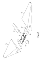
- FIG. 2 is a partially exploded view of the unmanned vehicle of FIG. 1 .
- FIG. 3 is a perspective view of an embodiment of a central platform according to the invention.
- FIG. 4 is a partially exploded view of the central platform of FIG. 3 .
- FIG. 5 is a partially assembled view of the unmanned vehicle of FIG. 1 .
- FIG. 6 is another partially assembled view of the unmanned vehicle of FIG. 1 .
- FIG. 7 is an embodiment of an MEUV aquatic configuration according to the present invention.
- FIG. 8 is an embodiment of an MEUV land configuration according to the present invention.
- FIG. 9 is an illustration of an embodiment of an MEUV system according to the invention.
- the Multiple Environment Unmanned Vehicle was developed to address the need for mobile robotic vehicles to traverse through more than a single type of environment.
- the MEUV is able to navigate aerial, aquatic, and terrestrial environments through the use of different mission mobility attachments.
- the attachments allow the MEUV to be deployed from greater distances either from the air or through the water prior to any terrestrial navigation that would be done by the terrestrial MEUV configuration.
- the mobility attachments can be removed or detached by the vehicle during a mission.
- the MEUV possesses the unique ability to be deployed in one environment and conduct a mission in a different environment.
- the MEUV may be deployed aerially to enter a desired area where the mission would then turn into ground surveillance.
- the MEUV is configured such that a chassis or central platform contains a control system or module containing the operational instructions, while various external accessories including mobility attachments are utilized dependent on the environment contained in the mission profile.
- FIGS. 1 and 2 illustrate an embodiment of an MEUV 10 according to the invention.
- the MEUV is shown in a MEUV flight or aerial configuration 10 A.
- the MEUV aerial configuration is an unmanned air vehicle (UAV) having a delta-wing configuration with controlled flight capability.
- UAV unmanned air vehicle
- the MEUV aerial configuration 10 A includes a chassis or central platform (platform) 12 , and wings 14 , a nose assembly 16 and a tail assembly 18 attached to the platform 12 . These components may be referred to as the MEUV aerial configuration kit.
- the wings 14 are pivotally attached to the platform 12 and can be pivoted or controlled by the platform 12 to control flight. This capability will be described in more detail below in discussing the platform 12 .
- the wings 14 form a delta-wing configuration.
- other wing geometries may be used.
- one or both of the wings 14 may be fixed or attached so to the platform 12 so as not to pivot, and the MEUV aerial configuration 10 A may be an uncontrolled glider.
- one or both of the wings 14 may be fixed to not pivot, and control of the MEUV aerial configuration 10 A may be performed by the tail assembly 18 or other flight control feature attached to and controlled by the platform 12 .
- the wings 14 include openings 15 .
- the nose and tail assemblies 14 , 16 provide aerodynamic stability and reduced drag to the MEUV aerial configuration 10 A.
- the tail assembly 18 is fixed to the platform 12 , however, in other embodiments, the tail assembly 18 may be controllably attached to the platform 12 to provide controlled flight.
- the tail assembly 18 may have additional and/or other geometries, such as, but not limited to vertical tail and other control surfaces to provide controlled flight to the MEUV 10 aerial configuration 10 A.
- the MEUV 10 and its components will be considered to have a front as indicated as towards line A and a rear as indicated as towards line B.
- the MEUV 10 further includes other mobility attachments, including control planes 20 , propulsion planes 22 , and wheels 24 that are internal to the MEUV aerial configuration 10 A.
- the control and propulsion planes 22 , 24 may be referred to as the aquatic kit.
- the wheels 24 may be referred to as the land kit.
- FIGS. 3 and 4 illustrate an embodiment of the platform 12 according to the invention.
- the platform 12 includes a housing 26 .
- the housing 26 includes a top panel 28 , a bottom (not shown), a front panel 30 , a rear panel 32 , a first side panel 34 , a second side panel 36 and drive unit housings 37 .
- the platform 12 also includes an optional first access panel 35 and an optional second access panel (not shown, positioned on the second side panel 36 ).
- the platform 12 may include one or more access panels. The panels are connected or joined by fasteners, such as, but not limited to screws, bolts and pins.
- the panels may be joined by fasteners, clips grooves, tabs or other fastening devices or methods as understood in the art.
- the platform 12 may include one or more panels.
- the platform 12 may include one or more panels that are connected and/or removable from one another.
- FIG. 4 illustrates a partially exploded view of the platform 12 having the top, front, bottom, rear and first side panel 28 , 30 , 32 , 34 removed.
- the platform 12 further includes a data/video radio unit 38 , a payload 42 , a power supply 43 , a drive system 44 and a control unit 46 . Note that wiring and other physical/electrical connections have been removed for clarity, but would be present as understood by one of ordinary skill in the art.
- the data/video radio unit 38 provides wireless communications and video transmission to and from the MEUV.
- the power supply 43 includes four batteries 48 .
- the platform 12 may include one or more control units and batteries.
- the control unit 40 and batteries 48 may be combined into a single unit.
- the batteries 48 are accessible by the first and second optional access panels 35 , (not shown).
- one or more control units and/or batteries may be accessed by one or more optional control panels.
- the control unit 46 includes a processor (not shown) capable of controlling MEUV functions, including, but not limited to movement planning, drive system control, navigation, payload control, communications, power systems, payloads.
- the control unit 46 may include a global positioning system, or Inertial Navigation System (INS) (not shown) and or other navigation aids to provide data for movement planning and navigation.
- INS Inertial Navigation System
- the control unit 46 is a single unit.
- the control unit 46 may include one or more units.
- the control unit or part thereof, such as a control unit module may be accessed by an access panel.
- the processor may include software and hardware including, but not limited to read-only-memory (RAM), solid state memory, and Field Programmable Gate Arrays (FPGAs) for controlling MEUV functions.
- RAM read-only-memory
- FPGAs Field Programmable Gate Arrays
- the control unit 46 also includes antennas 50 and a control/power input port 52 .
- the control unit 46 may include one or more antennas.
- the antennas 50 provide for data reception and transmission and video transmission.
- the control/power input port 52 provides connectivity to the control unit 40 and the batteries 48 .
- the connectivity to the control unit 46 may be used to provide control unit programming such as, but not limited to mission programming, navigation programming, communications programming, power supply, motion profiles, and payload profiles.
- the connectivity to the batteries 48 may be used to provide battery charging.
- the payload 42 is a camera.
- the camera 42 is capable of capturing still pictures and video images and providing those images to the control unit 46 .
- the camera 42 may be cable of capturing still pictures and/or video.
- the camera 42 may be capable of capturing, storing and/or transmitting images.
- the control unit 46 also includes a motion device 54 capable of tilting or directing the camera 42 .
- the motion control device 54 may be controlled by the camera 42 and/or by the control unit 46 .
- a motion device may be included in the payload 42 or may be omitted.
- the payload 42 may be a camera, sensor, explosive, additional processor and/or beacon.
- the sensor may be, but is not limited to a chemical sensor, radiation sensor, electromagnetic field sensor, pressure sensor, and spectrum analyzer.
- the drive system 44 includes four drive units 56 .
- Drive units 56 include an encoder 57 , motor 58 , gearbox 60 and output shaft 62 .
- the drive system 44 may include one or more drive units capable of powering two or more mobility devices.
- the drive system 44 is controlled by the control unit 46 .
- the drive system 44 may include hardware and/or software capable of providing control to the drive units 56 .
- the encoder provides the control system feedback on individual motor position.
- the motor 58 receives instructions from the control unit 46 and provides power to the gearbox 60 to rotate or drive the output shaft 62 .
- the drive system 44 provides 4 wheel independent drives.
- the drive system 44 may provide two or more wheel drive, i.e. a set of opposing wheels may be driven by the same drive system or one or more wheel may be driven by one or more drive systems.
- the MEUV 10 is assembled by collapsing the wheels 24 and attaching them to drive units 56 as shown in FIG. 5 .
- the wheels 24 do not collapse.
- the control and propulsion planes 20 , 22 are slipped over and attached to the wheels 24 as shown in FIG. 6 .
- the control and propulsion planes 20 , 22 are collapsed and fitted into openings 15 in wings 14 to arrive at the MEUV aerial configuration 10 A shown in FIG. 1 .
- the control and propulsion planes 20 , 22 do not collapse and fit into other appropriate openings in wings 14 .
- the MEUV 10 may be used or deployed by operating the MEUV aerial configuration 10 A ( FIG. 1 ) according to an assigned mission. Mission assignments and operation is discussed in further detail below.
- the wings 14 nose and tail assemblies 16 , 18 are separated from the MEUV 10 , and the MEUV 10 is now in an MEUV amphibious configuration 10 B as shown in FIG. 7 .
- the wings 14 , nose and tail assemblies 16 , 18 are separated, removed or jettisoned from the MEUV 10 by a mechanical release system (not shown).
- the wings 14 , nose and tail assemblies 16 , 18 may be separated from the MEUV 10 by mechanical, gas or other separation system and technique. For example, small explosives, airbags, and the use of dissolving materials may be used to separate the components.
- the MEUV 10 in an MEUV aerial configuration 10 B is an unpowered configuration.
- the MEUV 10 may be launched from another aerial vehicle or from a high platform, such as, but not limited to a building or terrestrial feature such as a hill or mountain.
- the MEUV 10 in an MEUV aerial configuration may be towed by a powered Unmanned Aerial Vehicle (UAV) to a predetermined point and then cut free to glide in covertly.
- UAV Unmanned Aerial Vehicle
- the MEUV may include a power unit including a propeller or rocket, for example included in the wings 14 , nose assembly 16 and/or tail assembly 18 .
- the MEUV may include the capacity to dump or separate the propulsion unit prior to entering a payload use zone.
- the MEUV 10 can be controlled in the MEUV aquatic configuration 10 B by pivoting or partially rotating the control planes 20 in a direction as shown by arrow A.
- the MEUV 10 may be controlled to dive or ascend in a fluid environment.
- the fluid environment may be, but is not limited to a water or sea environment.
- the MEUV 10 in the MEUV aquatic configuration 10 B may be propelled or moved through a fluid environment by cyclically pivoting or oscillating the propulsion planes 22 in a direction as shown by arrow A.
- the propulsion planes 22 will move up and down, much like a person using their feet to kick while swimming, to create a forward thrust.
- the MEUV 10 By oscillating one side faster than the other the MEUV 10 will be able to conduct turns that will change the MEUV heading.
- the MEUV 10 By controlling the angles of the control planes 22 the MEUV 10 will be able to dive, surface, and roll.
- the MEUV 10 has positive buoyancy in water, which acts as a failsafe so that if the vehicle encounters a problem or obstacle that it cannot overcome while operating underwater in autonomous mode, the vehicle will automatically resurface so that communications can be reestablished.
- control and propulsion planes 20 , 22 are separated from the MEUV 10 , and the MEUV 10 is now in an MEUV terrestrial or land configuration 10 C as shown in FIG. 8 .
- the control and propulsion planes 20 , 22 are separated, removed or jettisoned from the MEUV 10 by a mechanical release system (not shown).
- the control and propulsion planes 20 , 22 may be separated from the MEUV 10 by mechanical, gas or other separation system and technique. For example, small explosives, airbags, and the use of dissolving materials may be used to separate the components.
- the MEUV 10 in the MEUV land configuration 10 C can be driven or moved over a terrain by rotating or driving the wheels 20 in a direction indicated by arrow A.
- the MEUV 10 in the MEUV land configuration 10 C may be steered or turned by independently rotating or driving one or more wheels at a speed different from one or more of the other wheels.
- the MEUV land configuration 10 also provides for aquatic mode driving wherein the platform 12 is a sealed unit that has negative buoyancy, which causes the MEUV to sink to the bottom of a water environment. Operation in this state would mimic terrestrial or land navigation.
- a wheel is made up of several semi-circular molded flares that are spaced in order to allow the wheel to grip obstacles. Each individual flare acts as a leaf spring that can change its shape dramatically in order to absorb large bumps and shocks that the vehicle may encounter while navigating on land. Some scenarios that may require large energy absorption are tosses over a perimeter fence or into a second story window. In another embodiment, other wheel designs, such as, but not limited to solid wheels, inflated wheels, and tracks may be used.
- the MEUV may include two or more configurations selected from the aerial, amphibious and land configurations.
- the MEUV may be configured to include an aerial/amphibious/land, aerial/amphibious, aerial/land, and amphibious/land configuration.
- the wheels 20 would be contained or stored in wings 14 .
- the control and propulsion planes 20 , 22 would be connected to the drive units 56 .
- the ability for the MEUV to transition its operation between environments is rooted in the MEUV configurations.
- the MEUV can go through three different transitions, 1) Aerial to Aquatic, 2) Aerial to Terrestrial, and 3) Aquatic to Terrestrial.
- the manner in which the transition is carried can be mechanical and/or chemical.
- the transition may be performed by a mechanical release, air pressure assist, mechanical assist, the use of small explosives, airbags, to the use of dissolving materials.
- in a transition between the aerial and aquatic or land configurations may be chemically assisted, wherein the wings, portions of the wings, or adhesive attaching the wings to the platform and/or other mobility attachments may be made of a material that dissolves in water, thus allowing for the wings to be detached from the platform.
- an airbag in the transition from aerial mode to terrestrial mode, may be used to both absorb the energy of a crash landing, as well as to generate the force needed to remove the wings from the wheels.
- the aquatic to terrestrial transition could be carried out with the use of small charges oriented to blow the wheel coverings off, or by simply burning the casing that covers the wheels.
- FIG. 9 illustrates an embodiment of a MEUV system 64 according to the invention.
- the MEUV system 64 includes a MEUV 10 in a MEUV land configuration 10 C, a command center 66 , and a communications relay 68 .
- FIG. 9 shows the MEUV 10 in the MEUV land configuration
- the MEUV system 64 may be used to control the MEUV 10 in land, aquatic and/or aerial configuration.
- the MEUV 10 may be autonomous in one or more of the mission configurations.
- the control center 69 is capable of providing commands to and receiving data from the MEUV 10 while also in the MEUV aerial configuration 10 A and the MEUV aquatic configuration 10 B.
- the MEUV 10 may be provided data, such as, but not limited to waypoint, navigation correction, mission correction, and payload commands by the command center at any time before or during the MEUV mission.
- the MEUV 10 may perform all or part of its mission without the control center and communications relay 68 .
- the MEUV 10 may perform all or part of its mission without relaying data back to the command center and data from the MEUV 10 mission may be downloaded upon recovery.
- the command center 66 includes a user interface 70 and a communications system 72 .
- the user interface 70 includes a processor (not shown) and display 76 for operator control.
- the processor may include software, hardware and memory (not shown) for MEUV operations and control.
- the MEUV system 64 may include one or more command centers.
- the command center 66 communicates with the MUEV 10 via communications system 72 .
- the communications system 72 may include radio frequency (RF), microwave, optical or other communication architecture.
- the communications relay 68 is a tower.
- the communications relay may be on a satellite, aircraft, UAV, building, tower, structure or other object capable of providing line of site communications to the MEUV 10 .
- the MEUV system 64 may not include a communications relay.
- the MEUV system 64 may include one or more communications relays.
- a method for operating an MEUV includes programming an MUEV for a mission, deploying or launching the MEUV in an initial configuration selected for an MEUV aerial or aquatic configuration, transitioning the MEUV from either the aerial to aquatic or aquatic to land configurations, performing payload operations during the mission, optionally providing data to and receiving data from the MEUV during the mission, and optionally providing data to and receiving data from the MEUV after the mission.
- the MUEV can be commanded to reconfigure between aerial, aquatic, and land configurations by internal mission programming or upon a received message/transmission.
- the payload may be controlled and/or modified by internal mission programming and/or by a received message/transmission.
- mission planning such as, but not limited to waypoints and navigation, may be controlled and/or modified by internal programming and/or received message/transmission.
- the MEUV may be reconfigured autonomously, that is, by mechanisms and methods performed by the MEUV itself, and/or by operator assistance to remove one or more of the mobility attachments.
- the MEUV performs all of its reconfigurations including aerial to aquatic, aquatic to land and aerial to land, autonomously.
- the MEUV may perform one or more of its reconfigurations including aerial to aquatic, aquatic to land and aerial to land, with an operator's assistance. For example, and operator may remove the aerial mobility and/or aquatic mobility attachments at a time or waypoint during a mission.
Landscapes
- Engineering & Computer Science (AREA)
- Mechanical Engineering (AREA)
- Aviation & Aerospace Engineering (AREA)
- Transportation (AREA)
- Chemical & Material Sciences (AREA)
- Combustion & Propulsion (AREA)
- Remote Sensing (AREA)
- Control Of Position, Course, Altitude, Or Attitude Of Moving Bodies (AREA)
- Toys (AREA)
Abstract
Description
Claims (14)
Priority Applications (1)
| Application Number | Priority Date | Filing Date | Title |
|---|---|---|---|
| US15/422,252 US9844990B2 (en) | 2013-09-13 | 2017-02-01 | Multiple environment unmanned vehicle |
Applications Claiming Priority (3)
| Application Number | Priority Date | Filing Date | Title |
|---|---|---|---|
| US201361877829P | 2013-09-13 | 2013-09-13 | |
| US14/484,138 US9580172B2 (en) | 2013-09-13 | 2014-09-11 | Multiple environment unmanned vehicle |
| US15/422,252 US9844990B2 (en) | 2013-09-13 | 2017-02-01 | Multiple environment unmanned vehicle |
Related Parent Applications (1)
| Application Number | Title | Priority Date | Filing Date |
|---|---|---|---|
| US14/484,138 Continuation US9580172B2 (en) | 2013-09-13 | 2014-09-11 | Multiple environment unmanned vehicle |
Publications (2)
| Publication Number | Publication Date |
|---|---|
| US20170136840A1 US20170136840A1 (en) | 2017-05-18 |
| US9844990B2 true US9844990B2 (en) | 2017-12-19 |
Family
ID=54141362
Family Applications (2)
| Application Number | Title | Priority Date | Filing Date |
|---|---|---|---|
| US14/484,138 Active 2034-12-03 US9580172B2 (en) | 2013-09-13 | 2014-09-11 | Multiple environment unmanned vehicle |
| US15/422,252 Active US9844990B2 (en) | 2013-09-13 | 2017-02-01 | Multiple environment unmanned vehicle |
Family Applications Before (1)
| Application Number | Title | Priority Date | Filing Date |
|---|---|---|---|
| US14/484,138 Active 2034-12-03 US9580172B2 (en) | 2013-09-13 | 2014-09-11 | Multiple environment unmanned vehicle |
Country Status (2)
| Country | Link |
|---|---|
| US (2) | US9580172B2 (en) |
| WO (1) | WO2016039788A1 (en) |
Cited By (2)
| Publication number | Priority date | Publication date | Assignee | Title |
|---|---|---|---|---|
| US20180075760A1 (en) * | 2016-09-09 | 2018-03-15 | Wal-Mart Stores, Inc. | Solar rechargeable unmanned vehicle systems and methods to monitor a geographic area |
| US10633808B2 (en) | 2018-09-27 | 2020-04-28 | Eagle Technology, Llc | Robotic bridging system |
Families Citing this family (27)
| Publication number | Priority date | Publication date | Assignee | Title |
|---|---|---|---|---|
| US9621254B2 (en) * | 2012-09-21 | 2017-04-11 | Spatial Digital Systems, Inc. | Communications architectures via UAV |
| US20150367932A1 (en) * | 2013-10-05 | 2015-12-24 | Dillon Mehul Patel | Delta M-Wing Unmanned Aerial Vehicle |
| CN105874397A (en) * | 2014-11-28 | 2016-08-17 | 深圳市大疆创新科技有限公司 | Unmanned aerial vehicle and water sample detection method thereof |
| DE102014018857B4 (en) * | 2014-12-15 | 2017-10-05 | Alfred-Wegener-Institut Helmholtz-Zentrum für Polar- und Meeresforschung | Aerodynamically shaped, active towed body |
| US11467274B2 (en) | 2015-09-29 | 2022-10-11 | Tyco Fire & Security Gmbh | Search and rescue UAV system and method |
| US10162348B1 (en) * | 2016-02-04 | 2018-12-25 | United Services Automobile Association (Usaa) | Unmanned vehicle morphing |
| US10189566B2 (en) * | 2016-06-10 | 2019-01-29 | ETAK Systems, LLC | 3D coverage mapping of wireless networks with unmanned aerial vehicles |
| US9996082B2 (en) | 2016-06-14 | 2018-06-12 | The Boeing Company | Autonomous vehicle re-tasking during performance of a programmed task based on detection of a task interruption scenario |
| IL247772B (en) * | 2016-09-12 | 2022-05-01 | Israel Aerospace Ind Ltd | Modular vehicle system |
| CN106827989B (en) * | 2017-02-21 | 2019-03-29 | 荣成康派斯新能源车辆股份有限公司 | A kind of amphibious Multipurpose caravan compartment |
| CN109715497A (en) * | 2017-03-22 | 2019-05-03 | 极光飞行科学公司 | Multi rack structure Modularized unmanned machine system |
| US10737779B2 (en) * | 2017-08-18 | 2020-08-11 | The Johns Hopkins University | Vehicle control system for transitioning between mediums |
| WO2019079930A1 (en) * | 2017-10-23 | 2019-05-02 | 大连理工大学 | Sea-air-land-dive four-environment tilting three-rotor unmanned aerial vehicle capable of vertical take-off and landing |
| US10807013B2 (en) | 2017-12-20 | 2020-10-20 | Francis A. Alonso | Modified delta wing kite with inflatable fuselage |
| US11660920B2 (en) | 2018-02-28 | 2023-05-30 | Stmicroelectronics S.R.L. | Multi-environment flexible vehicle |
| US10661623B2 (en) * | 2018-03-01 | 2020-05-26 | The Government Of The United States Of America, As Represented By The Secretary Of The Navy | Multi-modal flying airplane and underwater glider |
| US11442190B2 (en) | 2018-04-16 | 2022-09-13 | Pgs Geophysical As | Autonomous marine survey nodes |
| US11619757B2 (en) | 2018-04-16 | 2023-04-04 | Pgs Geophysical As | Modular system for deployment and retrieval of marine survey nodes |
| JP7020279B2 (en) * | 2018-04-27 | 2022-02-16 | 富士通株式会社 | Flyers and how to control them |
| CN108638773B (en) * | 2018-06-15 | 2021-05-07 | 南京理工大学 | Three-rotor wheel type amphibious robot |
| US11124283B1 (en) * | 2018-06-24 | 2021-09-21 | Adam Wade Kennedy | Wing in ground effect vehicle |
| USD873350S1 (en) * | 2018-08-23 | 2020-01-21 | Francis A. Alonso | Zig-zagged swept wing kite |
| USD875183S1 (en) * | 2018-08-23 | 2020-02-11 | Francis A. Alonso | Zig-zagged swept wing kite |
| USD874577S1 (en) * | 2018-08-23 | 2020-02-04 | Francis A. Alonso | Swept wing kite |
| USD874578S1 (en) * | 2018-08-23 | 2020-02-04 | Francis A. Alonso | Swept wing kite |
| CN110001985A (en) * | 2019-04-01 | 2019-07-12 | 苏州臻迪智能科技有限公司 | A kind of smart machine |
| EP3950510A4 (en) * | 2019-04-01 | 2023-05-17 | Powervision Tech (Suzhou) Ltd. | Intelligent device and switching method therefor |
Citations (50)
| Publication number | Priority date | Publication date | Assignee | Title |
|---|---|---|---|---|
| US2470783A (en) * | 1945-05-15 | 1949-05-24 | Vincent A Mead | Plane marker buoy |
| US2562491A (en) * | 1947-07-26 | 1951-07-31 | Theodore P Hall | Flying automobile |
| US2791867A (en) * | 1953-06-01 | 1957-05-14 | Wayne G Dasher | Toy flying car |
| US3029042A (en) * | 1958-01-23 | 1962-04-10 | Ogden L Martin | Land, water and air vehicle |
| US3605935A (en) * | 1970-01-06 | 1971-09-20 | Richard H Gilbert | Air surface rapid transit vehicle |
| US4579297A (en) * | 1983-05-11 | 1986-04-01 | Joseph N. Ayoola | Air, land and sea vehicle |
| US4899954A (en) * | 1988-05-11 | 1990-02-13 | Pruszenski Jr Anthony | Ground-air-water craft |
| US4913375A (en) * | 1988-08-09 | 1990-04-03 | Fitzpatrick Peter J | Vehicle for use on land, air, or water |
| US5082198A (en) * | 1990-02-12 | 1992-01-21 | Patel Navnit R | Recreational flying vehicle |
| US20020125367A1 (en) * | 2001-03-12 | 2002-09-12 | Killingsworth Norman Don | Combination fixed and rotating wing aircraft, land vehicle and water craft |
| US20020139894A1 (en) * | 2001-02-01 | 2002-10-03 | Sorensen Bradford T. | Roadable aircraft boat that flies in a wind of its own making |
| US6517026B1 (en) * | 2001-09-06 | 2003-02-11 | Leo Smith | Vertical take-off and landing vehicle for land, water and air transport |
| US20030173454A1 (en) * | 2002-03-14 | 2003-09-18 | Paul Brown | All terrain aircraft (ATA) |
| US20030218099A1 (en) * | 2001-12-07 | 2003-11-27 | Daniel Preston | Multimodal, deployable vehicle |
| US20040211862A1 (en) * | 2003-04-25 | 2004-10-28 | Elam Daryl B. | Unmanned aerial vehicle with integrated wing battery |
| US6848647B2 (en) * | 2002-11-04 | 2005-02-01 | Testing Technologies, Inc. | Methods of buoyant and/or semi-buoyant (basb) vehicles utilizing basb in conjunction with pressurized fluid stream jet (pjet) and variously shaped bodies, wings, outriggers, and propulsion/repulsion configurations |
| US6866224B2 (en) * | 2000-08-22 | 2005-03-15 | Tigerfish Aviation Pty Ltd. | Seaplane with retractable twin floats |
| US20050247819A1 (en) * | 2004-05-08 | 2005-11-10 | Anthony Caruso | Lightweight vehicle operable on land, water and in the air |
| US20060162638A1 (en) * | 2005-01-26 | 2006-07-27 | Boncodin Franz B | Multi-mission/purpose ground-effect craft derived from a common modular platform |
| US20070012817A1 (en) * | 2004-08-13 | 2007-01-18 | Parmley Daniel W Sr | Multi-medium vehicle systems |
| US20080001025A1 (en) * | 2006-06-05 | 2008-01-03 | Lockheed Martin Corporation | Amphibious Aircraft |
| US20080032571A1 (en) | 2006-08-02 | 2008-02-07 | Gregory Dudek | Amphibious robotic device |
| US20080251308A1 (en) * | 2005-08-24 | 2008-10-16 | Dezso Molnar | Ground Air Water Craft |
| US20090121071A1 (en) * | 2007-11-12 | 2009-05-14 | Pik Wan Chan | Flying wing boat |
| US7658346B2 (en) * | 2005-02-25 | 2010-02-09 | Honeywell International Inc. | Double ducted hovering air-vehicle |
| US20100193626A1 (en) | 2009-02-03 | 2010-08-05 | Honeywell International Inc. | Transforming unmanned aerial-to-ground vehicle |
| US20110046821A1 (en) | 2009-07-22 | 2011-02-24 | Grabowsky John F | Reconfigurable aircraft |
| US20110042507A1 (en) * | 2009-08-19 | 2011-02-24 | Seiford Sr Donald S | Convertible Vehicle For Road, Air, and Water Usage |
| US7946530B1 (en) * | 2005-06-13 | 2011-05-24 | Talmage Jr Robert N | Modular adaptive configured helicopter |
| US20110163197A1 (en) * | 2009-11-27 | 2011-07-07 | Rainer Farrag | Flight unit that can be coupled to a road vehicle having single-file seating |
| WO2011131733A2 (en) * | 2010-04-22 | 2011-10-27 | Desaulniers Jean-Marc Joseph | Vertical take-off and landing multimodal, multienvironment, gyropendular craft with compensatory propulsion and fluidic gradient collimation |
| WO2011149544A1 (en) | 2010-05-26 | 2011-12-01 | Aerovironment Inc. | Reconfigurable battery-operated vehicle system |
| US20110315806A1 (en) * | 2010-05-17 | 2011-12-29 | Piasecki John W | Modular and morphable air vehicle |
| US8167234B1 (en) * | 2010-03-21 | 2012-05-01 | Michael Moore | Insect-like micro air vehicle having perching, energy scavenging, crawling, and offensive payload capabilities |
| US20120168555A1 (en) * | 2009-07-29 | 2012-07-05 | Andrei Yurievich Shcherbakov | Autonomous stratospheric lighter-than-air aircraft and method for providing radio and optical communication, television broadcasting and monitoring |
| US20120292435A1 (en) * | 2010-08-12 | 2012-11-22 | Abe Karem | Multi-Role Aircraft with Interchangeable Mission Modules |
| US8342440B2 (en) * | 2009-12-10 | 2013-01-01 | Regents Of The University Of Minnesota | Miniature robotic vehicle with ground and flight capability |
| US20130068876A1 (en) * | 2011-09-16 | 2013-03-21 | Bogdan Radu | Flying Vehicle |
| US20130126666A1 (en) * | 2008-07-28 | 2013-05-23 | MARTIN CHRIST GEFRIERTROCKNUGSANLAGEN GmbH | Combined air, water and road vehicle |
| US8464816B2 (en) * | 2008-12-11 | 2013-06-18 | Carsaf, Llc | All-terrain hostile environment vehicle |
| US20140021291A1 (en) * | 2012-06-11 | 2014-01-23 | James W. Vetter | Multi-orientation, advanced vertical agility,variable-environment vehicle |
| US20140061362A1 (en) * | 2012-08-29 | 2014-03-06 | Draganfly Innovations Inc. | Vehicle with aerial and ground mobility |
| US20140231593A1 (en) * | 2010-08-12 | 2014-08-21 | Abe Karem | Multi-Role Aircraft With Interchangeable Mission Modules |
| US20150028150A1 (en) * | 2011-08-30 | 2015-01-29 | Aeromobil, S.R.O. | Transformation method of hybrid transportation vehicle for ground and air, and hybrid transportation vehicle itself |
| US9061558B2 (en) * | 2012-11-14 | 2015-06-23 | Illinois Institute Of Technology | Hybrid aerial and terrestrial vehicle |
| US20150203184A1 (en) * | 2014-01-17 | 2015-07-23 | Joseph Nilo Sarmiento | Sail-equipped amphibious aerostat or dirigible |
| US9145207B2 (en) * | 2011-03-29 | 2015-09-29 | Institut Superieur De L'aeronautique Et De L'espace | Remotely controlled micro/nanoscale aerial vehicle comprising a system for traveling on the ground, vertical takeoff, and landing |
| US20150274000A1 (en) * | 2014-03-31 | 2015-10-01 | Paha Designs,Llc | Low gravity all-surface vehicle |
| US9493235B2 (en) * | 2002-10-01 | 2016-11-15 | Dylan T X Zhou | Amphibious vertical takeoff and landing unmanned device |
| US20170029106A1 (en) * | 2015-07-28 | 2017-02-02 | Inventec Appliances (Pudong) Corporation | Unmanned vehicle |
-
2014
- 2014-09-11 US US14/484,138 patent/US9580172B2/en active Active
- 2014-12-08 WO PCT/US2014/069141 patent/WO2016039788A1/en active Application Filing
-
2017
- 2017-02-01 US US15/422,252 patent/US9844990B2/en active Active
Patent Citations (53)
| Publication number | Priority date | Publication date | Assignee | Title |
|---|---|---|---|---|
| US2470783A (en) * | 1945-05-15 | 1949-05-24 | Vincent A Mead | Plane marker buoy |
| US2562491A (en) * | 1947-07-26 | 1951-07-31 | Theodore P Hall | Flying automobile |
| US2791867A (en) * | 1953-06-01 | 1957-05-14 | Wayne G Dasher | Toy flying car |
| US3029042A (en) * | 1958-01-23 | 1962-04-10 | Ogden L Martin | Land, water and air vehicle |
| US3605935A (en) * | 1970-01-06 | 1971-09-20 | Richard H Gilbert | Air surface rapid transit vehicle |
| US4579297A (en) * | 1983-05-11 | 1986-04-01 | Joseph N. Ayoola | Air, land and sea vehicle |
| US4899954A (en) * | 1988-05-11 | 1990-02-13 | Pruszenski Jr Anthony | Ground-air-water craft |
| US4913375A (en) * | 1988-08-09 | 1990-04-03 | Fitzpatrick Peter J | Vehicle for use on land, air, or water |
| US5082198A (en) * | 1990-02-12 | 1992-01-21 | Patel Navnit R | Recreational flying vehicle |
| US6866224B2 (en) * | 2000-08-22 | 2005-03-15 | Tigerfish Aviation Pty Ltd. | Seaplane with retractable twin floats |
| US20020139894A1 (en) * | 2001-02-01 | 2002-10-03 | Sorensen Bradford T. | Roadable aircraft boat that flies in a wind of its own making |
| US20020125367A1 (en) * | 2001-03-12 | 2002-09-12 | Killingsworth Norman Don | Combination fixed and rotating wing aircraft, land vehicle and water craft |
| US6517026B1 (en) * | 2001-09-06 | 2003-02-11 | Leo Smith | Vertical take-off and landing vehicle for land, water and air transport |
| US20030218099A1 (en) * | 2001-12-07 | 2003-11-27 | Daniel Preston | Multimodal, deployable vehicle |
| US20030173454A1 (en) * | 2002-03-14 | 2003-09-18 | Paul Brown | All terrain aircraft (ATA) |
| US9493235B2 (en) * | 2002-10-01 | 2016-11-15 | Dylan T X Zhou | Amphibious vertical takeoff and landing unmanned device |
| US6848647B2 (en) * | 2002-11-04 | 2005-02-01 | Testing Technologies, Inc. | Methods of buoyant and/or semi-buoyant (basb) vehicles utilizing basb in conjunction with pressurized fluid stream jet (pjet) and variously shaped bodies, wings, outriggers, and propulsion/repulsion configurations |
| US20040211862A1 (en) * | 2003-04-25 | 2004-10-28 | Elam Daryl B. | Unmanned aerial vehicle with integrated wing battery |
| US20050247819A1 (en) * | 2004-05-08 | 2005-11-10 | Anthony Caruso | Lightweight vehicle operable on land, water and in the air |
| US20070012817A1 (en) * | 2004-08-13 | 2007-01-18 | Parmley Daniel W Sr | Multi-medium vehicle systems |
| US20060162638A1 (en) * | 2005-01-26 | 2006-07-27 | Boncodin Franz B | Multi-mission/purpose ground-effect craft derived from a common modular platform |
| US7658346B2 (en) * | 2005-02-25 | 2010-02-09 | Honeywell International Inc. | Double ducted hovering air-vehicle |
| US7946530B1 (en) * | 2005-06-13 | 2011-05-24 | Talmage Jr Robert N | Modular adaptive configured helicopter |
| US20080251308A1 (en) * | 2005-08-24 | 2008-10-16 | Dezso Molnar | Ground Air Water Craft |
| US20080001025A1 (en) * | 2006-06-05 | 2008-01-03 | Lockheed Martin Corporation | Amphibious Aircraft |
| US20080032571A1 (en) | 2006-08-02 | 2008-02-07 | Gregory Dudek | Amphibious robotic device |
| US20090121071A1 (en) * | 2007-11-12 | 2009-05-14 | Pik Wan Chan | Flying wing boat |
| US20130126666A1 (en) * | 2008-07-28 | 2013-05-23 | MARTIN CHRIST GEFRIERTROCKNUGSANLAGEN GmbH | Combined air, water and road vehicle |
| US8464816B2 (en) * | 2008-12-11 | 2013-06-18 | Carsaf, Llc | All-terrain hostile environment vehicle |
| US20100193626A1 (en) | 2009-02-03 | 2010-08-05 | Honeywell International Inc. | Transforming unmanned aerial-to-ground vehicle |
| US20110046821A1 (en) | 2009-07-22 | 2011-02-24 | Grabowsky John F | Reconfigurable aircraft |
| US20120168555A1 (en) * | 2009-07-29 | 2012-07-05 | Andrei Yurievich Shcherbakov | Autonomous stratospheric lighter-than-air aircraft and method for providing radio and optical communication, television broadcasting and monitoring |
| US20110042507A1 (en) * | 2009-08-19 | 2011-02-24 | Seiford Sr Donald S | Convertible Vehicle For Road, Air, and Water Usage |
| US20110163197A1 (en) * | 2009-11-27 | 2011-07-07 | Rainer Farrag | Flight unit that can be coupled to a road vehicle having single-file seating |
| US8342440B2 (en) * | 2009-12-10 | 2013-01-01 | Regents Of The University Of Minnesota | Miniature robotic vehicle with ground and flight capability |
| US8167234B1 (en) * | 2010-03-21 | 2012-05-01 | Michael Moore | Insect-like micro air vehicle having perching, energy scavenging, crawling, and offensive payload capabilities |
| WO2011131733A2 (en) * | 2010-04-22 | 2011-10-27 | Desaulniers Jean-Marc Joseph | Vertical take-off and landing multimodal, multienvironment, gyropendular craft with compensatory propulsion and fluidic gradient collimation |
| US20130206915A1 (en) * | 2010-04-22 | 2013-08-15 | Jean-Marc (Joseph) Desaulniers | Vertical take-off and landing multimodal, multienvironment, gyropendular craft with compensatory propulsion and fluidic gradient collimation |
| US20150217613A1 (en) * | 2010-05-17 | 2015-08-06 | Piasecki Aircraft Corporation | Modular and Morphable Air Vehicle |
| US20110315806A1 (en) * | 2010-05-17 | 2011-12-29 | Piasecki John W | Modular and morphable air vehicle |
| WO2011149544A1 (en) | 2010-05-26 | 2011-12-01 | Aerovironment Inc. | Reconfigurable battery-operated vehicle system |
| US20120292435A1 (en) * | 2010-08-12 | 2012-11-22 | Abe Karem | Multi-Role Aircraft with Interchangeable Mission Modules |
| US20140231593A1 (en) * | 2010-08-12 | 2014-08-21 | Abe Karem | Multi-Role Aircraft With Interchangeable Mission Modules |
| US9145207B2 (en) * | 2011-03-29 | 2015-09-29 | Institut Superieur De L'aeronautique Et De L'espace | Remotely controlled micro/nanoscale aerial vehicle comprising a system for traveling on the ground, vertical takeoff, and landing |
| US20150028150A1 (en) * | 2011-08-30 | 2015-01-29 | Aeromobil, S.R.O. | Transformation method of hybrid transportation vehicle for ground and air, and hybrid transportation vehicle itself |
| US20130068876A1 (en) * | 2011-09-16 | 2013-03-21 | Bogdan Radu | Flying Vehicle |
| US20140021291A1 (en) * | 2012-06-11 | 2014-01-23 | James W. Vetter | Multi-orientation, advanced vertical agility,variable-environment vehicle |
| US9315266B2 (en) * | 2012-06-11 | 2016-04-19 | James W Vetter | Multi-orientation, advanced vertical agility, variable-environment vehicle |
| US20140061362A1 (en) * | 2012-08-29 | 2014-03-06 | Draganfly Innovations Inc. | Vehicle with aerial and ground mobility |
| US9061558B2 (en) * | 2012-11-14 | 2015-06-23 | Illinois Institute Of Technology | Hybrid aerial and terrestrial vehicle |
| US20150203184A1 (en) * | 2014-01-17 | 2015-07-23 | Joseph Nilo Sarmiento | Sail-equipped amphibious aerostat or dirigible |
| US20150274000A1 (en) * | 2014-03-31 | 2015-10-01 | Paha Designs,Llc | Low gravity all-surface vehicle |
| US20170029106A1 (en) * | 2015-07-28 | 2017-02-02 | Inventec Appliances (Pudong) Corporation | Unmanned vehicle |
Non-Patent Citations (1)
| Title |
|---|
| International Search Report and Written Opinion dated Nov. 2, 2015, for PCT/US 14/69141 filed Dec. 8, 2014. |
Cited By (2)
| Publication number | Priority date | Publication date | Assignee | Title |
|---|---|---|---|---|
| US20180075760A1 (en) * | 2016-09-09 | 2018-03-15 | Wal-Mart Stores, Inc. | Solar rechargeable unmanned vehicle systems and methods to monitor a geographic area |
| US10633808B2 (en) | 2018-09-27 | 2020-04-28 | Eagle Technology, Llc | Robotic bridging system |
Also Published As
| Publication number | Publication date |
|---|---|
| WO2016039788A1 (en) | 2016-03-17 |
| US9580172B2 (en) | 2017-02-28 |
| US20150266576A1 (en) | 2015-09-24 |
| US20170136840A1 (en) | 2017-05-18 |
Similar Documents
| Publication | Publication Date | Title |
|---|---|---|
| US9844990B2 (en) | Multiple environment unmanned vehicle | |
| US11124298B2 (en) | Foldable UAV | |
| US11220170B2 (en) | Reconfigurable battery-operated vehicle system | |
| US9493235B2 (en) | Amphibious vertical takeoff and landing unmanned device | |
| US10155588B2 (en) | Reconfigurable battery-operated vehicle system | |
| US10618648B2 (en) | System of play platform for multi-mission application spanning any one or combination of domains or environments | |
| US20170073070A1 (en) | Amphibious vertical takeoff and landing unmanned device with artificial intelligence (AI) and method and system for managing a crisis environment and controlling one or more targets | |
| US20180044000A1 (en) | Ground movement system plugin for vtol uavs | |
| Jaimes et al. | An approach to surveillance an area using swarm of fixed wing and quad-rotor unmanned aerial vehicles UAV (s) | |
| Green et al. | Autonomous hovering of a fixed-wing micro air vehicle | |
| Green et al. | Autonomous landing for indoor flying robots using optic flow | |
| US20220097812A1 (en) | Hybrid aquatic unmanned aerial and submersible vehicle | |
| Yamauchi et al. | Griffon: a man‐portable hybrid UGV/UAV | |
| US11994876B2 (en) | In-flight UAV deployment and retrieval platform | |
| Hobart et al. | Multiple environment unmanned vehicle | |
| Rudakevych et al. | A man portable hybrid UAV/UGV system | |
| US20200307783A1 (en) | Compact Transformable Robot | |
| Suhadi et al. | Design and Control of a Ground-Aerial Dual Actuator Monocopter (G-ADAM) | |
| KR102487736B1 (en) | Cabin module and multi modular flight vehicle | |
| Fielding et al. | OzBot TM-haptic augmentation of a teleoperated robotic platform for search and rescue operations | |
| Mak et al. | Design and development of the micro aerial vehicles for search, tracking and reconnaissance (MAVSTAR) for MAV08 | |
| Green et al. | The integration of a multimodal mav and biomimetic sensing for autonomous flights in near-earth environments | |
| KRISHNAN et al. | INTEGRATED MICRO AIR VEHICLE SYSTEMS | |
| Cowling et al. | Fully Automated BMAV for Surveillance and Reconnaissance on the Move |
Legal Events
| Date | Code | Title | Description |
|---|---|---|---|
| AS | Assignment |
Owner name: SANDIA CORPORATION, NEW MEXICO Free format text: ASSIGNMENT OF ASSIGNORS INTEREST;ASSIGNORS:HOBART, CLINTON G.;MORSE, WILLIAM D.;BICKERSTAFF, ROBERT JAMES;SIGNING DATES FROM 20141006 TO 20141215;REEL/FRAME:044123/0129 Owner name: NATIONAL TECHNOLOGY & ENGINEERING SOLUTIONS OF SAN Free format text: CHANGE OF NAME;ASSIGNOR:SANDIA CORPORATION;REEL/FRAME:044444/0054 Effective date: 20170501 |
|
| STCF | Information on status: patent grant |
Free format text: PATENTED CASE |
|
| MAFP | Maintenance fee payment |
Free format text: PAYMENT OF MAINTENANCE FEE, 4TH YEAR, LARGE ENTITY (ORIGINAL EVENT CODE: M1551); ENTITY STATUS OF PATENT OWNER: LARGE ENTITY Year of fee payment: 4 |