US9844745B2 - Controlled pulse air filter system - Google Patents
Controlled pulse air filter system Download PDFInfo
- Publication number
- US9844745B2 US9844745B2 US15/291,362 US201615291362A US9844745B2 US 9844745 B2 US9844745 B2 US 9844745B2 US 201615291362 A US201615291362 A US 201615291362A US 9844745 B2 US9844745 B2 US 9844745B2
- Authority
- US
- United States
- Prior art keywords
- filter
- injector
- neighboring
- air
- injectors
- Prior art date
- Legal status (The legal status is an assumption and is not a legal conclusion. Google has not performed a legal analysis and makes no representation as to the accuracy of the status listed.)
- Expired - Fee Related
Links
Images


Classifications
-
- B01D46/0068—
-
- B01D46/002—
-
- B—PERFORMING OPERATIONS; TRANSPORTING
- B01—PHYSICAL OR CHEMICAL PROCESSES OR APPARATUS IN GENERAL
- B01D—SEPARATION
- B01D46/00—Filters or filtering processes specially modified for separating dispersed particles from gases or vapours
- B01D46/24—Particle separators, e.g. dust precipitators, using rigid hollow filter bodies
- B01D46/2403—Particle separators, e.g. dust precipitators, using rigid hollow filter bodies characterised by the physical shape or structure of the filtering element
- B01D46/2411—Filter cartridges
-
- B—PERFORMING OPERATIONS; TRANSPORTING
- B01—PHYSICAL OR CHEMICAL PROCESSES OR APPARATUS IN GENERAL
- B01D—SEPARATION
- B01D46/00—Filters or filtering processes specially modified for separating dispersed particles from gases or vapours
- B01D46/56—Filters or filtering processes specially modified for separating dispersed particles from gases or vapours with multiple filtering elements, characterised by their mutual disposition
- B01D46/58—Filters or filtering processes specially modified for separating dispersed particles from gases or vapours with multiple filtering elements, characterised by their mutual disposition connected in parallel
-
- B—PERFORMING OPERATIONS; TRANSPORTING
- B01—PHYSICAL OR CHEMICAL PROCESSES OR APPARATUS IN GENERAL
- B01D—SEPARATION
- B01D46/00—Filters or filtering processes specially modified for separating dispersed particles from gases or vapours
- B01D46/66—Regeneration of the filtering material or filter elements inside the filter
- B01D46/70—Regeneration of the filtering material or filter elements inside the filter by acting counter-currently on the filtering surface, e.g. by flushing on the non-cake side of the filter
- B01D46/71—Regeneration of the filtering material or filter elements inside the filter by acting counter-currently on the filtering surface, e.g. by flushing on the non-cake side of the filter with pressurised gas, e.g. pulsed air
-
- B—PERFORMING OPERATIONS; TRANSPORTING
- B01—PHYSICAL OR CHEMICAL PROCESSES OR APPARATUS IN GENERAL
- B01D—SEPARATION
- B01D2267/00—Multiple filter elements specially adapted for separating dispersed particles from gases or vapours
- B01D2267/30—Same type of filters
Definitions
- This invention relates generally to air filtering systems and, more particularly, to a controlled pulse air filtering system.
- a method for self-cleaning the filters of such an air filtering system is also described and claimed herein.
- Air filtering units are commonly used in manufacturing processes.
- One typical application is to clean the air within a welding station.
- a conduit is connected between an opening in the welding station and the air filtering unit.
- the air within the welding station is drawn from the welding station, through the conduit and into the filtering unit by a blower fan.
- a plurality of filters are mounted in the filtering unit and the air from the welding station is pulled through the filters. the filters extract the particulate from the air and then the air is expelled from the filter unit back into the surrounding environment.
- air injectors are traditionally positioned adjacent to each of the filters.
- the air injectors are supplied with compressed air. All of the air injectors are simultaneously actuated forcing compressed air into and through the filters, from the inside to the outside, for the purpose of discharging any particulates that have accumulated on the filters.
- the compressed air released from the air injectors and gravity directs the discharged particulates into a collector unit disposed below the filters.
- a large amount of the particulate that has accumulated on the filters can be forced out of the filters.
- the unit operational i.e.
- the controlled pulse of the present invention overcomes this problem of the discharged particulate being drawn back onto the filters during cleaning operations when the filter unit is operational.
- this invention provides an improved method for cleaning the filters of an air filtering unit while the unit is operational.
- the method of the present invention includes providing a plurality of air filters and providing a plurality of compressed air injectors adjacent the air filters.
- a first injector is activated to force compressed air into a first filter. This discharges particulate from the first filter.
- the first injector is immediately deactivated and re-activated.
- the injectors directly adjacent the first injector are also activated. This step is performed while the discharged particulate is airborne to shield the first filter and force at least a portion of the discharged particulate away from the first filter and the adjacent filters.
- the operation is performed on each of the remaining filters.
- a self-cleaning air filtering system includes a programmable logic controller operably connected to compressed air injectors to actuate the injectors.
- the programmable logic controller is programmed with executable instructions defined by the steps of the inventive method described above. Accordingly, the executable instructions of the programmable logic controller include activating a first injector to force compressed air into the first filter and discharge particulate from the first filter. The first injector is deactivated for a short time and then the first injector is reactivated along with injectors directly adjacent the first injector.
- the programmable logic controller is programmed to repeat the executable instructions for each of the air filters in the system.
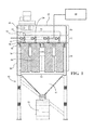
- FIG. 1 is a front cutaway view of the controlled pulse air filter system of the present invention
- FIG. 2 is a side partial cutaway view of the controlled pulse air filter system of the present invention.
- FIG. 3 is a top cutaway view of the controlled pulse airfiltering system showing the plurality of compressed air injectors of the present invention.
- the method is performed by initially providing an air filtering system 20 .
- the disclosed air filtering system 20 includes a plurality of air filters 22 serviced by a plurality of compressed air injectors 24 . While the plurality of air filters 22 may be arranged in a variety of configuration in accordance with the invention, it is envisioned that the filters 22 may be disposed in side-by-side spaced relationship. Similarly, each filter 22 in the plurality of air filters 22 may take a variety of shapes and configurations without departing from the scope of this invention. For example, each air filter 22 may include a filter material 26 of an elongated cylindrical shape surrounding a hollow core.
- the filters 22 may be spaced apart from one another by a predetermined distance d extending linearly between the filter material 26 of adjacent filters 22 .
- the predetermined distance d may be the smallest distance that can be measured between adjacent filters 22 arranged in side-by-side spaced relationship.
- the plurality of air filters 22 include a first filter 28 and at least one neighboring filter 30 adjacent the first filter 28 .
- the plurality of compressed air injectors 24 include a first injector 32 and at least one neighboring injector 34 adjacent the first injector 32 . It should be appreciated that the first injector 32 is disposed adjacent the first filter 28 and that each neighboring injector 34 is disposed adjacent the corresponding neighboring filter 30 .
- a compressed air supply 36 is provided in fluid communication with the compressed air injectors 24 to supply the injectors 24 with a source of compressed air.
- each of the compressed air injectors 24 may be aimed such as to provide a pulse of compressed air into the hollow core of the filters 22 .
- the pulse of compressed air into the hollow core of the filters 22 discharges particulate that has accumulated on the filter material 26 by introducing a shockwave of air into the filter 22 . It is further believed that this shockwave functions to expand folded pleats of the filter material 26 thereby releasing dirt that has accumulated on the filter 22 .
- the plurality of air filters 22 may be provided within a housing 38 .
- a blower fan 40 maybe provided in fluid communication with the housing 38 to facilitate the flow of air through the filters 22 .
- the housing 38 may take a variety of forms, the housing 38 may be generally rectangular in shape.
- the housing 38 may also be provided with a collector unit 42 in fluid communication with the filters 22 .
- the collector unit 42 may collect and trap particulate disposed within the housing 38 .
- the collector unit 42 may take the form of a frustoconcial shape extending downwardly from the housing.
- the collector unit 42 or a trap 44 attached thereto, may be removably attached to the housing 38 for ease of cleaning.
- the housing 38 may define an inlet 46 for receiving a volume of air to be filtered.
- the housing 38 may further define an outlet 48 for discharging a volume of filtered air after it has passed through the filters 22 .
- the method includes a series of steps wherein the compressed air injectors 24 are actuated to deliver a series of controlled pulses of compressed air to the plurality of air filters 22 .
- the method includes the step of activating the first injector 32 for a first time duration to force compressed air into the first filter 28 and discharge particulate from the first filter 28 . This step is referred to herein as the activating step. It should be appreciated that during the activating step, the first injector 32 is activated while the at least one neighboring injector 34 remains deactivated.
- the method proceeds with the step of deactivating the first injector 32 for a second time duration. This step is referred to herein as the deactivating step.
- the second time duration of the deactivating step may be shorter than the first time duration of the activating step.
- the first injector 32 may be deactivated for only a brief moment. More specifically, the second time duration of the deactivating step is less than a time required for the discharged particulate to travel the predetermined distance d between the first filter 28 and the neighboring filter 30 or neighboring filters 30 . This allows enough time for the particulate to leave the first filter 28 but does not present enough time for the particulate to migrate across the predetermined distance d to become entrained on the at least one neighboring filter 30 .
- the method further includes the step of reactivating the first injector 32 and simultaneously activating the at least one neighboring injector 34 for a third time duration.
- This step is referred to herein as the reactivating step.
- the reactivating step includes both the reactivation of the first injector 32 and the simultaneously activation of the at least one neighboring injector 34 .
- the third time duration of the reactivating step may be longer than the first time duration of the activating step.
- the first injector 32 and the at least one neighboring injector 34 provide simultaneous pulses of compressed air while the discharged particulate is airborne and force at least a portion of the discharged particulate away from the first filter 28 and the at least one neighboring filter 30 , directing the discharged particulate towards the collector unit 42 .
- the reactivating step provides an air shield about the first filter 28 that prevents the first filter 28 and the at least one neighboring filter 30 from entrapping or re-entrapping the discharged particulate when it is airborne as a result of the activation of the first injector 32 during the activation step.
- the pressure of the compressed air may differ between the activating and reactivating step.
- the activating step of activating the first injector 32 to force compressed air into the first filter 28 and discharge articulate from the first filter 28 may further include supplying a first pressure pulse to the first filter 28 .
- the reactivating step of reactivating the first injector 32 and activating the at least one neighboring injector 34 simultaneously following the deactivation of the first injector 32 and while the discharged particulate is airborne may further include supplying a second pressure pulse simultaneously to the first filter 28 and the at least one neighboring filter 30 wherein the first pressure pulse is greater than the second pressure pulse.
- the first pressure pulse of the activating step may be of a higher or greater positive pressure than that of the second pressure pulse of the reactivating step.
- the filter 22 being designated as the first filter 28 will change with each iteration of the method until all of the filters 22 have been cleaned by the controlled pulses of compressed air.
- the subject method may be employed during operation of the air filtering system 20 .
- the method of delivering the controlled pulses of compressed air to the filters 22 may be performed while air is being communicated through the filters 22 .
- the method steps recited above may all be performed while the blower fan 40 is running to draw air through the filters 22 .
- the subject method may be performed while the air filtering system 20 is not in operation.
- FIG. 3 illustrates an exemplary air filter system 20 of the subject invention having a total of twelve filters 22 and twelve injectors 24 a - 1 .
- injector 24 a may be designated as the first injector 32 and injectors 24 b , 24 f , and 24 e may be designated as the neighboring injectors 34 observing that injectors 24 b , 24 f , and 24 e are directly adjacent injector 24 a .
- the first injector 24 a is activated while the neighboring injectors 24 b , 24 f , and 24 e remain deactivated.
- the first injector 24 a is deactivated.
- the first injector 24 a is reactivated and, at the same time, the neighboring injectors 24 b , 24 f , and 24 e are activated to shield the filters 22 from the discharged particulate as it is travels to the collector unit 42 .
- This cleaning methodology may then be repeated for each of the filters 22 and repeats itself for as long as the air filter system 20 is in operation.
- the method may continue with a second exemplary iteration wherein injector 24 b is designated as the first injector 32 and injectors 24 a , 24 f , and 24 c are designated as the neighboring injectors 34 observing that injectors 24 a , 24 f , and 24 c are directly adjacent injector 24 b .
- injector 24 b is activated while the neighboring injectors 24 a , 24 f , and 24 c remain deactivated.
- the first injector 24 b is deactivated.
- the first injector 24 b is reactivated and, at the same time, the neighboring injectors 24 a , 24 f , and 24 c are activated. It should be appreciated that in the second exemplary iteration, the plurality of neighboring injectors 34 could be expanded to further include injectors 24 e and 24 g.
- injector 24 f is designated as the first injector 32 and injectors 24 b , 24 e , 24 j , and 24 g are designated as the neighboring injectors 34 observing that injectors 24 b , 24 e , 24 j , and 24 g are directly adjacent injector 24 f .
- the first injector 24 f is activated while the neighboring injectors 24 b , 24 e , 24 j , and 24 g remain deactivated.
- the first injector 24 f is deactivated.
- the first injector 24 f is reactivated and, at the same time, the neighboring injectors 24 b , 24 e , 24 j , and 24 g are activated.
- the plurality of neighboring injectors 34 could be expanded to further include injectors 24 a , 24 i , 24 k and 24 c.
- the air filtering system 20 has a housing 38 including an inlet 46 and an outlet 48 .
- the housing 38 may be divided into several plenums including a first plenum 50 , a second plenum 52 , and a third plenum 54 each being partially separated from one another by a plurality of dividers 56 .
- the first plenum 50 also referred to as the dirty air plenum, is adjacent the inlet 46 and receives a volume of air from the inlet 46 to be filtered.
- the inlet 46 may be in fluid communication with a welding station.
- the first plenum 50 houses a plurality of air filters 22 including a first filter 28 and at least one neighboring filter 30 adjacent the first filter 30 .
- the plurality of air filters 22 may be disposed in side-by-side spaced relationship and each air filter 22 includes a filter material 26 of an elongated cylindrical shape surrounding a hollow core.
- the plurality of air filters 22 may be mounted to the divider 56 partially separating the first plenum 50 and the second plenum 52 . Additionally, this divider 56 may include a plurality of holes that are radially aligned with the hollow core of each filter 22 through which air may travel from the first plenum 50 to the second plenum 52 .
- the second plenum 52 also referred to as the air tank plenum, is disposed between the first plenum 50 and the third plenum 54 .
- the second plenum 52 may house a plurality of compressed air injectors 24 adjacent to the air filters 22 including a first air injector 32 adjacent the first filter 28 and at least one neighboring injector 34 adjacent each neighboring filter 30 .
- the air injectors 24 are positioned to force compressed air into the hollow core of the air filters 22 and each injector 24 may further include a nozzle 58 configured to diffuse the air pulse provided by the injector 24 over a larger area.
- a compressed air supply 36 is provided in fluid communication with the compressed air injectors 24 to supply the injectors 24 with compressed air.
- the compressed air supply 36 could be a tank of compressed air or an air compressor. Further, the compressed air supply 36 may be part of the air filtering system 20 , a standalone unit, or a compressed air line common in many factories or plants. As such, the capacity of the compressed air supply 36 may be limited such that the pressure provided to the injectors 24 may vary depending on the frequency with which the injectors 24 are activated.
- the divider 56 partially separating the second plenum 52 and the third plenum 54 may include a plurality of venturi openings 60 through which air may travel from the second plenum 52 to the third plenum 54 .
- the third plenum 54 is adjacent the outlet 48 which discharges the filtered air.
- the third plenum 54 may house a blower fan 40 for drawing air through the air filtering system 20 .
- the first plenum 50 and second plenum 52 may operate in a negative pressure environment while the third plenum 54 may operate in a positive pressure environment.
- the negative pressure environment of the first plenum 50 and second plenum 52 facilitates drawing dirty air in through inlet 46 and through the filters 22 from outside the filter material 26 to inside the hollow core.
- the positive pressure environment of the third plenum 54 facilitates expelling filtered air out through the outlet 48 .
- an exemplary flow path of air through the air filtering system 20 is as follows. Air is drawn in through the inlet 46 and received in the first plenum 50 . The air is pulled through the filters 22 from outside the filter material 26 and into the hollow core of the filters 22 . The air passes from the hollow core of the filters 22 , through the holes in the divider 56 separating the first plenum 50 and the second plenum 52 , and into the second plenum 52 . The air then travel from the second plenum 52 to the third plenum 54 through the venturi openings 60 . Once in the third plenum 54 , the air is expelled through the outlet 48 .
- a collector unit 42 is disposed in fluid communication with the filters 22 for collecting and trapping particulate. More particularly, the collector unit 42 may be connected to the housing 38 adjacent the first plenum 50 . Both the air pulses from the injectors 24 and gravity may facilitate the passage of particulate from the filters 22 to the collector unit 42 .
- the collector unit 42 may have upwardly sloping sides or may have a frustoconical shape.
- a trap 44 may be removably connected to the collector unit 42 for receiving the particulate.
- the trap 44 may generally be barrel shaped and disposed beneath the collector unit 42 . As such, the trap 44 can be disconnected and cleaned. Alternatively, the trap 44 may be in the form of a tray that may be slid out from the collector unit 42 and cleaned.
- the air filtering system 20 may be supported by a frame 62 .
- the frame 62 may be attached to the collector unit 42 and/or the housing 38 .
- the air filtering system 20 further includes a programmable logic controller 64 electrically connected to the compressed air injectors 24 .
- the programmable logic controller 64 is programmed with executable instructions including activating the first air injector 32 for a first time duration to force compressed air into the first filter 28 . This discharges particulate from the first filter 28 , rendering it airborne outside the filter material 26 of the first filter 28 and within the first plenum 50 .
- the executable instructions also include deactivating the first air injector 32 for a second time duration being shorter than the first time duration and reactivating the first air injector 32 and simultaneously activating the at least one neighboring injector 34 for a third time duration being longer than the first time duration.
- the first injector 32 is reactivated and the at least one neighboring injector 34 is simultaneously activated while the discharged particulate is airborne to provide an air shield about the first filter 28 and force at least a portion of the discharged particulate away from the first filter 28 and the at least one neighboring filter 30 and towards the collector unit 42 .
- the programmable logic controller 64 further provides for repeating the executable instructions for each of the air filters 22 .
Landscapes
- Chemical & Material Sciences (AREA)
- Chemical Kinetics & Catalysis (AREA)
- Physics & Mathematics (AREA)
- Geometry (AREA)
- Filtering Of Dispersed Particles In Gases (AREA)
Abstract
Description
Claims (16)
Priority Applications (2)
| Application Number | Priority Date | Filing Date | Title |
|---|---|---|---|
| US15/291,362 US9844745B2 (en) | 2012-09-18 | 2016-10-12 | Controlled pulse air filter system |
| US15/843,226 US20180104634A1 (en) | 2012-09-18 | 2017-12-15 | Controlled air pulse air filter system |
Applications Claiming Priority (3)
| Application Number | Priority Date | Filing Date | Title |
|---|---|---|---|
| US201261702378P | 2012-09-18 | 2012-09-18 | |
| US13/769,641 US9468879B2 (en) | 2012-09-18 | 2013-02-18 | Controlled pulse air filter system |
| US15/291,362 US9844745B2 (en) | 2012-09-18 | 2016-10-12 | Controlled pulse air filter system |
Related Parent Applications (1)
| Application Number | Title | Priority Date | Filing Date |
|---|---|---|---|
| US13/769,641 Division US9468879B2 (en) | 2012-09-18 | 2013-02-18 | Controlled pulse air filter system |
Related Child Applications (1)
| Application Number | Title | Priority Date | Filing Date |
|---|---|---|---|
| US15/843,226 Division US20180104634A1 (en) | 2012-09-18 | 2017-12-15 | Controlled air pulse air filter system |
Publications (2)
| Publication Number | Publication Date |
|---|---|
| US20170028332A1 US20170028332A1 (en) | 2017-02-02 |
| US9844745B2 true US9844745B2 (en) | 2017-12-19 |
Family
ID=50273101
Family Applications (3)
| Application Number | Title | Priority Date | Filing Date |
|---|---|---|---|
| US13/769,641 Expired - Fee Related US9468879B2 (en) | 2012-09-18 | 2013-02-18 | Controlled pulse air filter system |
| US15/291,362 Expired - Fee Related US9844745B2 (en) | 2012-09-18 | 2016-10-12 | Controlled pulse air filter system |
| US15/843,226 Abandoned US20180104634A1 (en) | 2012-09-18 | 2017-12-15 | Controlled air pulse air filter system |
Family Applications Before (1)
| Application Number | Title | Priority Date | Filing Date |
|---|---|---|---|
| US13/769,641 Expired - Fee Related US9468879B2 (en) | 2012-09-18 | 2013-02-18 | Controlled pulse air filter system |
Family Applications After (1)
| Application Number | Title | Priority Date | Filing Date |
|---|---|---|---|
| US15/843,226 Abandoned US20180104634A1 (en) | 2012-09-18 | 2017-12-15 | Controlled air pulse air filter system |
Country Status (1)
| Country | Link |
|---|---|
| US (3) | US9468879B2 (en) |
Families Citing this family (2)
| Publication number | Priority date | Publication date | Assignee | Title |
|---|---|---|---|---|
| US20160114279A1 (en) * | 2013-07-13 | 2016-04-28 | Gerhard Kemper | Filter apparatus for extracting fine dust from air |
| CN114210164B (en) * | 2021-12-06 | 2023-05-05 | 莱芜钢铁集团泰东实业有限公司 | Dust fall device for steel slag grinding workshop |
Citations (4)
| Publication number | Priority date | Publication date | Assignee | Title |
|---|---|---|---|---|
| US3954426A (en) * | 1973-02-26 | 1976-05-04 | Inoma Filter Ab | Method for cleaning a dust filter |
| US5616171A (en) * | 1994-01-07 | 1997-04-01 | Donaldson Company, Inc. | Pulse jet filter cleaning system |
| US6270732B1 (en) * | 1998-06-30 | 2001-08-07 | Nanogram Corporation | Particle collection apparatus and associated methods |
| US20020073849A1 (en) * | 2000-09-05 | 2002-06-20 | Buettner John M. | Bag house elements |
Family Cites Families (3)
| Publication number | Priority date | Publication date | Assignee | Title |
|---|---|---|---|---|
| CH625969A5 (en) * | 1977-07-15 | 1981-10-30 | Buehler Ag Geb | |
| US4504293A (en) * | 1980-11-06 | 1985-03-12 | Donaldson Company, Inc. | Self-cleaning air filter |
| US8460443B2 (en) * | 2008-10-27 | 2013-06-11 | Jet Flow Dynamics, LLC | Portable dust collector |
-
2013
- 2013-02-18 US US13/769,641 patent/US9468879B2/en not_active Expired - Fee Related
-
2016
- 2016-10-12 US US15/291,362 patent/US9844745B2/en not_active Expired - Fee Related
-
2017
- 2017-12-15 US US15/843,226 patent/US20180104634A1/en not_active Abandoned
Patent Citations (4)
| Publication number | Priority date | Publication date | Assignee | Title |
|---|---|---|---|---|
| US3954426A (en) * | 1973-02-26 | 1976-05-04 | Inoma Filter Ab | Method for cleaning a dust filter |
| US5616171A (en) * | 1994-01-07 | 1997-04-01 | Donaldson Company, Inc. | Pulse jet filter cleaning system |
| US6270732B1 (en) * | 1998-06-30 | 2001-08-07 | Nanogram Corporation | Particle collection apparatus and associated methods |
| US20020073849A1 (en) * | 2000-09-05 | 2002-06-20 | Buettner John M. | Bag house elements |
Also Published As
| Publication number | Publication date |
|---|---|
| US20180104634A1 (en) | 2018-04-19 |
| US9468879B2 (en) | 2016-10-18 |
| US20140076160A1 (en) | 2014-03-20 |
| US20170028332A1 (en) | 2017-02-02 |
Similar Documents
| Publication | Publication Date | Title |
|---|---|---|
| US4331459A (en) | Self-cleaning pulsed air cleaner | |
| US4364751A (en) | Self-cleaning pulsed air cleaner | |
| US8349057B2 (en) | Method for the backflushing of filters | |
| CN101905105B (en) | Dust collecting apparatus | |
| CN105169836B (en) | Filter cleaning system | |
| USRE32185E (en) | Self-cleaning pulsed air cleaner | |
| US10272378B2 (en) | Filter device and method for cleaning at least one filter element, in particular by using such a filter device | |
| KR102304182B1 (en) | Device for recycling charcoal fire | |
| CN102300649A (en) | Portable Devices For Touchless Particulate Matter Removal | |
| CN101239343A (en) | Injector for bag filter of dust collector | |
| KR20190081124A (en) | Bag filter pulse control system | |
| KR101498162B1 (en) | Dust cleaner cyclone-type auto dust collecting device using ejector | |
| WO2019085212A1 (en) | Kitchen smoke processing device and cooking system | |
| US9844745B2 (en) | Controlled pulse air filter system | |
| US11724227B2 (en) | Pulse air cleaner system and methods with controlled scavenge | |
| KR101416563B1 (en) | Air purification equipment | |
| JP6702650B2 (en) | Fibrous filter system and method for cleaning the fibrous filter system | |
| KR101329020B1 (en) | Dust collecting device | |
| CN204502615U (en) | A kind of deduster fold shape filter bag | |
| KR101236503B1 (en) | Air purification equipment | |
| KR20150133453A (en) | cartridge filter with double mash | |
| AU762635B2 (en) | Dust filter | |
| KR100845958B1 (en) | Filter fixing structure of dust collector | |
| EP1838406B1 (en) | Pleated air filter with reverse pulsating air flow cleaning | |
| US20050252178A1 (en) | Dual jet cleaning system for dust filter assembly |
Legal Events
| Date | Code | Title | Description |
|---|---|---|---|
| AS | Assignment |
Owner name: ROBOVENT PRODUCTS GROUP, INC., MICHIGAN Free format text: ASSIGNMENT OF ASSIGNORS INTEREST;ASSIGNOR:REID, JOHN;REEL/FRAME:040069/0737 Effective date: 20161019 |
|
| STCF | Information on status: patent grant |
Free format text: PATENTED CASE |
|
| AS | Assignment |
Owner name: TWIN BROOK CAPITAL PARTNERS, LLC, AS AGENT, ILLINO Free format text: SECURITY INTEREST;ASSIGNORS:ROBOVENT PRODUCTS GROUP, INC.;PERMATRON CORPORATION;REEL/FRAME:044796/0861 Effective date: 20180131 |
|
| AS | Assignment |
Owner name: TWIN BROOK CAPITAL PARTNERS, LLC, AS AGENT, ILLINO Free format text: CORRECTIVE ASSIGNMENT TO CORRECT THE APPLICATION NUMBER PREVIOUSLY RECORDED AT REEL: 044796 FRAME: 0861. ASSIGNOR(S) HEREBY CONFIRMS THE SECURITY INTEREST;ASSIGNORS:ROBOVENT PRODUCTS GROUP, INC.;PERMATRON CORPORATION;REEL/FRAME:045455/0595 Effective date: 20180131 |
|
| AS | Assignment |
Owner name: BMO HARRIS BANK N.A., ILLINOIS Free format text: INTELLECTUAL PROPERTY SECURITY AGREEMENT;ASSIGNORS:ROBOVENT PRODUCTS GROUP, INC.;ROBOVENT ACQUISITION, INC.;VISKON-AIRE CORPORATION;AND OTHERS;REEL/FRAME:054514/0490 Effective date: 20201124 |
|
| AS | Assignment |
Owner name: ROBOVENT PRODUCTS GROUP, INC., MICHIGAN Free format text: RELEASE BY SECURED PARTY;ASSIGNOR:TWIN BROOK CAPITAL PARTNERS, LLC, AS AGENT;REEL/FRAME:054495/0947 Effective date: 20201124 Owner name: PERMATRON CORPORATION, ILLINOIS Free format text: RELEASE BY SECURED PARTY;ASSIGNOR:TWIN BROOK CAPITAL PARTNERS, LLC, AS AGENT;REEL/FRAME:054495/0947 Effective date: 20201124 |
|
| FEPP | Fee payment procedure |
Free format text: MAINTENANCE FEE REMINDER MAILED (ORIGINAL EVENT CODE: REM.); ENTITY STATUS OF PATENT OWNER: SMALL ENTITY |
|
| LAPS | Lapse for failure to pay maintenance fees |
Free format text: PATENT EXPIRED FOR FAILURE TO PAY MAINTENANCE FEES (ORIGINAL EVENT CODE: EXP.); ENTITY STATUS OF PATENT OWNER: SMALL ENTITY |
|
| STCH | Information on status: patent discontinuation |
Free format text: PATENT EXPIRED DUE TO NONPAYMENT OF MAINTENANCE FEES UNDER 37 CFR 1.362 |
|
| FP | Lapsed due to failure to pay maintenance fee |
Effective date: 20211219 |