US9841474B2 - Method and device for controlling a signal with a plurality of independent components - Google Patents
Method and device for controlling a signal with a plurality of independent components Download PDFInfo
- Publication number
- US9841474B2 US9841474B2 US13/221,652 US201113221652A US9841474B2 US 9841474 B2 US9841474 B2 US 9841474B2 US 201113221652 A US201113221652 A US 201113221652A US 9841474 B2 US9841474 B2 US 9841474B2
- Authority
- US
- United States
- Prior art keywords
- signal
- coupling
- path
- input
- decoupling
- Prior art date
- Legal status (The legal status is an assumption and is not a legal conclusion. Google has not performed a legal analysis and makes no representation as to the accuracy of the status listed.)
- Expired - Fee Related, expires
Links
Images

Classifications
-
- G—PHYSICS
- G01—MEASURING; TESTING
- G01R—MEASURING ELECTRIC VARIABLES; MEASURING MAGNETIC VARIABLES
- G01R33/00—Arrangements or instruments for measuring magnetic variables
- G01R33/20—Arrangements or instruments for measuring magnetic variables involving magnetic resonance
- G01R33/28—Details of apparatus provided for in groups G01R33/44 - G01R33/64
- G01R33/32—Excitation or detection systems, e.g. using radio frequency signals
- G01R33/36—Electrical details, e.g. matching or coupling of the coil to the receiver
- G01R33/3607—RF waveform generators, e.g. frequency generators, amplitude-, frequency- or phase modulators or shifters, pulse programmers, digital to analog converters for the RF signal, means for filtering or attenuating of the RF signal
Definitions
- Signals including multiple independent, separately adjustable components may be controlled in control systems, where the adjustment of a component has no effect on other components.
- the components e.g., Cartesian or orthogonal components
- couplings between the individual exposure pathways of the independent components may occur at the control path.
- This may include dynamic damage to the control loop.
- the control loop may, in some circumstances, no longer be stable, or may at least become dynamically unusable. This type of situation is to be detected for such control loops, following which a total shutdown of the control process is initiated.
- the present embodiments may obviate one or more of the drawbacks or limitations in the related art.
- a stable and dynamic control process for a signal with a plurality of independent components may be provided.
- the signal to be controlled is fed as an input signal via an input path to a control path.
- the control path supplies an output signal that is fed via an output path to a control apparatus controlling the input signal.
- the input path for example, specifies a path from a location of the generation of the input signal through to a corresponding input at the control path.
- an output path specifies a path from the output of the control path through to the input of the control apparatus.
- a coupling signal is determined in a coupling determination apparatus.
- the coupling signal represents the coupling induced by the control path between different components of the input signal and the output signal.
- the coupling is contained in the output signal of the control path.
- the independent components are decoupled in a decoupling apparatus, as a result of which a decoupled output signal is generated. Components of the decoupled output signal are each decoupled from other components of the input signal.
- the decoupled output signal is fed to the control apparatus as a control variable, where the control apparatus uses a diagonal controller to control each independent component separately on the basis of a desired signal and outputs the input signal as a manipulated variable.
- the method is characterized in that the output signal is not fed to the control apparatus without preprocessing, but undergoes a decoupling so that the components of the signal are again decoupled from one another.
- the control path supplemented by the decoupling acquires diagonal shape.
- a signal transmitted via the input path and a signal transmitted via the output path are compared in the coupling determination apparatus. Since the coupling is contained in a difference between the signal transmitted via the input path and the signal transmitted via the output path, the coupling may easily be determined using known methods and may be taken into account appropriately during the decoupling.
- dynamic changes in the control path are also taken into account.
- the coupling signal is determined using a first coupling determination unit of the coupling determination apparatus and is used for decoupling.
- the coupling signal may be determined once using a second coupling determination unit of the coupling determination apparatus (e.g., during initialization of the method, or at one or more (irregular) points in time).
- the points in time, at which the second coupling determination unit is put into service may be specified (e.g., by a user) or may be set by a trigger signal (e.g., on the basis of a desired signal fed to the control process).
- a signal transmitted via the input path (e.g., the input signal at the start of the input path and the decoupled output signal at the end of the output path) is fed to the coupling determination apparatus.
- the coupling determination apparatus determines the coupling signal from the signal transmitted via the input path.
- the decoupled output signal for example, still corresponds to the coupled output signal, since no coupling signal has yet been determined.
- the determination of the coupling signal is, for example, based on an updating of the present coupling signal, where the present coupling signal changes after the updating only if there are changes in the coupling along the control path.
- the signals referred to may be fed to the first coupling determination unit described above.
- the first coupling determination unit may continuously update the coupling signal on the basis of corresponding updatings.
- a signal transmitted via the input path (e.g., the signal at the end of the input path and the (coupled) output signal at the start of the output path) is fed to the coupling determination apparatus.
- the coupling determination apparatus determines the coupling signal from the signal transmitted via the input path.
- the signal at the end of the input path and the output signal at the start of the output path are fed to the second coupling determination unit described above in order, at particular points in time (e.g., during initialization of the method), to calculate the coupling signal completely separate from the coupled output signal.
- the coupling signal is fed to a first decoupling unit (e.g., arranged in the output path) of the decoupling apparatus.
- the first decoupling unit determines the decoupled output signal from the coupling signal.
- a second decoupling unit arranged in the input path may optionally be provided in addition to the first decoupling unit.
- the coupling signal is further fed to the second decoupling unit, which determines a decoupled input signal from the coupling signal.
- the decoupled input signal resides at the input of the control path.
- a complex-valued signal having a real part and an imaginary part is described by the input signal, the real part and the imaginary part each representing an independent Cartesian component of the signal to be controlled.
- the method of the present embodiments may be used in different technical fields, in which control paths that result in a coupling of independent components occur.
- the method is used in the field of generation of high-frequency signals.
- the control path includes a transmit unit for emitting a high-frequency signal and a receive unit for receiving the high-frequency signal emitted via the transmit unit.
- Transmit units in high-frequency technology may contain processing units in the form of high-frequency amplifiers, modulation apparatuses and similar devices. These apparatuses are subject to a certain dynamic (e.g., the attributes of high-frequency amplifiers change when the operating temperature changes). The dynamic changes may be compensated for quickly and efficiently with the method of the present embodiments, so that a constant high-frequency signal is generated by the transmit unit.
- the transmit unit may, for example, be a transmit unit for a nuclear spin tomography system.
- the transmit unit generates high-frequency pulses for the resonant excitation of atomic nuclei in human or animal tissue in order to generate images of the tissue in a suitable fashion.
- the input signal is, for example, a baseband signal with a significantly lower frequency than the generated high-frequency signal.
- the baseband signal is modulated and emitted in the transmit unit with a high-frequency carrier signal.
- the baseband signal may also be amplified.
- the modulated high-frequency signal received in the receive unit is demodulated and may also be amplified.
- a device for controlling a signal having a plurality of independent components may also be provided.
- the device includes a control apparatus.
- the signal to be controlled is fed as an input signal via an input path to a control path.
- the control path supplies an output signal that is fed via an output path to the control apparatus controlling the input signal.
- One embodiment of the device contains a coupling determination apparatus for determining a coupling signal.
- the coupling signal represents a coupling induced by the control path between different components of the input signal and the output signal.
- a decoupling apparatus for decoupling the independent components on the basis of the coupling signal is provided, as a result of which an output signal is generated.
- the control apparatus is configured such that the control apparatus receives the decoupled output signal as a control variable and, using a diagonal controller, controls each independent component separately on the basis of a desired signal and outputs the input signal as a manipulated variable.
- the device is, for example, configured such that one or more of the variants of the method described above may be implemented with the device.
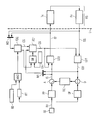
- FIG. 1 shows a diagrammatic representation of one embodiment of a control process for controlling a signal with a plurality of independent components.
- the high-frequency transmit unit is, for example, a corresponding transmitter Tx, to which a baseband signal IS′ is fed.
- the transmitter Tx amplifies the baseband signal IS′ using a high-frequency amplifier and modulates the baseband signal IS′ with a high-frequency carrier signal that lies in the range between one and several hundred megahertz (e.g. 120 MHz).
- a maximum frequency of the baseband signal is, for example, approximately 500 kHz.
- the transmitter Tx is a transmitter used in a nuclear spin tomography system, for example, and transmits high-frequency pulses to excite atoms in a human body or an animal body in order, in combination with a corresponding magnetic field, to generate images of the body.
- the emitted high-frequency signal is subject to undesired fluctuations, resulting in errors with respect to the imaging performed by the tomography system.
- a control process as described below, is used.
- the high-frequency signal generated by the transmitter Tx is received by a corresponding high-frequency receive unit Rx that amplifies the high-frequency signal and demodulates the high-frequency signal as appropriate, so that a demodulated baseband signal is received as an output signal OS. Due to the transmit unit Tx, the receive unit Rx, and a signal transmission path between the transmit unit Tx and the receive unit Rx, a control path RS that lies on the right-hand side of vertical dashed line L in FIG. 1 is created.
- the baseband signal includes a real part and an imaginary part as independent Cartesian components (e.g., two Cartesian components) to be controlled.
- the two Cartesian components describe an amplitude and a phase of the baseband signal.
- the two Cartesian components may, for example, be adjusted independently of one another, but are coupled to one another by the control path RS.
- the real part and the imaginary part of the baseband signal may not be controlled separately, since there is interference between the real part and imaginary part.
- a 2 ⁇ 2 matrix with non-diagonal elements not equal to zero is used in the control process in order to take account of the coupling between the real part and the imaginary part.
- the complexity of the controller increases quadratically with the number of Cartesian components controlled.
- a control process in which a diagonal controller with a simple structure may be used despite the coupling of the Cartesian components via the control path RS, is provided. This is achieved by an appropriate decoupling of the Cartesian components coupled via the control path RS, as described in the following.
- a desired or reference value RV (e.g., a reference signal), on which the baseband signal is to be controlled, is generated using a setup device SE.
- the desired or reference value RV is fed to an (optional) precontroller in the form of a feed-forward controller FF that adjusts the baseband signal to the high-frequency amplifier in the transmit unit Tx.
- a precontrol signal arrives at an adder A, in which the precontrol signal is additively coupled with an output of a diagonal controller DC.
- the reference signal RV is further fed to an (optional) setup filter SF.
- the setup filter SF in the control process, takes account of a corresponding dead time that is caused by a time lag during the signal transmission or signal generation via the control path RS.
- a signal that is time-congruent to the signal OS′ is generated using the dead time.
- the time-congruent signal is coupled with the signal of the setup filter SF via a subtractor D.
- a resulting difference signal is fed to the diagonal controller DC.
- a corresponding decoupling of the Cartesian components coupled via the control path RS is performed. This is achieved in the device in FIG. 1 by two coupling determination units FD 1 and FD 2 and two decoupling units LD 1 and LD 2 .
- the coupling between the Cartesian components is continuously determined via the coupling determination unit FD 1 as part of the control process, and a coupling signal CS based on the coupling is continuously generated or adjusted.
- the coupling signal represents, for example, a phase shift between the signals before and after the control path RS.
- an input signal IS is fed to the coupling determination unit FD 1 .
- the input signal IS is received (e.g., formed) in the adder A by the addition of the output signal of the diagonal controller to the precontrol signal and represents a manipulated variable of the control loop.
- the coupling determination unit FD 1 is fed the output signal OS′, which originates from the decoupling unit LD 1 described below.
- the two signals e.g., the input signal IS and the output signal OS′
- the coupling is, for example, determined in the coupling determination unit FD 1 by comparing the combined signals, which results in a coupling signal CS at an output of the coupling determination unit FD 1 .
- a further (optional) coupling determination unit FD 2 is used in FIG. 1 .
- the further coupling determination unit FD 2 unit unlike the coupling determination unit FD 1 , is not used for continuous correction of the coupling signal CS, but instead supplies, on a one-off basis or at predetermined points in time (e.g., triggered by a corresponding trigger), an updated coupling signal CS that is looped via the coupling determination unit FD 1 and arrives at the decoupling unit LD 1 .
- the coupling determination unit FD 2 may be used at the start of the control process in order to perform an immediate identification of the coupling, so that the controller is activated faster.
- the coupling determination unit FD 2 is fed the baseband signal IS′ at an input of the control path RS and the coupled output signal OS at an output of the control path RS via a further signal combiner M 2 . By comparing the combined signals, the further coupling determination unit FD 2 determines the coupling signal CS. Both the coupling determination unit FD 1 and the further coupling determination unit FD 2 determine the coupling signal on the basis of a feedback decoupling.
- FIG. 1 shows a variant for how the further coupling determination unit FD 2 may be put into service.
- the further coupling unit FD 2 is, for example, activated via an output of an AND gate, where if a logical 1 resides at an AND gate output, the further coupling determination unit FD 2 is activated and determines a corresponding coupling signal CS. So that a logical 1 is generated at the output of the AND gate, function units (e.g., an enable by trigger (ET) function unit and an enable on demand (ED) function unit) have a logical 1 at inputs (e.g., both inputs) of the AND gate.
- E enable by trigger
- ED enable on demand
- the function unit ET for example, generates a logical 1 whenever the function unit ET is fed a sufficient desired value level via unit SE.
- the function unit FD 1 may be put into service using a trigger signal if in addition to a sufficient desired value level, a logical 1 is generated by the function unit ED.
- the use of the coupling determination unit FD 1 is controlled via a corresponding OR gate.
- the further coupling determination unit FD 2 is put into service.
- the logical OR gate for example, generates a logical 1 if a logical 1 resides at at least one input of the logical OR gate.
- An input is, for example, fed through an enable always (EA) function unit, with which it is provided that the further coupling determination unit FD 2 is put into service by the generation of a corresponding logical 1.
- EA enable always
- a logical 0 is generated by the function unit EA, the entry into service of the coupling determination unit FD 1 is controlled via a corresponding output signal from the further coupling determination unit FD 2 .
- a logical 1 is generated by the further coupling determination unit FD 2 whenever the further coupling determination unit FD 2 is not in service, so that the coupling is updated by the coupling determination unit FD 1 .
- the determination of the coupling signal CS on the basis of the coupling determination unit FD 1 or the further coupling determination unit FD 2 is followed by the actual decoupling in the decoupling units LD 1 or LD 2 (e.g., a loop decoupler) that represent loop decouplers (LD).
- the individual decoupling units LD 1 and LD 2 implement a corresponding rotational matrix, with which a phase shift specified in the coupling signal is reversed.
- the loop decoupler LD 1 represents a component of the control process in FIG. 1 , where the loop decoupler LD 2 is an optional component.
- the decoupler LD 1 is, for example, fed the coupled output signal OS from the control path RS and the coupling signal CS.
- a decoupled output signal OS′ may be determined in the decoupler.
- a real part and an imaginary part of the decoupled output signal OS′ are decoupled.
- a decoupling may also be effected on the input side via the decoupler LD 2 , where the input signal IS and the coupling signal CS are fed to the decoupler LD 2 .
- the decoupler LD 2 determines the baseband signal IS′ (e.g., a decoupled input signal).
- the decoupler LD 2 is, for example, used if nonlinearities that cannot be sufficiently taken into account merely by decoupling on the output side occur on the input side of the control path RS.
- the decoupled output signal OS′ is received in total and is combined with the desired value via the subtractor. Since a signal with a decoupled real and imaginary part resides at the input of the controller DC, both Cartesian components may be controlled separately via a diagonal controller, the matrix of which contains components only along the diagonal.
- the diagonal controller corresponds, for example, to a combination of two separate single-variable controllers.
- a diagonal controller of this type is significantly simpler in design than controllers, in which couplings are to be processed between the components of the control variable.
- the Cartesian components of the actuating signal may be coupled to one another for a control path, and a simple control process with a diagonal controller may be achieved by using a corresponding decoupling.
- This decoupling provides that the thereby obtained cumulative effect paths no longer have any coupling.
- the control process is, for example, significantly simpler in design and implementation and simultaneously is more dynamic in performance.
- the decoupling may be implemented continuously by updating the correspondingly determined coupling signal in order to take account of dynamic changes in the control path.
- the coupling signal may be recalculated only during initialization of the method or at dedicated points in time. Both variants may also be combined with one another.
- the method of the present embodiments is described on the basis of the control process of a high-frequency transmit unit for a nuclear spin tomography system.
- a nuclear spin tomography system a plurality of transmit units that work on different channels may be used.
- a corresponding control process of the present embodiments may be implemented for each of the transmit units.
- the method is additionally not limited to the use of transmit units in nuclear spin tomography systems.
- the method may also be used in other technical fields, in which an actuating signal is coupled to a plurality of independent components via a control path.
- a further area of application is, for example, the control process for electric drives in a.c. machines, where the torque-generating current and the field-generating current are to be influenced separately from one another as independent components.
Landscapes
- Physics & Mathematics (AREA)
- Condensed Matter Physics & Semiconductors (AREA)
- General Physics & Mathematics (AREA)
- Apparatus For Radiation Diagnosis (AREA)
- Magnetic Resonance Imaging Apparatus (AREA)
- Feedback Control In General (AREA)
Abstract
Description
Claims (16)
Applications Claiming Priority (3)
| Application Number | Priority Date | Filing Date | Title |
|---|---|---|---|
| DE102010035918.1A DE102010035918B4 (en) | 2010-08-31 | 2010-08-31 | Method and device for controlling a signal with a plurality of independent components |
| DE102010035918.1 | 2010-08-31 | ||
| DE102010035918 | 2010-08-31 |
Publications (2)
| Publication Number | Publication Date |
|---|---|
| US20120224647A1 US20120224647A1 (en) | 2012-09-06 |
| US9841474B2 true US9841474B2 (en) | 2017-12-12 |
Family
ID=45566004
Family Applications (1)
| Application Number | Title | Priority Date | Filing Date |
|---|---|---|---|
| US13/221,652 Expired - Fee Related US9841474B2 (en) | 2010-08-31 | 2011-08-30 | Method and device for controlling a signal with a plurality of independent components |
Country Status (2)
| Country | Link |
|---|---|
| US (1) | US9841474B2 (en) |
| DE (1) | DE102010035918B4 (en) |
Families Citing this family (2)
| Publication number | Priority date | Publication date | Assignee | Title |
|---|---|---|---|---|
| DE102013208519B3 (en) | 2013-05-08 | 2014-10-23 | Siemens Aktiengesellschaft | Method for generating a signal |
| DE102014000943A1 (en) | 2014-01-24 | 2015-07-30 | Dietmar Dreyer | Technical user program for use in semiconductor amplifiers for the storage of electrical energy |
Citations (14)
| Publication number | Priority date | Publication date | Assignee | Title |
|---|---|---|---|---|
| US4963831A (en) * | 1988-05-02 | 1990-10-16 | U.S. Philips Corporation | Self adjusting frequency demodulating integrated circuit |
| US5400247A (en) * | 1992-06-22 | 1995-03-21 | Measurex Corporation, Inc. | Adaptive cross-directional decoupling control systems |
| US20020065048A1 (en) * | 1999-07-28 | 2002-05-30 | Kazuo Nagatani | Method and apparatus for compensating for distortion in radio apparatus |
| DE10163339A1 (en) | 2001-12-21 | 2003-07-03 | Volkswagen Ag | Method and equipment for automatic control of process variables of IC engine, provides decoupling of individual control signal or different process variables |
| DE10246910A1 (en) | 2002-10-08 | 2004-05-06 | Mtu Aero Engines Gmbh | Multi-size control system and method for controlling a multi-size control system |
| US6801037B1 (en) * | 2000-05-11 | 2004-10-05 | Fonar Corporation | Dynamic real-time magnetic resonance imaging sequence designer |
| WO2007090220A1 (en) | 2006-02-07 | 2007-08-16 | Technische Universität Wien | Method for regulating a process |
| US20070222449A1 (en) * | 2004-02-26 | 2007-09-27 | Hoult David I | Method of Effecting Nuclear Magnetic Resonance Experiments Using Cartesian Feedback |
| US20080158640A1 (en) * | 2006-12-05 | 2008-07-03 | Fujitsu Limited | Optical apparatus utilizing modulation based on a tertiary drive signal, optical transmitter, and optical transmission system |
| US20080159362A1 (en) * | 2006-12-29 | 2008-07-03 | Clearwire Corporation | System and method for adaptive modulation and power control in a wireless communication system |
| US20090058714A1 (en) * | 2007-04-13 | 2009-03-05 | Honeywell International Inc. | History or image based methods for altitude determination in a radar altimeter |
| US20090060381A1 (en) * | 2007-08-31 | 2009-03-05 | Ethicon Endo-Surgery, Inc. | Dynamic range and amplitude control for imaging |
| US20100036211A1 (en) * | 2006-11-07 | 2010-02-11 | Washington State University | Systems and methods for measuring physiological parameters of a body |
| US20100098195A1 (en) * | 2008-10-20 | 2010-04-22 | Michael Nekhamkin | Systems and methods for frequency offset correction in a digital radio broadcast receiver |
-
2010
- 2010-08-31 DE DE102010035918.1A patent/DE102010035918B4/en not_active Expired - Fee Related
-
2011
- 2011-08-30 US US13/221,652 patent/US9841474B2/en not_active Expired - Fee Related
Patent Citations (16)
| Publication number | Priority date | Publication date | Assignee | Title |
|---|---|---|---|---|
| US4963831A (en) * | 1988-05-02 | 1990-10-16 | U.S. Philips Corporation | Self adjusting frequency demodulating integrated circuit |
| US5400247A (en) * | 1992-06-22 | 1995-03-21 | Measurex Corporation, Inc. | Adaptive cross-directional decoupling control systems |
| DE19501077A1 (en) | 1992-06-22 | 1996-07-18 | Measurex Corp | Adaptive cross directional decoupling control systems |
| US20020065048A1 (en) * | 1999-07-28 | 2002-05-30 | Kazuo Nagatani | Method and apparatus for compensating for distortion in radio apparatus |
| US6801037B1 (en) * | 2000-05-11 | 2004-10-05 | Fonar Corporation | Dynamic real-time magnetic resonance imaging sequence designer |
| DE10163339A1 (en) | 2001-12-21 | 2003-07-03 | Volkswagen Ag | Method and equipment for automatic control of process variables of IC engine, provides decoupling of individual control signal or different process variables |
| DE10246910A1 (en) | 2002-10-08 | 2004-05-06 | Mtu Aero Engines Gmbh | Multi-size control system and method for controlling a multi-size control system |
| US20060004470A1 (en) | 2002-10-08 | 2006-01-05 | Mtu Aero Engines Gmbh | Multivalue control system and method for controlling a multivalue controlled system |
| US20070222449A1 (en) * | 2004-02-26 | 2007-09-27 | Hoult David I | Method of Effecting Nuclear Magnetic Resonance Experiments Using Cartesian Feedback |
| WO2007090220A1 (en) | 2006-02-07 | 2007-08-16 | Technische Universität Wien | Method for regulating a process |
| US20100036211A1 (en) * | 2006-11-07 | 2010-02-11 | Washington State University | Systems and methods for measuring physiological parameters of a body |
| US20080158640A1 (en) * | 2006-12-05 | 2008-07-03 | Fujitsu Limited | Optical apparatus utilizing modulation based on a tertiary drive signal, optical transmitter, and optical transmission system |
| US20080159362A1 (en) * | 2006-12-29 | 2008-07-03 | Clearwire Corporation | System and method for adaptive modulation and power control in a wireless communication system |
| US20090058714A1 (en) * | 2007-04-13 | 2009-03-05 | Honeywell International Inc. | History or image based methods for altitude determination in a radar altimeter |
| US20090060381A1 (en) * | 2007-08-31 | 2009-03-05 | Ethicon Endo-Surgery, Inc. | Dynamic range and amplitude control for imaging |
| US20100098195A1 (en) * | 2008-10-20 | 2010-04-22 | Michael Nekhamkin | Systems and methods for frequency offset correction in a digital radio broadcast receiver |
Non-Patent Citations (1)
| Title |
|---|
| German Office Action dated Apr. 6, 2011 for corresponding German Patent Application No. DE 10 2010 035 918.1-35 with English translation. |
Also Published As
| Publication number | Publication date |
|---|---|
| DE102010035918A1 (en) | 2012-03-01 |
| US20120224647A1 (en) | 2012-09-06 |
| DE102010035918B4 (en) | 2014-01-09 |
Similar Documents
| Publication | Publication Date | Title |
|---|---|---|
| EP0831594B1 (en) | Frequency cancelling system and method | |
| US8742898B2 (en) | Apparatus for removing transmission leakage signal in RFID system and RFID system having the same | |
| US11092660B2 (en) | Pilot tone identification | |
| US9841474B2 (en) | Method and device for controlling a signal with a plurality of independent components | |
| JP2009513217A (en) | Active decoupling of transmitters in MRI | |
| KR20130055326A (en) | Receiver and transmitter of coping with interference in super-regenerative communication system, and method using the devices | |
| CN109009113B (en) | Motion detection devices, methods, and magnetic resonance imaging systems and methods | |
| JP6950632B2 (en) | Power transmission device that supplies power wirelessly and foreign matter detection method | |
| US10177852B2 (en) | Method and apparatus for automatically controlling bias voltage of optical modulator | |
| KR20150057319A (en) | Satellite Navigation Complex Jamming Signal Generation Device and Control Method thereof | |
| WO2009111027A3 (en) | Optimization of rf transmit and gradient magnetic field imaging using radio frequency and gradient coils | |
| CN105286997A (en) | Method for adjusting a volume level of a communications unit and a communications unit | |
| US20140167760A1 (en) | System for communication usable by magnetic resonance and other imaging devices | |
| US8502533B2 (en) | Combined imaging system, including a magnetic resonance system and a UWB radar | |
| CN101909519B (en) | Position control of medical appliances in the human body by means of phase difference measurement | |
| JP2009081719A (en) | Noise canceling method and noise canceller | |
| US6304085B2 (en) | Auxiliary apparatus for a magnetic resonance tomography apparatus control unit | |
| KR102535405B1 (en) | Method and Apparatus of Microwave Focusing and Thermal Imaging for Biological Tissues | |
| JP4195423B2 (en) | Magnetic resonance excitation signal generator | |
| CN110895317A (en) | Magnetic resonance imaging radio frequency system and radio frequency control method and magnetic resonance imaging system | |
| US8749354B2 (en) | RFID system and method for removing transmission leakage signal thereof | |
| US9696394B2 (en) | Magnetic resonance system having variable frequency transmit pulses | |
| US20080169725A1 (en) | Piezoelectric actuation system | |
| US6927627B2 (en) | Amplifier power control in frequency hopping applications and methods | |
| US10782372B2 (en) | Magnetic resonance imaging system radio frequency subsystem and coil decoupling apparatus and methods used therein |
Legal Events
| Date | Code | Title | Description |
|---|---|---|---|
| AS | Assignment |
Owner name: SIEMENS AKTIENGESELLSCHAFT, GERMANY Free format text: ASSIGNMENT OF ASSIGNORS INTEREST;ASSIGNORS:HUBER, KLAUS;JUNGKUNZ, CLEMENS;MARTIUS, SEBASTIAN;AND OTHERS;SIGNING DATES FROM 20111004 TO 20111006;REEL/FRAME:027239/0242 |
|
| STCF | Information on status: patent grant |
Free format text: PATENTED CASE |
|
| AS | Assignment |
Owner name: SIEMENS HEALTHCARE GMBH, GERMANY Free format text: ASSIGNMENT OF ASSIGNORS INTEREST;ASSIGNOR:SIEMENS AKTIENGESELLSCHAFT;REEL/FRAME:046380/0273 Effective date: 20180518 |
|
| MAFP | Maintenance fee payment |
Free format text: PAYMENT OF MAINTENANCE FEE, 4TH YEAR, LARGE ENTITY (ORIGINAL EVENT CODE: M1551); ENTITY STATUS OF PATENT OWNER: LARGE ENTITY Year of fee payment: 4 |
|
| AS | Assignment |
Owner name: SIEMENS HEALTHINEERS AG, GERMANY Free format text: ASSIGNMENT OF ASSIGNORS INTEREST;ASSIGNOR:SIEMENS HEALTHCARE GMBH;REEL/FRAME:066088/0256 Effective date: 20231219 |
|
| AS | Assignment |
Owner name: SIEMENS HEALTHINEERS AG, GERMANY Free format text: CORRECTIVE ASSIGNMENT TO CORRECT THE ASSIGNEE PREVIOUSLY RECORDED AT REEL: 066088 FRAME: 0256. ASSIGNOR(S) HEREBY CONFIRMS THE ASSIGNMENT;ASSIGNOR:SIEMENS HEALTHCARE GMBH;REEL/FRAME:071178/0246 Effective date: 20231219 |
|
| FEPP | Fee payment procedure |
Free format text: MAINTENANCE FEE REMINDER MAILED (ORIGINAL EVENT CODE: REM.); ENTITY STATUS OF PATENT OWNER: LARGE ENTITY |
|
| LAPS | Lapse for failure to pay maintenance fees |
Free format text: PATENT EXPIRED FOR FAILURE TO PAY MAINTENANCE FEES (ORIGINAL EVENT CODE: EXP.); ENTITY STATUS OF PATENT OWNER: LARGE ENTITY |
|
| STCH | Information on status: patent discontinuation |
Free format text: PATENT EXPIRED DUE TO NONPAYMENT OF MAINTENANCE FEES UNDER 37 CFR 1.362 |
|
| FP | Lapsed due to failure to pay maintenance fee |
Effective date: 20251212 |