US9839520B2 - Artificial knee joint implant - Google Patents
Artificial knee joint implant Download PDFInfo
- Publication number
- US9839520B2 US9839520B2 US14/900,379 US201414900379A US9839520B2 US 9839520 B2 US9839520 B2 US 9839520B2 US 201414900379 A US201414900379 A US 201414900379A US 9839520 B2 US9839520 B2 US 9839520B2
- Authority
- US
- United States
- Prior art keywords
- distalmost
- anterior
- femoral component
- point
- tibial plate
- Prior art date
- Legal status (The legal status is an assumption and is not a legal conclusion. Google has not performed a legal analysis and makes no representation as to the accuracy of the status listed.)
- Expired - Fee Related, expires
Links
Images


Classifications
-
- A—HUMAN NECESSITIES
- A61—MEDICAL OR VETERINARY SCIENCE; HYGIENE
- A61F—FILTERS IMPLANTABLE INTO BLOOD VESSELS; PROSTHESES; DEVICES PROVIDING PATENCY TO, OR PREVENTING COLLAPSING OF, TUBULAR STRUCTURES OF THE BODY, e.g. STENTS; ORTHOPAEDIC, NURSING OR CONTRACEPTIVE DEVICES; FOMENTATION; TREATMENT OR PROTECTION OF EYES OR EARS; BANDAGES, DRESSINGS OR ABSORBENT PADS; FIRST-AID KITS
- A61F2/00—Filters implantable into blood vessels; Prostheses, i.e. artificial substitutes or replacements for parts of the body; Appliances for connecting them with the body; Devices providing patency to, or preventing collapsing of, tubular structures of the body, e.g. stents
- A61F2/02—Prostheses implantable into the body
- A61F2/30—Joints
- A61F2/38—Joints for elbows or knees
- A61F2/3836—Special connection between upper and lower leg, e.g. constrained
-
- A—HUMAN NECESSITIES
- A61—MEDICAL OR VETERINARY SCIENCE; HYGIENE
- A61F—FILTERS IMPLANTABLE INTO BLOOD VESSELS; PROSTHESES; DEVICES PROVIDING PATENCY TO, OR PREVENTING COLLAPSING OF, TUBULAR STRUCTURES OF THE BODY, e.g. STENTS; ORTHOPAEDIC, NURSING OR CONTRACEPTIVE DEVICES; FOMENTATION; TREATMENT OR PROTECTION OF EYES OR EARS; BANDAGES, DRESSINGS OR ABSORBENT PADS; FIRST-AID KITS
- A61F2/00—Filters implantable into blood vessels; Prostheses, i.e. artificial substitutes or replacements for parts of the body; Appliances for connecting them with the body; Devices providing patency to, or preventing collapsing of, tubular structures of the body, e.g. stents
- A61F2/02—Prostheses implantable into the body
- A61F2/30—Joints
- A61F2/38—Joints for elbows or knees
- A61F2/3859—Femoral components
-
- A—HUMAN NECESSITIES
- A61—MEDICAL OR VETERINARY SCIENCE; HYGIENE
- A61F—FILTERS IMPLANTABLE INTO BLOOD VESSELS; PROSTHESES; DEVICES PROVIDING PATENCY TO, OR PREVENTING COLLAPSING OF, TUBULAR STRUCTURES OF THE BODY, e.g. STENTS; ORTHOPAEDIC, NURSING OR CONTRACEPTIVE DEVICES; FOMENTATION; TREATMENT OR PROTECTION OF EYES OR EARS; BANDAGES, DRESSINGS OR ABSORBENT PADS; FIRST-AID KITS
- A61F2/00—Filters implantable into blood vessels; Prostheses, i.e. artificial substitutes or replacements for parts of the body; Appliances for connecting them with the body; Devices providing patency to, or preventing collapsing of, tubular structures of the body, e.g. stents
- A61F2/02—Prostheses implantable into the body
- A61F2/30—Joints
- A61F2/38—Joints for elbows or knees
- A61F2/389—Tibial components
-
- A—HUMAN NECESSITIES
- A61—MEDICAL OR VETERINARY SCIENCE; HYGIENE
- A61F—FILTERS IMPLANTABLE INTO BLOOD VESSELS; PROSTHESES; DEVICES PROVIDING PATENCY TO, OR PREVENTING COLLAPSING OF, TUBULAR STRUCTURES OF THE BODY, e.g. STENTS; ORTHOPAEDIC, NURSING OR CONTRACEPTIVE DEVICES; FOMENTATION; TREATMENT OR PROTECTION OF EYES OR EARS; BANDAGES, DRESSINGS OR ABSORBENT PADS; FIRST-AID KITS
- A61F2/00—Filters implantable into blood vessels; Prostheses, i.e. artificial substitutes or replacements for parts of the body; Appliances for connecting them with the body; Devices providing patency to, or preventing collapsing of, tubular structures of the body, e.g. stents
- A61F2/02—Prostheses implantable into the body
- A61F2/30—Joints
- A61F2002/30001—Additional features of subject-matter classified in A61F2/28, A61F2/30 and subgroups thereof
- A61F2002/30316—The prosthesis having different structural features at different locations within the same prosthesis; Connections between prosthetic parts; Special structural features of bone or joint prostheses not otherwise provided for
- A61F2002/30535—Special structural features of bone or joint prostheses not otherwise provided for
- A61F2002/30604—Special structural features of bone or joint prostheses not otherwise provided for modular
- A61F2002/30607—Kits of prosthetic parts to be assembled in various combinations for forming different prostheses
Definitions
- the present invention relates to an artificial knee joint implant including a femoral component and a tibial plate.
- JP 2004-166802A there is a known artificial knee joint including a femoral component that is fixed to a distal end of a femur and a tibial component (tibial plate) that is fixed to a proximal end of a tibia.
- This artificial knee joint is configured such that its medial pivot angle changes in accordance with a change in the flexion angle of the artificial knee joint.
- the femoral component and the tibial plate are positioned so as to maintain the balance between medial collateral ligament tension and lateral collateral ligament tension.
- the balance between both collateral ligaments may be poor, thus incurring a heavy burden on the patient's knee.
- the present invention solves the above-described problem, and it is an object thereof to provide an artificial knee joint implant with which the balance between ligaments can be properly adjusted.
- an aspect of the present invention is directed to an artificial knee joint implant, including a femoral component and a tibial plate, wherein the tibial plate has a tibia-side sliding face that slides against the femoral component, and the artificial knee joint implant includes a plurality of types of said tibial plates respectively having at least either the tibia-side sliding faces at different positions with respect to a tibia in a state where the tibial plates are fixed to a tibial tray attached to the tibia, or the tibia-side sliding faces in different shapes.
- a surgeon can select one of a plurality of types of tibial plates according to the shape, the condition, and the like of a knee joint of a patient, and attach that tibial plate to the patient's knee. Accordingly, the contact position of the femoral component and the tibial plate can be adjusted, and, thus, a proper balance between both collateral ligaments can be easily realized.
- the tibia-side sliding faces are respectively provided with distalmost points positioned on a distalmost side in an extension direction, which is a direction in which the artificial knee joint implant that is fixed to a femur and the tibia is extended, and each of the plurality of types of tibial plates has the distalmost point whose position with respect to a knee joint is different from the positions of the distalmost points of the other tibial plates in an anterior-posterior direction in a state where the tibial plates are fixed to the tibial tray.
- a plurality of types of tibial plates respectively having distalmost points at different positions in the anterior-posterior direction are formed as in this configuration, the contact position of the femoral component and the tibial plate in the anterior-posterior direction can be adjusted relatively easily.
- the distalmost points include a first distalmost point, a second distalmost point, and a third distalmost point respectively corresponding to the plurality of types of tibial plates
- the plurality of tibial plates include a first tibial plate provided with the first distalmost point that is at a predetermined position in the anterior-posterior direction, a second tibial plate provided with the second distalmost point that is closer to an anterior side than the first distalmost point is in the anterior-posterior direction, and a third tibial plate provided with the third distalmost point that is closer to a posterior side than the first distalmost point is in the anterior-posterior direction.
- first to third tibial plates can be formed in which the position of the distalmost point that realizes the most proper balance between ligaments of an average patient undergoing artificial knee joint replacement surgery is set to a first distalmost point, on the anterior side and the posterior side of which a second distalmost point and a third distalmost point are set.
- the first tibial plate is provided with a first medial-side distalmost point and a first lateral-side distalmost point as two first distalmost points that are spaced away from each other in a left-right direction
- the second tibial plate is provided with a second medial-side distalmost point and a second lateral-side distalmost point as two second distalmost points that are spaced away from each other in the left-right direction
- the third tibial plate is provided with a third medial-side distalmost point and a third lateral-side distalmost point as two third distalmost points that are spaced away from each other in the left-right direction
- separation intervals of the medial-side distalmost points in the anterior-posterior direction and separation intervals of the lateral-side distalmost points in the anterior-posterior direction are different from each other.
- the separation intervals of the first to third medial-side distalmost points in the anterior-posterior direction and the separation intervals of the first to third lateral-side distalmost points in the anterior-posterior direction can be properly set independently, and, thus, it is possible to provide an artificial knee joint implant that fits more patients.
- an aspect of the present invention is directed to an artificial knee joint implant, including a femoral component and a tibial plate, wherein the femoral component has a femur-side sliding face that slides over the tibial plate, and the artificial knee joint implant includes a plurality of types of said femoral components respectively having at least either the femur-side sliding faces at different positions with respect to a femur in a state where the femoral components are fixed to the femur, or the femur-side sliding faces in different shapes.
- a surgeon can select one of a plurality of types of femoral components according to the shape, the condition, and the like of a knee joint of a patient, and attach that femoral component to the patient's knee. Accordingly, the contact position of the femoral component and the tibial plate can be adjusted, and, thus, a proper balance between both collateral ligaments can be easily realized.
- the femur-side sliding faces are respectively provided with distalmost points positioned on a distalmost side in an extension direction, which is a direction in which the artificial knee joint implant that is fixed to the femur and a tibia is extended, and each of the plurality of types of femoral components has the distalmost point whose position with respect to a knee joint is different from the positions of the distalmost points of the other femoral components in an anterior-posterior direction in a state where the femoral components are fixed to the femur.
- a plurality of types of femoral components respectively having distalmost points at different positions in the anterior-posterior direction are formed as in this configuration, the contact position of the femoral component and the tibial plate in the anterior-posterior direction can be adjusted relatively easily.
- the distalmost points include a first distalmost point, a second distalmost point, and a third distalmost point respectively corresponding to the plurality of types of femoral components
- the plurality of femoral components include a first femoral component provided with the first distalmost point that is at a predetermined position in the anterior-posterior direction, a second femoral component provided with the second distalmost point that is closer to an anterior side than the first distalmost point is in the anterior-posterior direction, and a third femoral component provided with the third distalmost point that is closer to a posterior side than the first distalmost point is in the anterior-posterior direction.
- first to third femoral components can be formed in which the position of the distalmost point that realizes the most proper balance between ligaments of an average patient undergoing artificial knee joint replacement surgery is set to a first distalmost point, on the anterior side and the posterior side of which a second distalmost point and a third distalmost point are set.
- the first femoral component is provided with a first medial-side distalmost point and a first lateral-side distalmost point as two first distalmost points that are spaced away from each other in a left-right direction
- the second femoral component is provided with a second medial-side distalmost point and a second lateral-side distalmost point as two second distalmost points that are spaced away from each other in the left-right direction
- the third femoral component is provided with a third medial-side distalmost point and a third lateral-side distalmost point as two third distalmost points that are spaced away from each other in the left-right direction
- separation intervals of the medial-side distalmost points in the anterior-posterior direction and separation intervals of the lateral-side distalmost points in the anterior-posterior direction are different from each other.
- the separation intervals of the first to third medial-side distalmost points in the anterior-posterior direction and the separation intervals of the first to third lateral-side distalmost points in the anterior-posterior direction can be properly set independently, and, thus, it is possible to provide an artificial knee joint implant that fits more patients.
- FIG. 1 shows a partial cross-sectional view showing an example of an artificial knee joint implant in a state of use according to an embodiment, in a state of being attached to a femur and a tibia of patient.
- FIG. 2A shows view of a most inferior point standard-type femoral component, wherein FIG. 2A is a side view thereof.
- FIG. 2B shows view of a most inferior point standard-type femoral component, wherein FIG. 2B is a bottom view thereof.
- FIG. 3A shows view of a most inferior point anterior-type femoral component, wherein FIG. 3A is a side view thereof.
- FIG. 3B shows view of a most inferior point anterior-type femoral component, wherein FIG. 3B is a bottom view thereof.
- FIG. 4A shows view of a most inferior point posterior-type femoral component, wherein FIG. 4A is a side view thereof.
- FIG. 4B shows view of a most inferior point posterior-type femoral component, wherein FIG. 4B is a bottom view thereof.
- FIG. 5A shows view of a most inferior point standard-type tibial plate, wherein FIG. 5A is a plan view thereof.
- FIG. 5B shows view of a most inferior point standard-type tibial plate, wherein FIG. 5B is a cross-sectional view taken along the line VB-VB in FIG. 5A .
- FIG. 5C shows view of a most inferior point standard-type tibial plate, wherein FIG. 5C is a cross-sectional view taken along the line VC-VC in FIG. 5A .
- FIG. 6A shows view of a most inferior point anterior-type tibial plate, wherein FIG. 6A is a plan view thereof.
- FIG. 6B shows view of a most inferior point anterior-type tibial plate, wherein FIG. 6B is a cross-sectional view taken along the line VIB-VIB in FIG. 6A .
- FIG. 6C shows view of a most inferior point anterior-type tibial plate, wherein FIG. 6C is a cross-sectional view taken along the line VIC-VIC in FIG. 6A .
- FIG. 7A shows view of a most inferior point posterior-type tibial plate, wherein FIG. 7A is a plan view thereof.
- FIG. 7B shows view of a most inferior point posterior-type tibial plate, wherein FIG. 7B is a cross-sectional view taken along the line VIIB-VIIB in FIG. 7A .
- FIG. 7C shows view of a most inferior point posterior-type tibial plate, wherein FIG. 7C is a cross-sectional view taken along the line VIIC-VIIC in FIG. 7A .
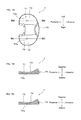
- FIGS. 8A to 8C show views illustrating a difference in an anterior-posterior direction between most inferior points respectively provided on a plurality of types of femoral components
- FIGS. 8D to 8F show views illustrating a difference in the anterior-posterior direction between most inferior points respectively provided on a plurality of types of tibial plates.
- FIG. 9A shows view of a state in which a femoral component and a tibial plate are attached to a patient's knee, wherein FIG. 9A is a view showing a combination of a standard-type femoral component and a standard-type tibial plate.
- FIG. 9B shows view of a state in which a femoral component and a tibial plate are attached to a patient's knee, wherein FIG. 9B is a view showing a combination of a standard-type femoral component and an anterior-type tibial plate.
- FIG. 9C shows view of a state in which a femoral component and a tibial plate are attached to a patient's knee, wherein FIG. 9C is a view showing a combination of a standard-type femoral component and a posterior-type tibial plate.
- FIG. 10A shows a view illustrating a positional relationship between most inferior points on a medial side and a lateral side respectively provided on a plurality of types of femoral components according to a modified example
- FIG. 10B is a view illustrating a positional relationship between most inferior points on a medial side and a lateral side respectively provided on a plurality of types of tibial plates according to a modified example.
- FIG. 11 shows cross-sectional views showing shapes of a plurality of types of tibial plates according to a modified example.
- FIG. 12A to 12F show views illustrating shapes of an artificial knee joint implant (PS-type) according to a modified example, wherein FIGS. 12A to 12C are side views respectively showing a plurality of types of femoral components, and FIGS. 12D to 12F are plan views respectively showing a plurality of types of tibial plates.
- PS-type artificial knee joint implant
- the present invention is widely applicable as an artificial knee joint implant including a femoral component and a tibial plate.
- FIG. 1 shows a partial cross-sectional view showing an example of a an artificial knee joint implant 1 in a state of use according to an embodiment of the present invention, in a state of being attached to a femur 101 and a tibia 102 of a patient, viewed from a side of the patient.
- the artificial knee joint implant 1 is used in surgery for replacing a knee joint of a patient with an artificial knee joint.
- the artificial knee joint implant 1 is used, for example, to recover normal functions of a patient's knee in which the knee joint has been highly deformed due to osteoarthritis, chronic rheumatoid arthritis, or the like.
- the artificial knee joint implant 1 is used in cruciate retaining (CR)-type artificial knee joint replacement surgery for replacing a knee joint of a patient with an artificial knee joint in a state where an anterior cruciate ligament of the patient has been removed but a posterior cruciate ligament is retained.
- CR cruciate retaining
- the artificial knee joint implant 1 includes a femoral component 3 and a tibial component 8 .
- the femoral component 3 is fixed to a distal end 101 a of the femur 101 .
- the tibial component 8 includes a tibial tray 9 and a tibial plate 6 .
- the tibial tray 9 has a flat plate portion 9 a formed in the shape of a flat plate and a projecting portion 9 b projecting to the inferior side from the flat plate portion 9 a , both of which are formed in one piece.
- the tibial tray 9 is fixed to the tibia 102 by allowing the projecting portion 9 b to be inserted into and fixed to a hole portion 102 b formed at a proximal end 102 a of the tibia 102 .
- the tibial plate 6 is fixed to a superior face of the flat plate portion 9 a of the tibial tray 9 fixed to the tibia 102 . Accordingly, the tibial plate 6 is fixed to the tibia 102 .
- the femoral component shown in FIG. 1 is a most inferior point standard-type femoral component 3
- the tibial plate 6 shown in FIG. 1 is a most inferior point standard-type tibial plate 6 (described later in detail).
- the artificial knee joint implant 1 includes a plurality of types (three types, in this embodiment) of femoral components and a plurality of types (three types, in this embodiment) of tibial plates.
- the artificial knee joint implant 1 includes, as the femoral components, the most inferior point standard-type femoral component 3 (first femoral component), a most inferior point anterior-type femoral component 2 (second femoral component), and a most inferior point posterior-type femoral component 4 (third femoral component).
- the artificial knee joint implant 1 includes, as the tibial plates, the most inferior point standard-type tibial plate 6 (first tibial plate), a most inferior point anterior-type tibial plate 5 (second tibial plate), and a most inferior point posterior-type tibial plate 7 (third tibial plate).
- FIGS. 2 to 4 are views respectively showing the most inferior point standard-type femoral component 3 , the most inferior point anterior-type femoral component 2 , and the most inferior point posterior-type femoral component 4 , wherein FIGS. 2A, 3 A, and 4 A are side views thereof, and FIGS. 2B, 3 B, and 4 B are bottom views thereof.
- FIGS. 5 to 7 are views respectively showing the most inferior point standard-type tibial plate 6 , the most inferior point anterior-type tibial plate 5 , and the most inferior point posterior-type tibial plate 7 , wherein FIGS. 5 A, 6 A, and 7 A are plan views thereof, and FIGS. 5B, 5C, 6B, 6C, 7B , and 7 C are cross-sectional views thereof.
- the direction indicated by the arrow “anterior” is referred to as an anterior side or an anterior direction
- the direction indicated by the arrow “posterior” is referred to as a posterior side or a posterior direction
- the direction indicated by the arrow “superior” is referred to as a superior side or a superior direction
- the direction indicated by the arrow “inferior” is referred to as an inferior side or an inferior direction
- the direction indicated by the arrow “right” is referred to as a right side
- the direction indicated by the arrow “left” is referred to as a left side.
- the anterior direction and the posterior direction in FIGS. 2 to 7 correspond to the anterior-posterior direction of a knee joint and a human body.
- the femoral components 2 , 3 , and 4 are different from each other in their shapes, in particular, in their shapes of femur-side sliding faces that slide over the tibial plate. Specifically, the femoral components 2 , 3 , and 4 are significantly different from each other in that most inferior points (distalmost points) provided on their femur-side sliding faces are at different positions with respect to a knee joint in the anterior-posterior direction.
- the tibial plates 5 , 6 , and 7 are different from each other in their shapes, in particular, in the shapes of their tibia-side sliding faces that slide against the femoral component. Specifically, the tibial plates 5 , 6 , and 7 are significantly different from each other in that the most inferior points (distalmost points) provided on their tibia-side sliding faces are at different positions with respect to a knee joint in the anterior-posterior direction.
- distalmost points are points positioned on the distalmost side in a direction (extension direction) in which the artificial knee joint implant attached to the patient's knee is extended.
- one femoral component and one tibial plate are selected from among the plurality of types of femoral components 2 , 3 , and 4 and tibial plates 5 , 6 , and 7 according to the shape, the condition, and the like of a knee joint of a patient, and are attached to the patient's knee.
- the femoral components there are three types of femoral components (the anterior-type femoral component 2 , the standard-type femoral component 3 , and the posterior-type femoral component 4 ). These three types of femoral components 2 , 3 , and 4 have substantially the same configuration except for the positions of the most inferior points in the anterior-posterior direction.
- the configuration of the standard-type femoral component 3 will be described first. Subsequently, the configurations of the anterior-type and posterior-type femoral components 2 and 4 will be described mainly focusing on aspects of the configurations different from those of the standard-type femoral component 3 .
- the standard-type femoral component 3 is made of, for example, a metal material having high biocompatibility. As shown in FIGS. 2A and 2B , the standard-type femoral component 3 has a substantial U-shape when viewed both from a side and from below.
- the standard-type femoral component 3 includes a medial condyle 31 and a lateral condyle 32 .
- the medial condyle 31 and the lateral condyle 32 are arranged side by side in the left-right direction.
- the anterior portion of the medial condyle 31 and the anterior portion of the lateral condyle 32 are connected to each other.
- the intermediate portion and the posterior portion of the medial condyle 31 and the intermediate portion and the posterior portion of the lateral condyle 32 are spaced away from each other in the left-right direction, and are arranged approximately parallel to each other in the anterior-posterior direction.
- the standard-type femoral component 3 is provided with, on an inner face thereof facing the distal end 101 a of the femur 101 , a fixing face 33 .
- the fixing face 33 is provided in order to fix the femoral component 3 to the distal end 101 a of the femur 101 .
- the fixing face 33 is provided with a projecting portion 34 projecting from the fixing face 33 .
- the fixing face 33 is fixed to the distal end 101 a in a state where the projecting portion 34 is inserted into a hole formed at the distal end 101 a of the femur 101 .
- the standard-type femoral component 3 is provided with, on an outer circumferential face thereof facing the side opposite from the distal end 101 a of the femur 101 , femur-side sliding faces 35 .
- the femur-side sliding faces 35 include a femur-medial-side sliding face 36 on the medial condyle 31 and a femur-lateral-side sliding face 37 on the lateral condyle 32 .
- the femur-medial-side sliding face 36 and the femur-lateral-side sliding face 37 are in the shape of a curved face projecting toward the side opposite from the distal end 101 a.
- Peak points of the sliding faces 36 and 37 projecting as described above are provided as most inferior points 36 a and 37 a (first distalmost points).
- the most inferior point 36 a provided on the medial-side sliding face 36 is provided as the first medial-side most inferior point 36 a
- the most inferior point 37 a provided on the lateral-side sliding face 37 is provided as the first lateral-side most inferior point 37 a .
- the first medial-side most inferior point 36 a and the first lateral-side most inferior point 37 a are positioned on the distalmost side in a state where the artificial knee joint implant 1 attached to a patient is extended.
- the most inferior points 36 a and 37 a are formed at substantially the same position as the position at which the projecting portion 34 is formed, in the anterior-posterior direction, in the standard-type femoral component 3 when viewed from a side.
- anterior-posterior positions of the most inferior points provided on the anterior-type femoral component 2 and the posterior-type femoral component 4 are different from those of the most inferior points provided on the standard-type femoral component 3 in the anterior-posterior direction.
- the other portions have substantially the same shapes.
- the anterior-type femoral component 2 also has a medial-side most inferior point 26 a (second distalmost point) provided on a femur-medial-side sliding face 26 of a medial condyle 21 and a lateral-side most inferior point 27 a (second distalmost point) provided on a femur-lateral-side sliding face 27 of a lateral condyle 22 , as in the case of the standard-type femoral component 3 .
- the medial-side most inferior point 26 a is provided as the second medial-side most inferior point 26 a
- the lateral-side most inferior point 27 a is provided as the second lateral-side most inferior point 27 a.
- the second medial-side most inferior point 26 a and the second lateral-side most inferior point 27 a are provided so as to be closer to the anterior side than the first medial-side most inferior point 36 a and the first lateral-side most inferior point 37 a provided on the standard-type femoral component 3 are in the anterior-posterior direction.
- the second medial-side most inferior point 26 a and the second lateral-side most inferior point 27 a are provided so as to be closer to the anterior side by 1 mm than the first medial-side most inferior point 36 a and the first lateral-side most inferior point 37 a are.
- FIG. 3 shows, in an exaggerated manner, the amount of difference of the most inferior points 26 a and 27 a of the anterior-type femoral component in the anterior-posterior direction, from the most inferior points 36 a and 37 a of the standard-type femoral component 3 .
- the posterior-type femoral component 4 also has a medial-side most inferior point 46 a (third distalmost point) provided on a femur-medial-side sliding face 46 of a medial condyle 41 and a lateral-side most inferior point 47 a (third distalmost point) provided on a femur-lateral-side sliding face 47 of a lateral condyle 42 , as in the case of the standard-type femoral component 3 .
- the medial-side most inferior point 46 a is provided as the third medial-side most inferior point 46 a
- the lateral-side most inferior point 47 a is provided as the third lateral-side most inferior point 47 a.
- the third medial-side most inferior point 46 a and the third lateral-side most inferior point 47 a are provided so as to be closer to the posterior side than the first medial-side most inferior point 36 a and the first lateral-side most inferior point 37 a provided on the standard-type femoral component 3 are in the anterior-posterior direction.
- the third medial-side most inferior point 46 a and the third lateral-side most inferior point 47 a are provided so as to be closer to the posterior side by 1 mm than the first medial-side most inferior point 36 a and the first lateral-side most inferior point 37 a are.
- the tibial plates there are three types of tibial plates (the anterior-type tibial plate 5 , the standard-type tibial plate 6 , and the posterior-type tibial plate 7 ). These three types of tibial plates 5 , 6 , and 7 have substantially the same configuration except for the positions of the most inferior points in the anterior-posterior direction.
- the configuration of the standard-type tibial plate 6 will be described first. Subsequently, the configurations of the anterior-type and posterior-type tibial plates 5 and 7 will be described mainly focusing on aspects of the configurations different from those of the standard-type tibial plate 6 .
- the standard-type tibial plate 6 is made of a synthetic resin or the like. As shown in FIG. 5 , the standard-type tibial plate 6 has a plate portion 60 formed substantially in the shape of a flat plate. The plate portion 60 is formed substantially in the shape of an ellipse that is elongated in the left-right direction. The plate portion 60 is provided with a medial recess 61 and a lateral recess 62 .
- the medial recess 61 is provided as a depression that is in slidable contact with one of the medial condyles 21 , 31 , and 41 of the femoral components 2 , 3 , and 4 .
- a face that slides against one of the femur-medial-side sliding faces 26 , 36 , and 46 of the femoral components 2 , 3 , and 4 is provided as a tibia-medial-side sliding face 63 .
- the lateral recess 62 is provided as a depression that is in slidable contact with one of the lateral condyles 22 , 32 , and 42 of the femoral components 2 , 3 , and 4 .
- a face that slides against one of the femur-lateral-side sliding faces 27 , 37 , and 47 of the femoral components 2 , 3 , and 4 is provided as a tibia-lateral-side sliding face 64 .
- the deepest recessed portions are provided as most inferior points 63 a and 64 a (first distalmost points).
- the most inferior point 63 a provided on the medial-side sliding face 63 is provided as the first medial-side most inferior point 63 a
- the most inferior point 64 a provided on the lateral-side sliding face 64 is provided as the first lateral-side most inferior point 64 a .
- the first medial-side most inferior point 63 a and the first lateral-side most inferior point 64 a are positioned on the distalmost side of the tibia 102 in a state where the artificial knee joint implant 1 attached to a patient is extended.
- the most inferior points 63 a and 64 a are formed at substantially the middle of the standard-type tibial plate 6 in the anterior-posterior direction, when viewed from a side.
- anterior-posterior positions of the most inferior points provided on the anterior-type tibial plate 5 and the posterior-type tibial plate 7 are different from those of the most inferior points provided on the standard-type tibial plate 6 in the anterior-posterior direction.
- the other portions have substantially the same shapes.
- the anterior-type tibial plate 5 also has a medial-side most inferior point 53 a (second distalmost point) provided on a tibia-medial-side sliding face 53 of a medial recess 51 and a lateral-side most inferior point 54 a (second distalmost point) provided on a tibia-lateral-side sliding face 54 of a lateral recess 52 , as in the case of the standard-type tibial plate 6 .
- the medial-side most inferior point 53 a is provided as the second medial-side most inferior point 53 a
- the lateral-side most inferior point 54 a is provided as the second lateral-side most inferior point 54 a.
- the second medial-side most inferior point 53 a and the second lateral-side most inferior point 54 a are provided so as to be closer to the anterior side than the first medial-side most inferior point 63 a and the first lateral-side most inferior point 64 a provided on the standard-type tibial plate 6 are in the anterior-posterior direction.
- the second medial-side most inferior point 53 a and the second lateral-side most inferior point 54 a are provided so as to be closer to the anterior side by 1 mm than the first medial-side most inferior point 63 a and the first lateral-side most inferior point 64 a are.
- FIG. 6 shows, in an exaggerated manner, the amount of difference of the most inferior points 53 a and 54 a of the anterior-type tibial plate in the anterior-posterior direction, from the most inferior points 63 a and 64 a of the standard-type tibial plate 6 .
- the posterior-type tibial plate 7 also has a medial-side most inferior point 73 a (third distalmost point) provided on a tibia-medial-side sliding face 73 of a medial recess 71 and a lateral-side most inferior point 74 a (third distalmost point) provided on a tibia-lateral-side sliding face 74 of a lateral recess 72 , as in the case of the standard-type tibial plate 6 .
- the medial-side most inferior point 73 a is provided as the third medial-side most inferior point 73 a
- the lateral-side most inferior point 74 a is provided as the third lateral-side most inferior point 74 a.
- the third medial-side most inferior point 73 a and the third lateral-side most inferior point 74 a are provided so as to be closer to the posterior side than the first medial-side most inferior point 63 a and the first lateral-side most inferior point 64 a provided on the standard-type tibial plate 6 are in the anterior-posterior direction.
- the third medial-side most inferior point 73 a and the third lateral-side most inferior point 74 a are provided so as to be closer to the posterior side by 1 mm than the first medial-side most inferior point 63 a and the first lateral-side most inferior point 64 a are.
- FIG. 7 shows, in an exaggerated manner, the amount of difference of the most inferior points 73 a and 74 a of the posterior-type tibial plate in the anterior-posterior direction, from the most inferior points 63 a and 64 a of the standard-type tibial plate 6 .
- FIG. 8 are views illustrating a difference in the anterior-posterior direction between most inferior points respectively provided on a plurality of types of femoral components and tibial plates.
- the most inferior points 26 a and 27 a of the anterior-type femoral component 2 shown in FIG. 8B are closer to the anterior side than the most inferior points 36 a and 37 a of the standard-type femoral component 3 shown in FIG. 8A are.
- the most inferior points 46 a and 47 a of the posterior-type femoral component 4 shown in FIG. 8C are closer to the posterior side than the most inferior points 36 a and 37 a of the standard-type femoral component 3 shown in FIG. 8A are.
- the most inferior points 53 a and 54 a of the anterior-type tibial plate 5 shown in FIG. 8E are closer to the anterior side than the most inferior points 63 a and 64 a of the standard-type tibial plate 6 shown in FIG. 8D are.
- the most inferior points 73 a and 74 a of the posterior-type tibial plate 7 shown in FIG. 8F are closer to the posterior side than the most inferior points 63 a and 64 a of the standard-type tibial plate 6 shown in FIG. 8D are.
- one femoral component and one tibial plate are selected from among the plurality of types of femoral components 2 , 3 , and 4 and tibial plates 5 , 6 , and 7 according to the shape, the condition, and the like of a knee joint of a patient, and are attached to the patient's knee.
- the surgeon judges that, in order to realize a proper balance between ligaments of a patient, the proper position of the femoral component with respect to the tibial plate in the anterior-posterior direction is a standard position, the surgeon selects a combination that realizes this positional relationship. Specifically, the surgeon selects the standard-type femoral component 3 and the standard-type tibial plate 6 , and attaches them to the patient's knee (see FIG. 9A ).
- the surgeon judges that, in order to realize a proper balance between ligaments of a patient, the proper position of the femoral component with respect to the tibial plate is an anterior position, the surgeon selects a combination that realizes this positional relationship. Specifically, for example, the surgeon selects the standard-type femoral component 3 and the anterior-type tibial plate 5 , and attaches them to the patient's knee.
- FIG. 9B is a view showing a state in which the standard-type femoral component 3 and the anterior-type tibial plate 5 are attached to a patient's knee. If the standard-type femoral component 3 and the anterior-type tibial plate 5 are combined as shown in FIG. 9B , a protrusion amount D 2 in the anterior direction of the anterior end of the femoral component 3 with respect to the anterior end of the tibial plate 5 can be made larger than (D 1 ) in the case of FIG. 9A . That is to say, in the case of FIG. 9B , the femoral component 3 can be positioned closer to the anterior side with respect to the tibial plate 5 than in the case of FIG. 9A .
- a combination of the posterior-type femoral component 4 and the standard-type tibial plate 6 or a combination of the posterior-type femoral component 4 and the anterior-type tibial plate 5 also makes it possible for the femoral component to be positioned closer to the anterior side with respect to the tibial plate.
- the femoral component can be positioned significantly closer to the anterior side with respect to the tibial plate.
- the surgeon judges that, in order to realize a proper balance between ligaments of a patient, the proper position of the femoral component with respect to the tibial plate is a posterior position, the surgeon selects a combination that realizes this positional relationship. Specifically, for example, the surgeon selects the standard-type femoral component 3 and the posterior-type tibial plate 7 , and attaches them to the patient's knee.
- FIG. 9C is a view showing a state in which the standard-type femoral component 3 and the posterior-type tibial plate 7 are attached to a patient's knee. If the standard-type femoral component 3 and the posterior-type tibial plate 7 are combined as shown in FIG. 9C , a protrusion amount D 3 in the anterior direction of the anterior end of the femoral component 3 with respect to the anterior end of the tibial plate 7 can be made smaller than (D 1 ) in the case of FIG. 9A . That is to say, in the case of FIG. 9C , the femoral component 3 can be positioned closer to the posterior side with respect to the tibial plate 7 than in the case of FIG. 9A .
- a combination of the anterior-type femoral component 2 and the standard-type tibial plate 6 or a combination of the anterior-type femoral component 2 and the posterior-type tibial plate 7 also makes it possible for the femoral component to be positioned closer to the posterior side with respect to the tibial plate.
- the femoral component can be positioned significantly closer to the posterior side with respect to the tibial plate.
- a surgeon can select one of the plurality of types of tibial plates 5 , 6 , and 7 according to the shape, the condition, and the like of a knee joint of a patient, and attach that tibial plate to the patient's knee. Accordingly, the contact position of the femoral component and the tibial plate can be adjusted, and, thus, a proper balance between both collateral ligaments can be easily realized.
- the artificial knee joint implant 1 it is possible to provide an artificial knee joint implant with which the balance between ligaments can be properly adjusted.
- the contact position of the femoral components 2 , 3 , and 4 and the tibial plates 5 , 6 , and 7 in the anterior-posterior direction can be adjusted relatively easily.
- three tibial plates 5 , 6 , and 7 can be formed in which the positions of the most inferior points that realize the most proper balance between ligaments of an average patient undergoing artificial knee joint replacement surgery are set to the first most inferior points 63 a and 64 a , on the anterior side and the posterior side of which the second most inferior points 53 a and 54 a and the third most inferior points 73 a and 74 a are set. Accordingly, it is possible to provide an artificial knee joint implant with which the balance between ligaments can be properly adjusted for more patients.
- a surgeon can select one of the plurality of types of femoral components 2 , 3 , and 4 according to the shape, the condition, and the like of a knee joint of a patient, and attach that femoral component to the patient's knee. Accordingly, the contact position of the femoral components 2 , 3 , and 4 and the tibial plates 5 , 6 , and 7 can be adjusted, and, thus, a proper balance between both collateral ligaments can be easily realized.
- the contact position of the femoral components 2 , 3 , and 4 and the tibial plates 5 , 6 , and 7 in the anterior-posterior direction can be adjusted relatively easily.
- three femoral components 2 , 3 , and 4 can be formed in which the positions of the most inferior points that realize the most proper balance between ligaments of an average patient undergoing artificial knee joint replacement surgery are set to the first most inferior points 36 a and 37 a , on the anterior side and the posterior side of which the second most inferior points 26 a and 27 a and the third most inferior points 46 a and 47 a are set. Accordingly, it is possible to provide an artificial knee joint implant 1 with which the balance between ligaments can be properly adjusted for more patients.
- FIG. 10A is a view illustrating a positional relationship between most inferior points on the medial side and the lateral side respectively provided on a plurality of types of femoral components according to a modified example
- FIG. 10B is a view illustrating a positional relationship between most inferior points on the medial side and the lateral side respectively provided on a plurality of types of tibial plates according to the modified example.
- the separation intervals of the medial-side most inferior points 26 a , 36 a , and 46 a in the anterior-posterior direction and the separation intervals of the lateral-side most inferior points 27 a , 37 a , and 47 a in the anterior-posterior direction of the femoral components 2 , 3 , and 4 are the same (1 mm), but there is no limitation to this.
- the separation intervals of the medial-side most inferior points in the anterior-posterior direction and the separation intervals of the lateral-side most inferior points in the anterior-posterior direction of the femoral components may be set to be different from each other. Accordingly, the separation intervals of the medial-side most inferior points and the separation intervals of the lateral-side most inferior points in the anterior-posterior direction can be properly set independently, and, thus, it is possible to provide an artificial knee joint implant that fits more patients.
- the separation intervals of the medial-side most inferior points in the anterior-posterior direction and the separation intervals of the lateral-side most inferior points in the anterior-posterior direction of the tibial plates may be set to be different from each other as well. Accordingly, the separation intervals of the medial-side most inferior points and the separation intervals of the lateral-side most inferior points in the anterior-posterior direction can be properly set independently, and, thus, it is possible to provide an artificial knee joint implant that fits more patients.
- the plurality of types of tibial plates 5 , 6 , and 7 are provided with the most inferior points 53 a , 54 a , 63 a , 64 a , 73 a , and 74 a , but there is no limitation to this. That is to say, even if the tibial plates do not have most inferior points at different anterior-posterior positions, it is sufficient that the tibial plates respectively have at least either tibia-side sliding faces at different positions with respect to the tibia in a state where the tibial plates are fixed to the tibia, or tibia-side sliding faces in different shapes.
- FIGS. 11A, 11B, and 11C are cross-sectional views showing a plurality of types of first to third tibial plates 5 a , 6 a , and 7 a according to a modified example.
- the tibial plates 5 a , 6 a , and 7 a have tibia-side sliding faces 55 , 65 , and 75
- the tibia-side sliding faces 55 , 65 , and 75 respectively have inclined faces 56 , 66 , and 76 formed on the anterior side and flat faces 57 , 67 , and 77 formed on the posterior side.
- the plurality of types of tibial plates 5 a , 6 a , 7 a according to this modified example are provided with the inclined faces 56 , 66 , and 76 that have different lengths in the anterior-posterior direction.
- the second tibial plate 5 a is provided with the inclined face 56 that has the shortest length in the anterior-posterior direction
- the third tibial plate 7 a is provided with the inclined face 76 that has the longest length in the anterior-posterior direction.
- FIG. 12 shows views illustrating shapes of a femoral component and a tibial plate in the case where the present invention is applied to a PS-type artificial knee joint, wherein FIGS. 12A to 12C are views of a femoral component, and FIGS. 12D to 12F are views of a tibial plate.
- FIG. 12A is a view of a most inferior point standard-type femoral component 3 b
- FIG. 12B is a view of a most inferior point anterior-type femoral component 2 b
- FIG. 12C is a view of a most inferior point posterior-type femoral component 4 b .
- FIG. 12A is a view of a most inferior point standard-type femoral component 3 b
- FIG. 12B is a view of a most inferior point anterior-type femoral component 2 b
- FIG. 12C is a view of a most inferior point posterior-type femoral component 4 b .
- FIG. 12D is a view of a most inferior point standard-type tibial plate 6 b
- FIG. 12E is a view of a most inferior point anterior-type tibial plate 5 b
- FIG. 12F is a view of a most inferior point posterior-type tibial plate 7 b.
- the femoral components 2 b , 3 b , and 4 b are respectively provided with cams 28 , 38 , and 48
- the tibial plates 5 b , 6 b , and 7 b are respectively provided with posts 58 , 68 , and 78 .
- the artificial knee joint implant according to this modified example is configured such that, when the flexion angle of the knee is a predetermined angle or more, one of the cams 28 , 38 , and 48 and one of the posts 58 , 68 , and 78 are brought into contact with each other to guide the flexion movement of the knee.
- the plurality of types of femoral components 2 b , 3 b , and 4 b respectively have the most inferior points at different positions in the anterior-posterior direction.
- the plurality of types of tibial plates 5 b , 6 b , and 7 b respectively have the most inferior points at different positions in the anterior-posterior direction. Accordingly, as in the foregoing embodiment, it is possible to provide an artificial knee joint implant with which the balance between ligaments can be properly adjusted.
- the artificial knee joint implant 1 is provided with the plurality of types of femoral components 2 , 3 , and 4 and the plurality of types of tibial plates 5 , 6 , and 7 , but there is no limitation to this, and the artificial knee joint implant 1 may be provided with a plurality of types of femoral components and one tibial plate or a plurality of types of tibial plates and one femoral component.
- the present invention is widely applicable as an artificial knee joint implant including a femoral component and a tibial plate.
Landscapes
- Health & Medical Sciences (AREA)
- Orthopedic Medicine & Surgery (AREA)
- Physical Education & Sports Medicine (AREA)
- Cardiology (AREA)
- Oral & Maxillofacial Surgery (AREA)
- Transplantation (AREA)
- Engineering & Computer Science (AREA)
- Biomedical Technology (AREA)
- Heart & Thoracic Surgery (AREA)
- Vascular Medicine (AREA)
- Life Sciences & Earth Sciences (AREA)
- Animal Behavior & Ethology (AREA)
- General Health & Medical Sciences (AREA)
- Public Health (AREA)
- Veterinary Medicine (AREA)
- Prostheses (AREA)
Abstract
Description
Claims (7)
Applications Claiming Priority (3)
| Application Number | Priority Date | Filing Date | Title |
|---|---|---|---|
| JP2013134777A JP6293426B2 (en) | 2013-06-27 | 2013-06-27 | Total knee implant |
| JP2013-134777 | 2013-06-27 | ||
| PCT/JP2014/067044 WO2014208687A1 (en) | 2013-06-27 | 2014-06-26 | Artificial knee joint implant |
Publications (2)
| Publication Number | Publication Date |
|---|---|
| US20160158020A1 US20160158020A1 (en) | 2016-06-09 |
| US9839520B2 true US9839520B2 (en) | 2017-12-12 |
Family
ID=52142013
Family Applications (1)
| Application Number | Title | Priority Date | Filing Date |
|---|---|---|---|
| US14/900,379 Expired - Fee Related US9839520B2 (en) | 2013-06-27 | 2014-06-26 | Artificial knee joint implant |
Country Status (5)
| Country | Link |
|---|---|
| US (1) | US9839520B2 (en) |
| EP (1) | EP3015092A4 (en) |
| JP (1) | JP6293426B2 (en) |
| CN (1) | CN105338927B (en) |
| WO (1) | WO2014208687A1 (en) |
Cited By (1)
| Publication number | Priority date | Publication date | Assignee | Title |
|---|---|---|---|---|
| US11911280B2 (en) | 2022-01-23 | 2024-02-27 | Optimotion Implants LLC | Knee prosthesis |
Families Citing this family (2)
| Publication number | Priority date | Publication date | Assignee | Title |
|---|---|---|---|---|
| CN107693167B (en) * | 2017-11-02 | 2024-01-16 | 北京安颂科技有限公司 | Tibial insert prosthesis, tibial prosthesis and artificial knee joint |
| CN111616842A (en) * | 2020-05-27 | 2020-09-04 | 北京市春立正达医疗器械股份有限公司 | Cruciate ligament-retaining type tibial platform pad and knee joint prosthesis applying same |
Citations (21)
| Publication number | Priority date | Publication date | Assignee | Title |
|---|---|---|---|---|
| US5080675A (en) | 1990-03-12 | 1992-01-14 | Howmedica | Tibial component for a replacement knee prosthesis |
| US5702464A (en) * | 1996-02-20 | 1997-12-30 | Smith & Nephew Inc. | Modular trial tibial insert |
| WO1999034755A1 (en) | 1997-12-31 | 1999-07-15 | Euro . Medic | Knee prosthesis |
| US20020156535A1 (en) | 2000-03-13 | 2002-10-24 | Biomedical Engineering Trust I | Posterior stabilized knee replacement with bearing translation for knees with retained collateral ligaments |
| JP2004166802A (en) | 2002-11-18 | 2004-06-17 | Kobe Steel Ltd | Artificial knee joint |
| US20050197709A1 (en) | 2004-02-27 | 2005-09-08 | Roberto Schaefer | Medial and lateral femoral implants for single-compartment knee prosthesis |
| US20070100463A1 (en) | 2005-10-31 | 2007-05-03 | Aram Luke J | Modular fixed and mobile bearing prosthesis system |
| US20080058945A1 (en) | 2006-03-13 | 2008-03-06 | Mako Surgical Corp. | Prosthetic device and system and method for implanting prosthetic device |
| US20080140212A1 (en) | 2001-05-15 | 2008-06-12 | Robert Metzger | Elongated femoral component |
| EP1974694A1 (en) | 2007-03-30 | 2008-10-01 | DePuy Products, Inc. | Mobile tibial bearing assembly |
| CN101431968A (en) | 2006-03-13 | 2009-05-13 | 马科外科公司 | Prosthetic device and method and system for implanting a prosthesis |
| US20090204222A1 (en) | 2008-02-11 | 2009-08-13 | Albert Burstein | Knee prosthesis system with at least a first tibial portion element (a tibial insert or tibial trial) and a second tibial portion element (a tibial insert or tibial trial), wherein each of the first tibial portion element and the second tibial portion element has a different slope |
| CN101708138A (en) | 2009-02-12 | 2010-05-19 | 北京爱康宜诚医疗器材有限公司 | Artificial knee joint bone fusion prosthesis |
| US20110029091A1 (en) * | 2009-02-25 | 2011-02-03 | Conformis, Inc. | Patient-Adapted and Improved Orthopedic Implants, Designs, and Related Tools |
| US20110178606A1 (en) | 2010-01-21 | 2011-07-21 | Depuy Products, Inc. | Tibial components for a knee prosthesis system |
| US20110251695A1 (en) | 2010-04-13 | 2011-10-13 | Lenz Nathaniel M | Systems and methods for tensioning ligaments and other soft tissues |
| US20110313534A1 (en) * | 2009-08-11 | 2011-12-22 | Medicinelodge, Inc. Dba Imds Co-Innovation | Systems and methods for prosthetic knee |
| US20120078263A1 (en) | 2010-09-10 | 2012-03-29 | Zimmer, Inc. | Bone preserving intraoperative downsizing system for orthopaedic implants |
| US20130060344A1 (en) * | 2011-09-07 | 2013-03-07 | Biomet Manufacturing Corp. | Femoral component with reinforced articulating surface |
| JP2013070738A (en) | 2011-09-27 | 2013-04-22 | Kyocera Medical Corp | Artificial knee joint implant |
| US20130226305A1 (en) * | 2010-09-10 | 2013-08-29 | Zimmer Gmbh | Femoral prosthesis with medialized patellar groove |
-
2013
- 2013-06-27 JP JP2013134777A patent/JP6293426B2/en active Active
-
2014
- 2014-06-26 WO PCT/JP2014/067044 patent/WO2014208687A1/en not_active Ceased
- 2014-06-26 US US14/900,379 patent/US9839520B2/en not_active Expired - Fee Related
- 2014-06-26 CN CN201480036638.9A patent/CN105338927B/en not_active Expired - Fee Related
- 2014-06-26 EP EP14817806.4A patent/EP3015092A4/en not_active Withdrawn
Patent Citations (32)
| Publication number | Priority date | Publication date | Assignee | Title |
|---|---|---|---|---|
| US5080675A (en) | 1990-03-12 | 1992-01-14 | Howmedica | Tibial component for a replacement knee prosthesis |
| US5702464A (en) * | 1996-02-20 | 1997-12-30 | Smith & Nephew Inc. | Modular trial tibial insert |
| WO1999034755A1 (en) | 1997-12-31 | 1999-07-15 | Euro . Medic | Knee prosthesis |
| US20020156535A1 (en) | 2000-03-13 | 2002-10-24 | Biomedical Engineering Trust I | Posterior stabilized knee replacement with bearing translation for knees with retained collateral ligaments |
| US20080140212A1 (en) | 2001-05-15 | 2008-06-12 | Robert Metzger | Elongated femoral component |
| JP2004166802A (en) | 2002-11-18 | 2004-06-17 | Kobe Steel Ltd | Artificial knee joint |
| US20050197709A1 (en) | 2004-02-27 | 2005-09-08 | Roberto Schaefer | Medial and lateral femoral implants for single-compartment knee prosthesis |
| US20070100463A1 (en) | 2005-10-31 | 2007-05-03 | Aram Luke J | Modular fixed and mobile bearing prosthesis system |
| JP2009513275A (en) | 2005-10-31 | 2009-04-02 | デピュイ・プロダクツ・インコーポレイテッド | Modular fixed and movable bearing prosthesis system |
| US20080058945A1 (en) | 2006-03-13 | 2008-03-06 | Mako Surgical Corp. | Prosthetic device and system and method for implanting prosthetic device |
| CN101431968A (en) | 2006-03-13 | 2009-05-13 | 马科外科公司 | Prosthetic device and method and system for implanting a prosthesis |
| JP2009529956A (en) | 2006-03-13 | 2009-08-27 | マコ サージカル コーポレーション | Prosthetic device and system and method for implanting a prosthetic device |
| EP1974694A1 (en) | 2007-03-30 | 2008-10-01 | DePuy Products, Inc. | Mobile tibial bearing assembly |
| CN101977570A (en) | 2008-02-11 | 2011-02-16 | 精密技术公司 | Knee prosthesis system with slope |
| US20090204222A1 (en) | 2008-02-11 | 2009-08-13 | Albert Burstein | Knee prosthesis system with at least a first tibial portion element (a tibial insert or tibial trial) and a second tibial portion element (a tibial insert or tibial trial), wherein each of the first tibial portion element and the second tibial portion element has a different slope |
| US8414653B2 (en) | 2008-02-11 | 2013-04-09 | Exactech, Inc. | Knee prosthesis system with at least a first tibial portion element (a tibial insert or tibial trial) and a second tibial portion element (a tibial insert or tibial trial), wherein each of the first tibial portion element and the second tibial portion element has a different slope |
| CN101708138A (en) | 2009-02-12 | 2010-05-19 | 北京爱康宜诚医疗器材有限公司 | Artificial knee joint bone fusion prosthesis |
| US20110029091A1 (en) * | 2009-02-25 | 2011-02-03 | Conformis, Inc. | Patient-Adapted and Improved Orthopedic Implants, Designs, and Related Tools |
| US20110313534A1 (en) * | 2009-08-11 | 2011-12-22 | Medicinelodge, Inc. Dba Imds Co-Innovation | Systems and methods for prosthetic knee |
| CN102133137A (en) | 2010-01-21 | 2011-07-27 | 德普伊产品公司 | Knee prosthesis system |
| US20110178606A1 (en) | 2010-01-21 | 2011-07-21 | Depuy Products, Inc. | Tibial components for a knee prosthesis system |
| WO2011130208A2 (en) | 2010-04-13 | 2011-10-20 | Smith & Nephew, Inc. | Systems and methods for tensioning ligaments and other soft tissues |
| CN102283724A (en) | 2010-04-13 | 2011-12-21 | 史密夫和内修有限公司 | Systems and methods for tensioning ligaments and other soft tissues |
| US20110251695A1 (en) | 2010-04-13 | 2011-10-13 | Lenz Nathaniel M | Systems and methods for tensioning ligaments and other soft tissues |
| US8496704B2 (en) | 2010-04-13 | 2013-07-30 | Smith & Nephew, Inc. | Systems and methods for tensioning ligaments and other soft tissues |
| US20130317620A1 (en) | 2010-04-13 | 2013-11-28 | Smith & Nephew, Inc. | Systems and methods for tensioning ligaments and other soft tissues |
| US9233002B2 (en) | 2010-04-13 | 2016-01-12 | Smith & Nephew, Inc. | Systems and methods for tensioning ligaments and other soft tissues |
| US20120078263A1 (en) | 2010-09-10 | 2012-03-29 | Zimmer, Inc. | Bone preserving intraoperative downsizing system for orthopaedic implants |
| US20130226305A1 (en) * | 2010-09-10 | 2013-08-29 | Zimmer Gmbh | Femoral prosthesis with medialized patellar groove |
| US20130060344A1 (en) * | 2011-09-07 | 2013-03-07 | Biomet Manufacturing Corp. | Femoral component with reinforced articulating surface |
| JP2013070738A (en) | 2011-09-27 | 2013-04-22 | Kyocera Medical Corp | Artificial knee joint implant |
| US20140243989A1 (en) | 2011-09-27 | 2014-08-28 | Kyocera Medical Corporation | Artificial knee joint implant |
Non-Patent Citations (3)
| Title |
|---|
| Chinese Office Action with English concise explanation and machine translation, Chinese Patent Application No. 01480036638.9, dated Aug. 1, 2016, 24 pgs. |
| Extended European Search Report, European Patent Application No. 14817806.4, dated Jan. 17, 2017, 7 pgs. |
| International Search Report, PCT/JP2014/067044, dated Sep. 16, 2014, 2 pgs. |
Cited By (1)
| Publication number | Priority date | Publication date | Assignee | Title |
|---|---|---|---|---|
| US11911280B2 (en) | 2022-01-23 | 2024-02-27 | Optimotion Implants LLC | Knee prosthesis |
Also Published As
| Publication number | Publication date |
|---|---|
| CN105338927A (en) | 2016-02-17 |
| EP3015092A4 (en) | 2017-02-15 |
| CN105338927B (en) | 2017-06-27 |
| US20160158020A1 (en) | 2016-06-09 |
| JP6293426B2 (en) | 2018-03-14 |
| EP3015092A1 (en) | 2016-05-04 |
| WO2014208687A1 (en) | 2014-12-31 |
| JP2015008786A (en) | 2015-01-19 |
Similar Documents
| Publication | Publication Date | Title |
|---|---|---|
| US20140330388A1 (en) | Artificial knee joint implant | |
| EP2967883B1 (en) | Prosthetic knee implant | |
| US9925050B2 (en) | Tibial bearing component for a knee prosthesis with improved articular characteristics | |
| JP5640282B2 (en) | Artificial knee joint with concave and inclined surfaces | |
| US20130190884A1 (en) | Artificial knee joint | |
| US9364332B2 (en) | Artificial knee joint implant | |
| JP2022518597A (en) | Single condyle femoral prosthesis, tibial bearing and single condyle replacement prosthesis | |
| JP6165861B2 (en) | Replacement of the total knee prosthesis of the anterior cruciate ligament | |
| CN107280818B (en) | Femoral side prosthesis and tibial side prosthesis for artificial knee replacement | |
| US9839520B2 (en) | Artificial knee joint implant | |
| US9387084B2 (en) | Anterior stabilized PCL retaining total knee prosthesis | |
| JP6482637B2 (en) | Total knee implant | |
| US12239541B2 (en) | Artificial knee joint | |
| US10485668B2 (en) | Knee prosthesis | |
| US20220202581A1 (en) | Tibial component | |
| WO2015124226A1 (en) | Device for protecting the posterior cruciate ligament in knee prostheses |
Legal Events
| Date | Code | Title | Description |
|---|---|---|---|
| AS | Assignment |
Owner name: KYOCERA MEDICAL CORPORATION, JAPAN Free format text: ASSIGNMENT OF ASSIGNORS INTEREST;ASSIGNOR:MIZUGUCHI, TOMOYUKI;REEL/FRAME:037341/0801 Effective date: 20151127 |
|
| AS | Assignment |
Owner name: KYOCERA CORPORATION, JAPAN Free format text: MERGER AND CHANGE OF NAME;ASSIGNORS:KYOCERA MEDICAL CORPORATION;KYOCERA CORPORATION;REEL/FRAME:043026/0210 Effective date: 20170403 |
|
| STCF | Information on status: patent grant |
Free format text: PATENTED CASE |
|
| MAFP | Maintenance fee payment |
Free format text: PAYMENT OF MAINTENANCE FEE, 4TH YEAR, LARGE ENTITY (ORIGINAL EVENT CODE: M1551); ENTITY STATUS OF PATENT OWNER: LARGE ENTITY Year of fee payment: 4 |
|
| FEPP | Fee payment procedure |
Free format text: MAINTENANCE FEE REMINDER MAILED (ORIGINAL EVENT CODE: REM.); ENTITY STATUS OF PATENT OWNER: LARGE ENTITY |
|
| LAPS | Lapse for failure to pay maintenance fees |
Free format text: PATENT EXPIRED FOR FAILURE TO PAY MAINTENANCE FEES (ORIGINAL EVENT CODE: EXP.); ENTITY STATUS OF PATENT OWNER: LARGE ENTITY |
|
| STCH | Information on status: patent discontinuation |
Free format text: PATENT EXPIRED DUE TO NONPAYMENT OF MAINTENANCE FEES UNDER 37 CFR 1.362 |
|
| FP | Lapsed due to failure to pay maintenance fee |
Effective date: 20251212 |