CROSS-REFERENCE TO RELATED APPLICATIONS
This application claims priority to Taiwan Application Serial Number 102124958, filed Jul. 11, 2013, which is herein incorporated by reference.
FIELD OF THE INVENTION
The present disclosure relates to a fixing bracket, and more particularly, to a fixing bracket for fixing a storage device in a housing of a server.
BACKGROUND
At present, there exist many approaches to fix a storage device (e.g., a hard disk drive or a CD-ROM drive) in the computer industry. The most widely used approach is to fix the storage device to the housing of a computer by using screws.
With the progress of computers, brackets that are conveniently assembled or disassembled are developed. One of the brackets for carrying the storage device is to fix the storage device with the screws. The bracket to which the storage device is fixed is first placed into the housing guided by guiding members in the housing, and the bracket is secured to the housing by the screws for fixing the storage device in the housing. As being repaired or replaced, the storage device can be taken out only by disassembling all the screws fixing the bracket to the housing and the storage device to the bracket. That is, the fixing screws required for disassembling exist for the fixations of the storage device to the bracket and the bracket to the housing.
However, the forgoing approach cannot decrease the assembly costs of the housing of the computer because it not only is unable to improve the speed of assembling the storage device, but also is consuming a lot of labor hour. Furthermore, there are various types of the screws (e.g., slotted screws, Phillips screws, torx screws, etc.), so that maintenance staffs must prepare many types of screwdrivers to assemble and disassemble the screws, which is very time-consuming and inconvenient. The problem has huge impact to cloud products having a large number of storage devices to be installed.
Accordingly, how to provide a fixing design that can be rapidly assembled and disassembled and can fix storage devices without using screws becomes an important issue.
SUMMARY
The disclosure provides a fixing bracket for fixing a plurality of storage devices in a housing. Each of the storage devices has a first sidewall and a second sidewall. The first sidewall and the second sidewall are opposite to each other and respectively have plurality of fixing holes. The fixing bracket includes a frame body and two pivotal members. The frame body has an opening and an accommodating space. The frame body includes a plurality of first fixing pins in the accommodating space. The accommodating space is configured to accommodate the storage devices from the opening. Each of the first fixing pins is for being inserted into the corresponding fixing hole on the first sidewall. The pivotal members are pivotally connected to the frame body to rotate to open or cover parts of the opening. Each of the pivotal members includes a plurality of second fixing pins. When the pivotal members cover the parts of the opening, each of the second fixing pins is for being inserted into the corresponding fixing hole on the second sidewall.
In an embodiment of the disclosure, the frame body includes a top board, a bottom board, and a backboard. The bottom board is parallel to the top board. Each of the pivotal members is pivotally connected to the top board and the bottom board. The backboard is connected between the top board and the bottom board and opposite to the opening. The first fixing pins are disposed on the backboard.
In an embodiment of the disclosure, the top board includes two first engaging structures respectively adjacent to the pivotal members. Each of the pivotal members includes a first pivotal plate and a covering plate. The first pivotal plate is pivotally connected to the top board and has a first engaging portion. The covering plate is connected to the first pivotal plate. The second fixing pins are disposed on the covering plate. When the covering plate rotates together with the first pivotal plate to cover the parts of the opening, the covering plate abuts against the top board and the bottom board, and the first engaging portion is engaged with the corresponding first engaging structure.
In an embodiment of the disclosure, the top board further includes a first plate body. The first engaging portion is a first hole. Each of the first engaging structures includes a first elastic piece and a first protrusion. The first elastic piece is connected to an edge of the first plate body. The first protrusion is disposed at a surface of the first elastic piece facing away from the accommodating space. During the period that the corresponding pivotal member covers toward the opening, the corresponding first pivotal plate pushes the first protrusion, so as to make the first elastic piece move toward the accommodating space. When the corresponding covering plate abuts against the top board and the bottom board, the first elastic piece recovers to make the first protrusion be engaged with the corresponding first hole.
In an embodiment of the disclosure, the bottom board includes two second engaging structures respectively adjacent to the pivotal members. Each of the pivotal members comprises a second pivotal plate and a covering plate. The second pivotal plate is pivotally connected to the bottom board and has a second engaging portion. The covering plate is connected to the second pivotal plate. The second fixing pins are disposed on the covering plate. When the covering plate rotates together with the second pivotal plate to cover the parts of the opening, the covering plate abuts against the top board and the bottom board, and the second engaging portion is engaged with the corresponding second engaging structure.
In an embodiment of the disclosure, the bottom board further includes a second plate body. The second engaging portion is a second hole. Each of the second engaging structures includes a second elastic piece and a second protrusion. The second elastic piece is connected to an edge of the second plate body. The second protrusion is disposed at a surface of the second elastic piece facing away from the accommodating space. During the period that the corresponding pivotal member covers toward the opening, the corresponding second pivotal plate pushes the second protrusion, so as to make the second elastic piece move toward the accommodating space. When the corresponding covering plate abuts against the top board and the bottom board, the second elastic piece recovers to make the second protrusion be engaged with the corresponding second hole.
In an embodiment of the disclosure, the bottom board further includes a third engaging structure. The third engaging structure is located at a surface of the bottom board facing away from the accommodating space to be engaged with a chute on the housing.
Accordingly, the fixing bracket of the disclosure is capable of accommodating a plurality of storage devices. After the storage devices are accommodated in the fixing bracket and the pivotal members cover the parts of the opening of the frame body, the first fixing pins disposed on the frame body and the second fixing pins disposed on the pivotal members respectively insert into the fixing holes at two opposite sidewalls of the storage devices, so as to achieve the purpose of fixing the storage devices in the fixing bracket. Furthermore, when the pivotal members cover the parts of the opening, the engaging portions on the pivotal members are engaged with the engaging structures on the frame body, so as to prevent the problem that the pivotal members unexpectedly open the opening and thus let the storage devices to leave the frame body. Moreover, the fixing bracket of the disclosure further has an additional engaging structure disposed at the bottom of the frame body to be engaged with the chute of the housing, so as to achieve the purpose of rapidly fixing the storage devices in the housing without using screws.
It is to be understood that both the foregoing general description and the following detailed description are by examples, and are intended to provide further explanation of the disclosure as claimed.
BRIEF DESCRIPTION OF THE DRAWINGS
The disclosure can be more fully understood by reading the following detailed description of the embodiment, with reference made to the accompanying drawings as follows:
FIG. 1A is an exploded view of a fixing bracket and storage devices according to an embodiment of the disclosure;
FIG. 1B is another exploded view of FIG. 1A;
FIG. 2 is a perspective view of the fixing bracket and the storage devices in FIG. 1A, in which pivotal members open the opening;
FIG. 3 is another perspective view of FIG. 2, in which the pivotal members close parts of the opening;
FIG. 4 is a front view of the fixing bracket in FIG. 1A; and
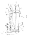
FIG. 5 is a perspective view showing the fixing bracket fixes the storage devices in a housing according to an embodiment of the disclosure.
DETAILED DESCRIPTION
Reference will now be made in detail to the present embodiments of the disclosure, examples of which are illustrated in the accompanying drawings. Wherever possible, the same reference numbers are used in the drawings and the description to refer to the same or like parts.
FIG. 1A is an exploded view of a fixing bracket 2 and storage devices 3 according to an embodiment of the disclosure. FIG. 1B is another exploded view of FIG. 1A.
As shown in FIG. 1A and FIG. 1B, the fixing bracket 2 is used to accommodate two storage devices 3. Each of the storage devices 3 has a first sidewall 30 a and a second sidewall 30 b that are opposite to each other. The first sidewall 30 a and the second sidewall 30 b of each of the storage devices 3 respectively have plurality of fixing holes 300. The fixing bracket 2 includes a frame body 20 and two pivotal members 22. The frame body 20 of the fixing bracket 2 has an opening 206 and an accommodating space S. The frame body 20 includes a plurality of first fixing pins 204 a in the accommodating space S.
In detail, the frame body 20 of the fixing bracket 2 includes a top board 200, a bottom board 202, a plurality of connecting ribs 201, and a backboard 204. The bottom board 202 of the frame body 20 is connected to the top board 200 by the connecting ribs 201, so that the bottom board 202 is parallel to the top board 200. Each of the pivotal members 22 is pivotally connected to the top board 200 and the bottom board 202 and is adjacent to the opening 206. The backboard 204 of the frame body 20 is connected between the top board 200 and the bottom board 202 and is opposite to the opening 206 (i.e., the backboard 204 is located away from the opening 206 and the pivotal members 22). The first fixing pins 204 a of the frame body 20 are disposed on the backboard 204.
FIG. 2 is a perspective view of the fixing bracket 2 and the storage devices 3 in FIG. 1A, in which pivotal members 22 open the opening 206. FIG. 3 is another perspective view of FIG. 2, in which the pivotal members 22 close parts of the opening 206.
As shown in FIG. 2 and FIG. 3, the storage devices 3 can be accommodated in the accommodating space S from the opening 206 of the frame body 20. Each of the first fixing pins 204 a on the backboard 204 is inserted into the corresponding fixing hole 300 on the first sidewall 30 a. The pivotal members 20 of the fixing bracket 2 are pivotally connected to the frame body 20, so as to rotate to open or cover parts of the opening 206 of the frame body 20. Each of the pivotal members 22 of the fixing bracket 2 includes a plurality of second fixing pins 224 a. When the pivotal members 22 of the fixing bracket 2 cover the parts of the opening 206 of the frame body 20, each of the second fixing pins 224 a on the pivotal members 22 is inserted into the corresponding fixing hole 300 on the second sidewall 30 b. In other words, after the storage devices 3 are accommodated in the frame body 20 of the fixing bracket 2 and the pivotal members 22 cover the parts of the opening 206 of the frame body 20, the first fixing pins 204 a disposed in the frame body 20 (particularly, disposed on the backboard 204) and the second fixing pins 224 a disposed on the pivotal members 22 are respectively inserted into the fixing holes 300 on the first sidewalls 30 a and the fixing holes 300 on the second sidewalls of the storage devices 3, so as to achieve the purpose of fixing the storage devices 3 in the fixing bracket 2.
It should be pointed out that the number of the storage devices 3 that are accommodated in the fixing bracket 2 of the disclosure is not limited in this regard and can be adjusted as needed, and the number of the first fixing pins 204 a disposed in the frame body 20 and the number of the second fixing pins 224 a disposed on the pivotal members 22 needs to be adjusted correspondingly.
In detail, the top board 200 of the frame body 20 includes two first engaging structures 200 a. The first engaging structures 200 a of the top board 200 are respectively adjacent to the pivotal members 22. The bottom board 202 of the frame body 20 includes two second engaging structures 202 a. The second engaging structures 202 a of the bottom board 202 are respectively adjacent to the pivotal members 22. Each of the pivotal members 22 of the fixing bracket 2 includes a first pivotal plate 220, a second pivotal plate 222, an axis 223 (e.g., 223 a and 223 b) that extends through connections (e.g., 223 a′ and 223 b′, respectively) of the top board 200, and a covering plate 224. Each of the first pivotal plates 220 of the pivotal members 22 is pivotally connected to the top board 200 and has a first engaging portion. Each of the second pivotal plates 222 of the pivotal members 22 is pivotally connected to the bottom board 202 and has a second engaging portion. Each of the covering plate 224 of the pivotal members 22 is connected between the corresponding first pivotal plate 220 and the corresponding second pivotal plate 222. The second fixing pins 224 a of the pivotal members 22 are disposed on the covering plates 224. When the covering plates rotate together with the first pivotal plates 220 and the second pivotal plates 222 to cover the parts of the opening 206, the covering plates 224 abuts against the top board 200 and the bottom board 202 of the frame body 20, each of the first engaging portions of the first pivotal plate 220 is engaged with the corresponding first engaging structure 200 a, and each of the second engaging portions of the second pivotal plate 222 is engaged with the corresponding second engaging structure 202 a.
Furthermore, the top board 200 of the frame body 20 further includes two first plate bodies. Each of the first engaging portions of the first pivotal plates 220 is a first hole 220 a. Each of the first engaging structures 200 a of the top board 200 includes a first elastic piece 200 a 1 and a first protrusion 200 a 2. The first elastic pieces 200 a 1 of the first engaging structures 200 a are connected to an edge of the first plate body. The first protrusions 200 a 2 of the first engaging structures 200 a are disposed at surfaces of the first elastic pieces 200 a 1 facing away from the accommodating space S. During the period that the pivotal members 22 cover toward the opening 206 of the frame body 20, each of the first pivotal plates 220 push the corresponding first protrusion 200 a 2 of the corresponding first engaging structure 200 a, so as to make the corresponding first elastic piece 200 a 1 move toward the accommodating space S. When the covering plates 224 abut against the top board 200 and the bottom board 202 of the frame body 20, each of the first elastic pieces 200 a 1 of the first engaging structures 200 a recover to make the corresponding first protrusion 200 a 2 be engaged with the corresponding first hole 220 a.
The bottom board 202 of the frame body 20 further includes two second plate bodies. Each of the second engaging portions of the second pivotal plates 222 is a second hole 222 a. Each of the second engaging structures 202 a of the bottom board 202 includes a second elastic piece 202 a 1 and a second protrusion 202 a 2. The second elastic pieces 202 a 1 of the second engaging structures 202 a are connected to an edge of the second plate body. The second protrusions 202 a 2 of the second engaging structures 202 a are disposed at surfaces of the second elastic pieces 202 a 1 facing away from the accommodating space S. During the period that the pivotal members 22 cover toward the opening 206 of the frame body 20, each of the second pivotal plates 222 push the corresponding second protrusion 202 a 2 of the corresponding second engaging structure 202 a, so as to make the corresponding second elastic piece 202 a 1 move toward the accommodating space S. When the covering plates 224 abut against the top board 200 and the bottom board 202 of the frame body 20, each of the second elastic pieces 202 a 1 of the second engaging structures 202 a recover to make the corresponding second protrusion 200 a 2 be engaged with the corresponding second hole 220 a.
Hence, when the pivotal members 22 of the fixing bracket 2 cover the parts of the opening 206 of the frame body 20, the first engaging portions (i.e., the first holes 220 a) and the second engaging portions (i.e., the second holes 222 a) on the pivotal members 22 are respectively engaged with the first engaging structures 200 a (i.e., the first protrusions 200 a 2) and the second engaging structures 202 a (i.e., the second protrusions 202 a 2), so as to prevent the problem that the pivotal members 22 unexpectedly open the opening 206 to make first fixing pins 204 a on the frame body 20 and the second fixing pins 224 a on the pivotal members 22 be unable to fix to the fixing holes 300 on the storage devices 3, and thus to prevent the storage devices 3 from leaving the frame body 20.
However, in order to achieve the purpose of engaging the pivotal members 22 to the frame body 20 when the pivotal members 22 cover the parts of the opening 206, in an embodiment of the disclosure, only the first engaging structures 200 a are disposed on the top board 200 of the frame body 20, and only the first engaging plates are disposed on the pivotal members 22 for engaged with the first engaging structures 200 a. Alternatively, in another embodiment of the disclosure, only the second engaging structures 202 a are disposed on the bottom board 202 of the frame body 20, and only the second engaging plates are disposed on the pivotal members 22 for engaged with the second engaging structures 202 a.
FIG. 4 is a front view of the fixing bracket 2 in FIG. 1A. FIG. 5 is a perspective view showing the fixing bracket 2 fixes the storage devices 3 in a housing 1 according to an embodiment of the disclosure.
As shown in FIG. 4 and FIG. 5, the bottom board 202 of the frame body 20 further includes a plurality of third engaging structures 202 b. The third engaging structures 202 b of the bottom board 202 are located at a surface of the bottom board 202 facing away from the accommodating space S to be engaged with chutes 10 on the housing 1. Hence, the fixing bracket 2 of the disclosure can achieve the purpose of rapidly fixing the storage devices 3 in the housing 1 without using screws.
It should be pointed out that the number of the third engaging structures 202 b included disposed on the bottom board 202 is not limited in this regard and can be adjusted as needed.
According to the foregoing recitations of the embodiments of the disclosure, it can be seen that the fixing bracket of the disclosure is capable of accommodating a plurality of storage devices. After the storage devices are accommodated in the fixing bracket and the pivotal members cover the parts of the opening of the frame body, the first fixing pins disposed on the frame body and the second fixing pins disposed on the pivotal members respectively insert into the fixing holes at two opposite sidewalls of the storage devices, so as to achieve the purpose of fixing the storage devices in the fixing bracket. Furthermore, when the pivotal members cover the parts of the opening, the engaging portions on the pivotal members are engaged with the engaging structures on the frame body, so as to prevent the problem that the pivotal members unexpectedly open the opening and thus let the storage devices to leave the frame body. Moreover, the fixing bracket of the disclosure further has an additional engaging structure disposed at the bottom of the frame body to be engaged with the chute of the housing, so as to achieve the purpose of rapidly fixing the storage devices in the housing without using screws.
It will be apparent to those skilled in the art that various modifications and variations can be made to the structure of the present disclosure without departing from the scope or spirit of the disclosure. In view of the foregoing, it is intended that the present disclosure cover modifications and variations of this disclosure provided they fall within the scope of the following claims.