US9837870B2 - Water-resistant motor and end bell - Google Patents
Water-resistant motor and end bell Download PDFInfo
- Publication number
- US9837870B2 US9837870B2 US14/818,529 US201514818529A US9837870B2 US 9837870 B2 US9837870 B2 US 9837870B2 US 201514818529 A US201514818529 A US 201514818529A US 9837870 B2 US9837870 B2 US 9837870B2
- Authority
- US
- United States
- Prior art keywords
- end bell
- seat
- motor
- shaft
- bearing
- Prior art date
- Legal status (The legal status is an assumption and is not a legal conclusion. Google has not performed a legal analysis and makes no representation as to the accuracy of the status listed.)
- Expired - Fee Related, expires
Links
- XLYOFNOQVPJJNP-UHFFFAOYSA-N water Substances O XLYOFNOQVPJJNP-UHFFFAOYSA-N 0.000 title claims abstract description 23
- 230000000717 retained effect Effects 0.000 claims description 6
- 230000004323 axial length Effects 0.000 claims description 3
- 230000015572 biosynthetic process Effects 0.000 abstract 1
- 239000007921 spray Substances 0.000 description 3
- 238000001816 cooling Methods 0.000 description 1
- 238000004804 winding Methods 0.000 description 1
Images


Classifications
-
- H—ELECTRICITY
- H02—GENERATION; CONVERSION OR DISTRIBUTION OF ELECTRIC POWER
- H02K—DYNAMO-ELECTRIC MACHINES
- H02K5/00—Casings; Enclosures; Supports
- H02K5/04—Casings or enclosures characterised by the shape, form or construction thereof
- H02K5/10—Casings or enclosures characterised by the shape, form or construction thereof with arrangements for protection from ingress, e.g. water or fingers
-
- H—ELECTRICITY
- H02—GENERATION; CONVERSION OR DISTRIBUTION OF ELECTRIC POWER
- H02K—DYNAMO-ELECTRIC MACHINES
- H02K5/00—Casings; Enclosures; Supports
- H02K5/04—Casings or enclosures characterised by the shape, form or construction thereof
- H02K5/16—Means for supporting bearings, e.g. insulating supports or means for fitting bearings in the bearing-shields
-
- H—ELECTRICITY
- H02—GENERATION; CONVERSION OR DISTRIBUTION OF ELECTRIC POWER
- H02K—DYNAMO-ELECTRIC MACHINES
- H02K2205/00—Specific aspects not provided for in the other groups of this subclass relating to casings, enclosures, supports
- H02K2205/09—Machines characterised by drain passages or by venting, breathing or pressure compensating means
Definitions
- the invention relates generally to electric motors and more particularly to water-resistant motors.
- Electric motors are often used on machines that require a washdown. Sometimes the motors themselves are subjected to powerful sprays that can force water into the motor through any opening in the housing. As shaft seals and seals at the seams of between housing sections wear, the motors become more susceptible to water intrusion. When a hot motor is washed down, the water spray cools the motor. The cooling can cause the air pressure in voids inside the motor to drop. The drop in air pressure in these voids sucks water into the motor. The water that is sucked in can then cause electrical short circuits and motor failure.
- One version of a water-resistant motor embodying features of the invention comprises a motor housing that surrounds an interior region and has an open end.
- An end bell attached to the motor housing closes the open end.
- a shaft extends axially outward from the interior region through a central bore in the end bell.
- the shaft has a bearing region and a seal region axially outward of the bearing region.
- a rotary bearing attached to the shaft in the bearing region is retained by the end bell.
- the end bell also retains a seal that contacts the shaft in the seal region.
- a gap is formed between the rotary bearing and the seal.
- the end bell has a passage that extends from the interior region of the motor housing to the gap. The passage bypasses the rotary bearing.
- a vent extends from outside the motor housing through the end bell or the motor housing itself into communication with the interior region and the passage to maintain air pressure at atmosphere or higher in the gap.
- one version of a motor end bell embodying features of the invention comprises an end face extending radially inward from an outer circumference to a central bore, which defines an axis for a shaft received in the bore.
- a hub extends axially from the end face to an inner end.
- the hub defines the central bore.
- the hub includes a bearing seat bounding a portion of the central bore.
- the bearing seat has a groove that extends the axial length of the bearing seat to the inner end of the hub.
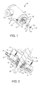
- FIG. 1 is an isometric view, partly exploded, of an electric motor embodying features of the invention
- FIG. 2 is a cross section of an end portion of the motor of FIG. 1 viewed along lines 2 - 2 ;
- FIG. 3 is an isometric view of the end bell of the motor of FIG. 1 ;
- FIG. 4 is a schematic cross section of the bearing region of FIG. 2 .
- FIG. 1 A water-resistant electric motor embodying features of the invention is shown in FIG. 1 .
- the motor 10 has a motor housing 12 , in this example a cylindrical tube having an open end 14 .
- a drive shaft 16 having an axis 18 extends axially outward of the motor housing 12 through a central bore 19 in an end bell 20 .
- the end bell 20 is bolted to the motor housing 12 to close the open end 14 .
- a splash shield 22 is retained in place on the shaft 16 near the end bell 20 by a shaft retainer, such as a snap ring 24 .
- the splash shield deflects water spray away from the shaft 16 and the bore 19 .
- Electric wires are connected to motor windings in a wiring compartment 26 that opens through the housing 12 into the interior of the motor.
- An air-pressure fitting 28 fits in a vent 30 that extends through the end bell 20 into the interior of the motor.
- the vent could be formed in the motor housing 12 .
- the motor housing 12 surrounds an interior region 32 of the motor.
- the stator 34 and the rotor 36 reside in the interior region 32 .
- the shaft 16 extends from the rotor 36 through the central bore 19 axially outward of the end bell 20 .
- the shaft has a bearing region 38 at which a rotary bearing 40 is attached.
- the shaft 16 has a seal region 42 axially outward of the bearing region 38 .
- One or more seals 44 contact the shaft 16 in the seal region 42 .
- the seal 44 and the rotary bearing 40 are retained in the end bell 20 .
- a gap 46 is formed between the seal 44 and the rotary bearing 40 .
- a passage 48 is formed in the end bell 20 .
- the passage 48 bypasses the rotary bearing 40 and puts the gap 48 in communication with the interior region 32 of the motor and, via the vent 30 , through a tube or other sheltered passageway to the external atmosphere or through the fitting 28 to a source of high-pressure air or other gas. In this way, the air pressure in the gap is maintained at or above atmospheric pressure to prevent the suctioning of water through the seal 44 and the rotary bearing 40 into the interior region 32 of the motor 10 .
- the passage 48 in the end bell 20 is better shown in FIG. 3 .
- the end bell 20 has an end face 50 (also in FIG. 2 ) that extends radially from an outer circumference 52 to the central bore 19 , which defines the axis 18 for the shaft.
- An outer shell 54 extends axially from the outer circumference 52 of the end face 50 .
- a hub 56 extends axially from the end face 50 to an inner end 58 .
- the hub 56 defines the central bore 19 .
- the hub 56 has a bearing seat 60 on which the rotary bearing sits.
- the passage 48 is formed in the bearing seat 60 by a groove extending the axial length of the bearing seat to the inner end 58 of the hub 56 .
- the hub 56 also has a seal seat 62 axially outward of the bearing seat 60 .
- the diameter d of the seal seat 62 is less than the diameter D of the bearing seat 60 . So a shoulder 64 is formed at their interface.
- the rotary bearing 40 rests against the shoulder 64 . But the passage 48 extends through the shoulder (as shown at 66 ) to reach the gap 46 .
- the splash shield 22 is retained on the shaft 16 by the snap ring 24 .
- a tab 68 extends radially outward and axially inward from the periphery of the ring to snap into a hole forming a receptacle 70 in the splash shield 22 . Because the snap ring 24 fits tight on the shaft 16 , the engagement of the tab 68 with the wall of the receptacle 70 causes the splash shield 22 to rotate with the shaft. The rotation of the splash shield 22 flings sprayed water outward away from the rotating shaft 16 .
Landscapes
- Engineering & Computer Science (AREA)
- Power Engineering (AREA)
- Motor Or Generator Frames (AREA)
Abstract
Description
Claims (14)
Priority Applications (1)
| Application Number | Priority Date | Filing Date | Title |
|---|---|---|---|
| US14/818,529 US9837870B2 (en) | 2014-11-25 | 2015-08-05 | Water-resistant motor and end bell |
Applications Claiming Priority (2)
| Application Number | Priority Date | Filing Date | Title |
|---|---|---|---|
| US201462084364P | 2014-11-25 | 2014-11-25 | |
| US14/818,529 US9837870B2 (en) | 2014-11-25 | 2015-08-05 | Water-resistant motor and end bell |
Publications (2)
| Publication Number | Publication Date |
|---|---|
| US20160149460A1 US20160149460A1 (en) | 2016-05-26 |
| US9837870B2 true US9837870B2 (en) | 2017-12-05 |
Family
ID=56011189
Family Applications (1)
| Application Number | Title | Priority Date | Filing Date |
|---|---|---|---|
| US14/818,529 Expired - Fee Related US9837870B2 (en) | 2014-11-25 | 2015-08-05 | Water-resistant motor and end bell |
Country Status (1)
| Country | Link |
|---|---|
| US (1) | US9837870B2 (en) |
Cited By (2)
| Publication number | Priority date | Publication date | Assignee | Title |
|---|---|---|---|---|
| US20260035183A1 (en) * | 2024-08-02 | 2026-02-05 | Nordstrong Equipment Limited | End bell for belt conveyor idler assembly |
| US12580440B2 (en) | 2023-06-08 | 2026-03-17 | Enedym Inc. | Motor housing design for rotor-axial-displacement-independent and mounting-orientation-independent ingress protection |
Families Citing this family (2)
| Publication number | Priority date | Publication date | Assignee | Title |
|---|---|---|---|---|
| EP3282561B1 (en) * | 2016-06-27 | 2019-02-27 | Robert Bosch Gmbh | Electrical machine and method for manufacturing an electrical machine |
| IT201900005074A1 (en) * | 2019-04-04 | 2020-10-04 | Spal Automotive Srl | ROTATING ELECTRIC MACHINE. |
Citations (12)
| Publication number | Priority date | Publication date | Assignee | Title |
|---|---|---|---|---|
| US4086507A (en) * | 1975-02-03 | 1978-04-25 | Lockwood Corporation | Outdoor motor enclosure |
| US4186319A (en) * | 1977-04-26 | 1980-01-29 | General Electric Company | Dynamoelectric machine end shield |
| US5127148A (en) * | 1989-10-26 | 1992-07-07 | A. O. Smith Corporation | Method of fabricating a dynameoelectric machine |
| US5412272A (en) * | 1994-01-24 | 1995-05-02 | Mensching; Herman E. | Submersible explosion proof electric brake motor |
| US6188156B1 (en) * | 1999-11-01 | 2001-02-13 | Emerson Electric Co. | Cast rabbet joint for proper alignment of assembled components |
| US7420302B2 (en) * | 2005-05-31 | 2008-09-02 | Regal-Beloit Corporation | Mid shield bearing support of an electric motor |
| JP5044164B2 (en) | 2006-08-11 | 2012-10-10 | 株式会社ミツバ | Motor equipment |
| US8410643B2 (en) * | 2010-07-22 | 2013-04-02 | Globe Motors, Inc. | Frameless electric motor assembly |
| US8482173B2 (en) * | 2009-01-14 | 2013-07-09 | Regal Beloit America, Inc. | End shield and inner bearing cap assembly |
| US8749110B2 (en) * | 2009-12-11 | 2014-06-10 | Johnson Electric S.A. | Permanent magnet motor |
| JP2014110697A (en) | 2012-12-03 | 2014-06-12 | Mitsuba Corp | Electric motor |
| JP5547783B2 (en) | 2012-09-27 | 2014-07-16 | 株式会社小松製作所 | Electric motor and its cooling water circuit |
-
2015
- 2015-08-05 US US14/818,529 patent/US9837870B2/en not_active Expired - Fee Related
Patent Citations (12)
| Publication number | Priority date | Publication date | Assignee | Title |
|---|---|---|---|---|
| US4086507A (en) * | 1975-02-03 | 1978-04-25 | Lockwood Corporation | Outdoor motor enclosure |
| US4186319A (en) * | 1977-04-26 | 1980-01-29 | General Electric Company | Dynamoelectric machine end shield |
| US5127148A (en) * | 1989-10-26 | 1992-07-07 | A. O. Smith Corporation | Method of fabricating a dynameoelectric machine |
| US5412272A (en) * | 1994-01-24 | 1995-05-02 | Mensching; Herman E. | Submersible explosion proof electric brake motor |
| US6188156B1 (en) * | 1999-11-01 | 2001-02-13 | Emerson Electric Co. | Cast rabbet joint for proper alignment of assembled components |
| US7420302B2 (en) * | 2005-05-31 | 2008-09-02 | Regal-Beloit Corporation | Mid shield bearing support of an electric motor |
| JP5044164B2 (en) | 2006-08-11 | 2012-10-10 | 株式会社ミツバ | Motor equipment |
| US8482173B2 (en) * | 2009-01-14 | 2013-07-09 | Regal Beloit America, Inc. | End shield and inner bearing cap assembly |
| US8749110B2 (en) * | 2009-12-11 | 2014-06-10 | Johnson Electric S.A. | Permanent magnet motor |
| US8410643B2 (en) * | 2010-07-22 | 2013-04-02 | Globe Motors, Inc. | Frameless electric motor assembly |
| JP5547783B2 (en) | 2012-09-27 | 2014-07-16 | 株式会社小松製作所 | Electric motor and its cooling water circuit |
| JP2014110697A (en) | 2012-12-03 | 2014-06-12 | Mitsuba Corp | Electric motor |
Cited By (3)
| Publication number | Priority date | Publication date | Assignee | Title |
|---|---|---|---|---|
| US12580440B2 (en) | 2023-06-08 | 2026-03-17 | Enedym Inc. | Motor housing design for rotor-axial-displacement-independent and mounting-orientation-independent ingress protection |
| US20260035183A1 (en) * | 2024-08-02 | 2026-02-05 | Nordstrong Equipment Limited | End bell for belt conveyor idler assembly |
| US12595132B2 (en) * | 2024-08-02 | 2026-04-07 | Nordstrong Equipment Limited | End bell for belt conveyor idler assembly |
Also Published As
| Publication number | Publication date |
|---|---|
| US20160149460A1 (en) | 2016-05-26 |
Similar Documents
| Publication | Publication Date | Title |
|---|---|---|
| US9837870B2 (en) | Water-resistant motor and end bell | |
| US20180278117A1 (en) | Electric motor | |
| US9859672B2 (en) | Electric machine and connecting unit for an electric machine | |
| EP3125410B1 (en) | Totally enclosed main electric motor | |
| WO2014072318A3 (en) | Separator with direct drive | |
| WO2010112864A3 (en) | A rotating machine with shaft sealing arrangement | |
| CN105281476B (en) | Motor | |
| US20200198667A1 (en) | Covering system for wheelset shafts of rail vehicles | |
| RU2006130852A (en) | DRIVE UNIT WITH CABLE CONNECTOR | |
| US20130272853A1 (en) | Compressor | |
| CN102484407A (en) | Explosion-proof motors | |
| CA3080479A1 (en) | Electrical discharge prevention in bearing for submersible pump motor | |
| US20140312723A1 (en) | Electric motor for vehicle | |
| CN105042310A (en) | Rotating machine | |
| CN209354662U (en) | Labyrinth ring | |
| CN109639040B (en) | Motor and main shaft protection structure | |
| US10780542B2 (en) | Motor and spindle protection structure | |
| CN215817715U (en) | Inner rotor motor with fixed motor outgoing line fixing structure and fixed rotating shaft | |
| CN107681809B (en) | Sealing device suitable for mowing motor, mowing motor and mowing machine | |
| JPWO2016166899A1 (en) | Motor with static pressure seal | |
| CN109818445B (en) | Motor and machine tool | |
| CN104329379B (en) | A kind of dirt-proof bearing | |
| CN209389822U (en) | A kind of structure that internal rotor cooling air is drawn to cooling radial direction magnetic bearing | |
| KR20180115231A (en) | Hydraulic rotational drive | |
| JP3101419U (en) | Rotating machine |
Legal Events
| Date | Code | Title | Description |
|---|---|---|---|
| AS | Assignment |
Owner name: LAITRAM, L.L.C., LOUISIANA Free format text: ASSIGNMENT OF ASSIGNORS INTEREST;ASSIGNOR:GREVE, CHRISTOPHER G.;REEL/FRAME:036258/0414 Effective date: 20141125 |
|
| STCF | Information on status: patent grant |
Free format text: PATENTED CASE |
|
| FEPP | Fee payment procedure |
Free format text: MAINTENANCE FEE REMINDER MAILED (ORIGINAL EVENT CODE: REM.); ENTITY STATUS OF PATENT OWNER: LARGE ENTITY |
|
| LAPS | Lapse for failure to pay maintenance fees |
Free format text: PATENT EXPIRED FOR FAILURE TO PAY MAINTENANCE FEES (ORIGINAL EVENT CODE: EXP.); ENTITY STATUS OF PATENT OWNER: LARGE ENTITY |
|
| STCH | Information on status: patent discontinuation |
Free format text: PATENT EXPIRED DUE TO NONPAYMENT OF MAINTENANCE FEES UNDER 37 CFR 1.362 |
|
| FP | Lapsed due to failure to pay maintenance fee |
Effective date: 20211205 |