US9837833B2 - Discharge balancing device, discharge balancing method, and power supply system - Google Patents
Discharge balancing device, discharge balancing method, and power supply system Download PDFInfo
- Publication number
- US9837833B2 US9837833B2 US14/474,175 US201414474175A US9837833B2 US 9837833 B2 US9837833 B2 US 9837833B2 US 201414474175 A US201414474175 A US 201414474175A US 9837833 B2 US9837833 B2 US 9837833B2
- Authority
- US
- United States
- Prior art keywords
- energy storage
- electric energy
- unit
- units
- storage units
- Prior art date
- Legal status (The legal status is an assumption and is not a legal conclusion. Google has not performed a legal analysis and makes no representation as to the accuracy of the status listed.)
- Active, expires
Links
Images


Classifications
-
- H02J7/0021—
-
- H—ELECTRICITY
- H02—GENERATION; CONVERSION OR DISTRIBUTION OF ELECTRIC POWER
- H02J—ELECTRIC POWER NETWORKS; CIRCUIT ARRANGEMENTS OR SYSTEMS FOR SUPPLYING OR DISTRIBUTING ELECTRIC POWER; SYSTEMS FOR STORING ELECTRIC ENERGY
- H02J7/00—Circuit arrangements for charging or discharging batteries or for supplying loads from batteries
- H02J7/50—Circuit arrangements for charging or discharging batteries or for supplying loads from batteries acting upon multiple batteries simultaneously or sequentially
- H02J7/52—Circuit arrangements for charging or discharging batteries or for supplying loads from batteries acting upon multiple batteries simultaneously or sequentially for charge balancing, e.g. equalisation of charge between batteries
- H02J7/54—Passive balancing, e.g. using resistors or parallel MOSFETs
-
- H02J7/0016—
-
- H—ELECTRICITY
- H02—GENERATION; CONVERSION OR DISTRIBUTION OF ELECTRIC POWER
- H02J—ELECTRIC POWER NETWORKS; CIRCUIT ARRANGEMENTS OR SYSTEMS FOR SUPPLYING OR DISTRIBUTING ELECTRIC POWER; SYSTEMS FOR STORING ELECTRIC ENERGY
- H02J7/00—Circuit arrangements for charging or discharging batteries or for supplying loads from batteries
- H02J7/80—Circuit arrangements for charging or discharging batteries or for supplying loads from batteries including monitoring or indicating arrangements
- H02J7/82—Control of state of charge [SOC]
Definitions
- the present invention relates to a discharge balancing device, a discharge balancing method and a power supply system, and more particularly, to a discharge balancing device, a discharge balancing method, and a power supply system capable of performing discharge balancing according to capacities of electric energy storage units.
- a portable electronic device such as a smart phone, a notebook, a tablet computer, etc.
- the rechargeable battery is composed of a plurality of electric energy storage units. It is unavoidable that different electric energy storage units have different statuses, which may result in reliability issues. For example, given the fact that some of the electric energy storage units have higher internal resistances due to defects (such as manufacturing variation) and/or utility conditions (such as charging/discharging times), when the electric energy storage units are connected in series, the electric energy storage units having higher internal resistances are forced to consume more power than the others, causing the electric energy storage units having higher internal resistances to be deteriorated faster than the others. Once an electric energy storage unit having a higher internal resistance depletes, the entire battery fails to provide electric power, even some well-condition electric energy storage units are contained in the battery, causing a waste of resources.
- the invention discloses a discharge balancing device, for balancing a plurality of electric energy storage units connected in series in a discharge stage, comprising a plurality of bypass units, respectively connected to the plurality of electric energy storage units in parallel, configured to drain bypass currents from the plurality of electric energy storage units according to control signals; an energy condition measurement circuit, coupled to the plurality of the electric energy storage units, configured to measure energy conditions of the plurality of electric energy storage units; and a balancing control unit, coupled to the energy condition measurement circuit and the plurality of bypass units, configured to generate each of the control signals according to the energy conditions measured by the energy condition measurement circuit, so as to control each of the plurality of bypass units whether to drain a bypass current from a corresponding electric energy storage unit.
- the invention further discloses a discharge balancing method, for balancing a plurality of electric energy storage units connected in series in a discharge stage, the discharge balancing method comprising measuring energy conditions of the plurality of electric energy storage units; and controlling each of the plurality of bypass units whether to drain a bypass current from a corresponding electric energy storage unit according to the measured energy conditions.
- the invention further discloses an power supply system, comprising a plurality of electric energy storage units, connected in series; and a discharge balancing device, coupled to the plurality of electric energy storage units, for balancing the plurality of electric energy storage units in a discharge stage, the discharge balancing device comprising a plurality of bypass units, respectively connected to the plurality of electric energy storage units in parallel, configured to drain bypass currents from the plurality of electric energy storage units according to control signals; an energy condition measurement circuit, coupled to the plurality of the electric energy storage units, configured to measure energy conditions of the plurality of electric energy storage units; and a balancing control unit, coupled to the energy condition measurement circuit and the plurality of bypass units, configured to generate each of the control signals according to the energy conditions measured by the energy condition measurement circuit, so as to control each of the plurality of bypass units whether to drain a bypass current from a corresponding electric energy storage unit.
- the invention further discloses a discharge balancing device, for balancing a plurality of electric energy storage units connected in series in a discharge stage, comprising a plurality of switch units, connected in series and parallel to the plurality of electric energy storage units, each configured to be conducted according to control signals; a plurality of impedance units, each having one terminal electrically connected to adjacent electric energy storage units of plurality of electric energy storage units and another terminal electrically connected to adjacent switch units of the plurality of switch units; an energy condition measurement circuit, coupled to the plurality of the electric energy storage units, configured to measure energy conditions of the plurality of electric energy storage units; and a balancing control unit, coupled to the energy condition measurement circuit and the plurality of switch units, configured to generate each of the control signals according to the energy conditions measured by the energy condition measurement circuit, so as to control each of the plurality of switch units whether to drain a bypass current from a corresponding electric energy storage unit.
- the invention further discloses an power supply system, comprising a plurality of electric energy storage units, connected in series; and a discharge balancing device, coupled to the plurality of electric energy storage units, for balancing the plurality of electric energy storage units in a discharge stage, the discharge balancing device comprising a plurality of switch units, connected in series and parallel to the plurality of electric energy storage units, each configured to be conducted according to control signals; a plurality of impedance units, each having one terminal electrically connected to adjacent electric energy storage units of plurality of electric energy storage units and another terminal electrically connected to adjacent switch units of the plurality of switch units; an energy condition measurement circuit, coupled to the plurality of the electric energy storage units, configured to measure energy conditions of the plurality of electric energy storage units; and a balancing control unit, coupled to the energy condition measurement circuit and the plurality of switch units, configured to generate each of the control signals according to the energy conditions measured by the energy condition measurement circuit, so as to control each of the plurality of switch units whether to drain a bypass current from a
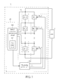
- FIG. 1 is a schematic diagram of a power supply system according to an embodiment of the invention.
- FIG. 2 is a schematic diagram of a bypass unit according to an embodiment of the invention.
- FIG. 3 is a schematic diagram of a discharge balancing process according to an embodiment of the invention.
- FIG. 4 is a schematic diagram of an impedance unit according to an embodiment of the invention.
- FIG. 5 is a schematic diagram of an impedance unit according to an embodiment of the invention.
- FIG. 6 is a schematic diagram of a power supply system according to another embodiment of the invention.
- a method for balancing the electric energy storage units is balancing discharging operations of the electric energy storage units according to voltage values of the electric energy storage units.
- voltage and capacity of an electric energy storage unit may have a nonlinear relationship, which means that two electric energy storage units within the rechargeable battery may have a negligible voltage difference in between even a capacity difference in between is observable.
- the present invention performs balancing according to capacities of the electric energy storage units.
- FIG. 1 is a schematic diagram of a power supply system 1 according to an embodiment of the present invention.
- the power supply system 1 comprises a battery pack 12 and a discharge balancing device 10 , and provides electric power to a load 2 .
- the battery pack 12 comprises a plurality of electric energy storage units ES_ 1 -ES_n, which are connected in series. Each of the energy storage units may comprise at least a battery cell, and the at least a battery cell within an energy storage unit may be connected in series or in parallel, not limited herein.
- the discharge balancing device 10 comprises a plurality of bypass units BP_ 1 -BP_n, an energy condition measurement circuit 100 and a balancing control unit 102 .
- the bypass units BP_ 1 -BP_n are connected to the electric energy storage units ES_ 1 -ES_n in parallel, respectively. Each of the bypass units BP_ 1 -BP_n is configured to drain a bypass current from the corresponding electric energy storage units ES_ 1 -ES_n according to control signals CTL_ 1 -CTL_n. Take the bypass unit BP_ 1 as an example, the bypass unit BP_ 1 is connected to the energy storage unit ES_ 1 in parallel, and is configured to drain a bypass current from the energy storage unit ES_ 1 according to the control signal CTL_ 1 .
- the energy condition measurement circuit 100 is coupled to the electric energy storage units ES_ 1 -ES_n, for measuring energy conditions of the electric energy storage units ES_ 1 -ES_n.
- An energy condition of an electric energy storage unit may be a measured voltage value, a measured capacity, etc., of the electric energy storage unit.
- the balancing control unit 102 are coupled to the energy condition measurement circuit 100 and the bypass units BP_ 1 -BP_n, and configured to generate the control signals CTL_ 1 -CTL_n according to the energy conditions measured by the energy condition measurement circuit 100 , so as to control each of the bypass units BP_ 1 -BP_n whether to drain a bypass current from the corresponding electric energy storage unit.
- the energy condition measurement circuit 100 comprises a gas gauge circuit 104 , for measuring a capacity of each of the electric energy storage units ES_ 1 -ES_n, and sends information of the capacities of the electric energy storage units ES_ 1 -ES_n to the balancing control unit 100 .
- the balancing control unit 100 generates the control signals CTL_ 1 -CTL_n according to the capacities of the electric energy storage units ES_ 1 -ES_n, to instruct each of the bypass units BP_ 1 -BP_n whether or not to drain a bypass current from the corresponding electric energy storage unit for a period of time.
- the balancing control unit 102 generates the control signal CTL_x to configure the bypass units BP_x to drain a bypass current from the electric energy storage unit ES_x.
- the discharging rate of the electric energy storage unit ES_x is higher than the discharging rates of the rest of the electric energy storage units ES_ 1 -ES_n.
- the energy conditions for the balancing control unit 102 are the measured capacities of the electric energy storage units, and the balancing discharging operations of the electric energy storage units are based on the capacities of the electric energy storage units. Since the capacity differences of the electric energy storage units are more observable, the balancing discharging operations may be started earlier. Thus, it would have sufficient time to discharge the electric energy storage unit having the largest capacity by raising its discharging rate, allowing the electric energy storage unit balancing performed properly, such that the life of the battery pack 12 is lengthened.
- FIG. 2 is a schematic diagram of a bypass unit BP_k of the bypass units BP_ 1 -BP_n according to an embodiment of the present invention.
- each of the bypass units BP_ 1 -BP_n say, the bypass unit BP_k, comprises an impedance unit IMP_k and a switch unit SW_k, wherein the impedance unit IMP_k and the switch unit SW_k are connected in series.
- the switch unit SW_k can be a voltage controlled switch, such as a bipolar junction transistor (BJT), a field effect transistor (FET), etc.
- the switch unit SW_k receiving the control signal CTL_k, is configured to conduct a bypass current I_k accordingly.
- a magnitude of the bypass current I_k is determined by the impedance unit IMP_k.
- the impedance unit IMP_k may be a fixed resistor, a variable resistor, a voltage controlled resistor, etc.
- the balancing control unit 102 decides that the bypass current I_k should be drained from the corresponding electric energy storage unit ES_k, the balancing control unit 102 generates a control signal CTL_k to turn on the switch unit SW_k, conducting the bypass current I_k. Otherwise, the switch unit SW_k remains off, meaning that the bypass unit is cut off and conducts no current.
- the method of the discharge balancing device 10 balancing the electric energy storage units ES_ 1 -ES_n can be further summarized into a discharge balancing process 30 .
- the discharge balancing process 30 is executed by the discharge balancing device 10 .
- the discharge balancing process 30 comprises following steps:
- Step 300 Start.
- Step 302 The energy condition measurement circuit 100 measures the capacities of the electric energy storage units ES_ 1 -ES_n.
- Step 304 The balancing control unit 102 determines whether a capacity difference between a largest capacity and a lowest capacity of the electric energy storage units ES_ 1 -ES_n is greater than a predefined value. If the capacity difference is greater than the predefined value, proceed to Step 306 ; otherwise, proceed to Step 308 .
- Step 306 The balancing control unit 102 generates the control signals CTL_ 1 -CTL_n to control the bypass units BP_ 1 -BP_n corresponding to the electric energy storage unit which has the largest capacity among the electric energy storage units ES_ 1 -ES_n to drain a bypass current from the corresponding electric energy storage unit.
- Step 308 End.
- the discharge balancing device 10 may generate the control signals CTL_ 1 -CTL_n, and instruct each of the bypass units BP_ 1 -BP_n whether or not to drain the bypass current from the corresponding electric energy storage unit, so as to adjust the discharging rates of the electric energy storage units ES_ 1 -ES_n according to the capacities, alleviating a deterioration toward depletion of aged or ill-condition electric energy storage unit.
- a determination criterion is set in Step 304 to determine whether or not to proceed with the discharge balancing process 30 .
- the discharge balancing process 30 proceeds if the capacity difference between the largest capacity and the lowest capacity of the electric energy storage units ES_ 1 -ES_n is greater than the predefined value. Otherwise, if the capacity difference between the largest and the lowest capacities is smaller than the predefined value, meaning that the electric energy storage units ES_ 1 -ES_n are in a balanced status, then there is no need to proceed with the discharge balancing process 30 .
- the balancing control unit 102 determines the electric energy storage unit, e.g. ES_x, which has the largest capacity among the electric energy storage units ES_ 1 -ES_n. The balancing control unit 102 then generates the control signal CTL_x to turn on the switch unit SW_x, to drain the bypass current I_x from the electric energy storage unit ES_x. Meanwhile, the rest of the bypass units BP_ 1 -BP_n remain cut off.
- the electric energy storage unit e.g. ES_x
- the balancing control unit 102 determines whether to proceed with discharge balancing process 30 according to the capacity difference between the largest capacity and the lowest capacity of the electric energy storage units ES_ 1 -ES_n.
- the balancing control unit 102 may determine whether to proceed with the discharge balancing process 30 according to the capacity difference between the largest capacity and an average of the capacities of the electric energy storage units ES_ 1 -ES_n, which is not limited herein.
- balancing among electric energy storage units ES_ 1 -ES_n is to drain a bypass current for a discharge balancing period.
- the discharge balancing period is predefined.
- the discharge balancing process 30 is executed periodically with the constant predefined period.
- the discharge balancing process 30 may be performed repeatedly with variable balancing periods, and the variable balancing periods may depend on a capacity difference between the largest and the lowest capacities of the electric energy storage units ES_ 1 -ES_n, which can be modified accordingly and not limited herein.
- FIG. 4 is a schematic diagram of an impedance unit 40 according to an embodiment of the present invention.
- the impedance unit 40 comprises a selection unit 400 and a plurality of resistors R_ 1 -R_j, wherein the resistors R_ 1 -R_j have various resistance values.
- the selection unit 400 receives a control signal CTL generated by the balancing control unit 102 , to select a resistor from the resistors R_ 1 -R_j according to the control signal CTL.
- an impedance value of the impedance unit 40 is changeable according to the control signal CTL, for adaptively adjusting a discharging rate of the corresponding bypass unit.
- the impedance unit 40 can be applied to the impedance units IMP_ 1 -IMP_n of the bypass units BP_ 1 -NP_n in FIG. 1B .
- FIG. 5 is a schematic diagram of an impedance unit 50 according to an embodiment of the present invention. As shown in FIG.
- the impedance unit 50 comprises a plurality of resistors R_ 1 ′-R_j′ connected in series. Each of the resistors R_ 1 ′-R_j′ is connected to a decision unit D in parallel.
- the decision unit D receives a control signal CTL′, to be turned on, shorting two terminals of the resistor, or be cut off according to the control signal CTL′.
- an impedance value of the impedance unit 50 is changeable according to the control signal CTL′, for adaptively adjusting a discharging rate of the corresponding bypass unit.
- the impedance unit 50 can be applied to the impedance units IMP_ 1 -IMP_n of the bypass units BP_ 1 -NP_n in FIG. 1B .
- FIG. 1 is an embodiment of the present invention.
- the connecting method between the impedance units and the switch units as shown in FIG. 2 may be modified.
- FIG. 6 is a schematic diagram of a power supply system 6 according to an embodiment of the present invention.
- the structure of the power supply system 6 is similar to that of the power supply system 1 with bypass unit implementation shown in FIG. 2 , and thus, the same units are denoted by the same symbols.
- the difference between the power supply system 6 and the power supply system 1 is the connecting method between the impedance units and the switch units. As shown in FIG.
- the switch units SW_ 1 -SW_n are connected in series and parallel to the electric energy storage units ES_ 1 -ES_n.
- One terminal of each of the impedance units IMP_ 1 -IMP_n is connected between adjacent electric energy storage units, and another terminal thereof is connected between adjacent switch units.
- Each of the switch units SW_ 1 -SW_n is configured to be conducted according to the control signals CTL_ 1 -CTL_n generated by the balancing control unit 102 .
- Operating principles of the power supply system 6 are similar to those of the power supply system 1 , and can be referred to the relative paragraphs stated above, which are not narrated herein for brevity.
- the discharge balancing device of the present invention utilizes the gas gauge circuit for measuring the capacities of the electric energy storage units, and drains the bypass current according to the capacities of the electric energy storage units, thus avoiding the ill electric energy storage unit depleting faster problem. Therefore, the discharge balancing device of the present invention lengthens the life of the battery pack.
Landscapes
- Engineering & Computer Science (AREA)
- Power Engineering (AREA)
- Charge And Discharge Circuits For Batteries Or The Like (AREA)
Abstract
Description
Claims (32)
Priority Applications (1)
| Application Number | Priority Date | Filing Date | Title |
|---|---|---|---|
| US14/474,175 US9837833B2 (en) | 2014-08-31 | 2014-08-31 | Discharge balancing device, discharge balancing method, and power supply system |
Applications Claiming Priority (1)
| Application Number | Priority Date | Filing Date | Title |
|---|---|---|---|
| US14/474,175 US9837833B2 (en) | 2014-08-31 | 2014-08-31 | Discharge balancing device, discharge balancing method, and power supply system |
Publications (2)
| Publication Number | Publication Date |
|---|---|
| US20160064968A1 US20160064968A1 (en) | 2016-03-03 |
| US9837833B2 true US9837833B2 (en) | 2017-12-05 |
Family
ID=55403645
Family Applications (1)
| Application Number | Title | Priority Date | Filing Date |
|---|---|---|---|
| US14/474,175 Active 2035-10-12 US9837833B2 (en) | 2014-08-31 | 2014-08-31 | Discharge balancing device, discharge balancing method, and power supply system |
Country Status (1)
| Country | Link |
|---|---|
| US (1) | US9837833B2 (en) |
Cited By (1)
| Publication number | Priority date | Publication date | Assignee | Title |
|---|---|---|---|---|
| TWI818593B (en) * | 2022-06-20 | 2023-10-11 | 新盛力科技股份有限公司 | Discharge balancing method for battery equipment |
Families Citing this family (5)
| Publication number | Priority date | Publication date | Assignee | Title |
|---|---|---|---|---|
| US10680450B2 (en) * | 2015-10-05 | 2020-06-09 | Lenovo (Singapore) Pte. Ltd. | Devices and methods to discharge battery |
| EP3398239A1 (en) * | 2015-12-29 | 2018-11-07 | Vito NV | Device and method for the reconfiguration of a rechargeable energy storage device into separate battery connection strings |
| CN107251363B (en) * | 2015-12-31 | 2020-09-29 | 深圳市大疆创新科技有限公司 | Method and system for balancing battery assemblies |
| US10819122B2 (en) | 2018-04-05 | 2020-10-27 | Lenovo (Singapore) Pte. Ltd. | Systems and methods to use cell balancing resistor(s) of battery pack to reduce charge level of battery cells |
| US11429167B2 (en) | 2020-07-17 | 2022-08-30 | Lenovo (Singapore) Pte. Ltd. | Techniques to decommission battery based on user command |
Citations (1)
| Publication number | Priority date | Publication date | Assignee | Title |
|---|---|---|---|---|
| US20120086399A1 (en) * | 2010-10-12 | 2012-04-12 | Samsung Sdi Co., Ltd. | Battery pack, method of controlling the same, and energy storage system including the battery pack |
-
2014
- 2014-08-31 US US14/474,175 patent/US9837833B2/en active Active
Patent Citations (1)
| Publication number | Priority date | Publication date | Assignee | Title |
|---|---|---|---|---|
| US20120086399A1 (en) * | 2010-10-12 | 2012-04-12 | Samsung Sdi Co., Ltd. | Battery pack, method of controlling the same, and energy storage system including the battery pack |
Cited By (1)
| Publication number | Priority date | Publication date | Assignee | Title |
|---|---|---|---|---|
| TWI818593B (en) * | 2022-06-20 | 2023-10-11 | 新盛力科技股份有限公司 | Discharge balancing method for battery equipment |
Also Published As
| Publication number | Publication date |
|---|---|
| US20160064968A1 (en) | 2016-03-03 |
Similar Documents
| Publication | Publication Date | Title |
|---|---|---|
| US9837833B2 (en) | Discharge balancing device, discharge balancing method, and power supply system | |
| US9300159B2 (en) | Charging method for a rechargeable battery and charging architecture therewith | |
| CN104221208B (en) | Electric energy storage device electric discharge device | |
| US9496723B2 (en) | Systems and methods for battery balancing | |
| KR102349705B1 (en) | Battery cell balancing circuit and apparatus and method for balancing of a battery cell for using the same | |
| KR102892912B1 (en) | Battery management system, battery management method, battery pakc, and electric vehicle | |
| KR102347920B1 (en) | Apparatus and method for battery management | |
| JP6158916B2 (en) | Abnormality detection circuit for power storage device and power storage device including the same | |
| CN103746427A (en) | Power supply, power supply charging circuit and method and terminal equipment | |
| US10003108B2 (en) | Storage battery, method of controlling storage battery, and non-transitory storage medium | |
| JP2021507669A (en) | Battery cell balancing | |
| EP3235099A1 (en) | Mechanism for extending cycle life of a battery | |
| JP6041040B2 (en) | Storage battery, storage battery control method, control device, and control method | |
| KR20220015790A (en) | Battery management apparatus, battery pack, energy storage system, and battery management method | |
| JP2016176709A (en) | Secondary battery deterioration detection system and method for detecting secondary battery deterioration | |
| JPWO2013161512A1 (en) | Charge control device and charge control method | |
| JPWO2018230187A1 (en) | Battery monitoring device | |
| KR20190048526A (en) | Cell balancing apparatus and method | |
| JP2020526153A (en) | Multi-cell battery power management system | |
| US12500280B2 (en) | Device and method for monitoring at least three battery cells of a battery | |
| JP2014112039A (en) | Detection apparatus | |
| CN110235334B (en) | Equalization control device and vehicle-mounted power supply device | |
| JP6332273B2 (en) | Storage system, storage battery control method and program | |
| JP2016040999A (en) | Charge state equalization method for storage battery device | |
| US20150061595A1 (en) | Battery protection system and battery protection method using the same |
Legal Events
| Date | Code | Title | Description |
|---|---|---|---|
| AS | Assignment |
Owner name: ENERGY PASS INCORPORATION, TAIWAN Free format text: ASSIGNMENT OF ASSIGNORS INTEREST;ASSIGNORS:LEE, MING-HSIEN;HSIEH, CHIH-CHIN;REEL/FRAME:033644/0306 Effective date: 20140711 |
|
| AS | Assignment |
Owner name: SILERGY CORP., CAYMAN ISLANDS Free format text: ASSIGNMENT OF ASSIGNORS INTEREST;ASSIGNOR:ENERGY PASS INCORPORATION;REEL/FRAME:042040/0853 Effective date: 20170327 |
|
| FEPP | Fee payment procedure |
Free format text: ENTITY STATUS SET TO UNDISCOUNTED (ORIGINAL EVENT CODE: BIG.) |
|
| STCF | Information on status: patent grant |
Free format text: PATENTED CASE |
|
| AS | Assignment |
Owner name: NANJING SILERGY SEMICONDUCTOR (HONG KONG) TECHNOLOGY LTD., HONG KONG Free format text: ASSIGNMENT OF ASSIGNORS INTEREST;ASSIGNOR:SILERGY CORP.;REEL/FRAME:052117/0437 Effective date: 20200225 |
|
| MAFP | Maintenance fee payment |
Free format text: PAYMENT OF MAINTENANCE FEE, 4TH YEAR, LARGE ENTITY (ORIGINAL EVENT CODE: M1551); ENTITY STATUS OF PATENT OWNER: LARGE ENTITY Year of fee payment: 4 |
|
| MAFP | Maintenance fee payment |
Free format text: PAYMENT OF MAINTENANCE FEE, 8TH YEAR, LARGE ENTITY (ORIGINAL EVENT CODE: M1552); ENTITY STATUS OF PATENT OWNER: LARGE ENTITY Year of fee payment: 8 |