US9837740B2 - Electrical connector - Google Patents
Electrical connector Download PDFInfo
- Publication number
- US9837740B2 US9837740B2 US15/262,357 US201615262357A US9837740B2 US 9837740 B2 US9837740 B2 US 9837740B2 US 201615262357 A US201615262357 A US 201615262357A US 9837740 B2 US9837740 B2 US 9837740B2
- Authority
- US
- United States
- Prior art keywords
- terminal block
- insulative
- insulative plate
- terminal
- plate
- Prior art date
- Legal status (The legal status is an assumption and is not a legal conclusion. Google has not performed a legal analysis and makes no representation as to the accuracy of the status listed.)
- Active
Links
Images


Classifications
-
- H—ELECTRICITY
- H01—ELECTRIC ELEMENTS
- H01R—ELECTRICALLY-CONDUCTIVE CONNECTIONS; STRUCTURAL ASSOCIATIONS OF A PLURALITY OF MUTUALLY-INSULATED ELECTRICAL CONNECTING ELEMENTS; COUPLING DEVICES; CURRENT COLLECTORS
- H01R12/00—Structural associations of a plurality of mutually-insulated electrical connecting elements, specially adapted for printed circuits, e.g. printed circuit boards [PCB], flat or ribbon cables, or like generally planar structures, e.g. terminal strips, terminal blocks; Coupling devices specially adapted for printed circuits, flat or ribbon cables, or like generally planar structures; Terminals specially adapted for contact with, or insertion into, printed circuits, flat or ribbon cables, or like generally planar structures
- H01R12/70—Coupling devices
- H01R12/77—Coupling devices for flexible printed circuits, flat or ribbon cables or like structures
- H01R12/771—Details
- H01R12/775—Ground or shield arrangements
-
- H—ELECTRICITY
- H01—ELECTRIC ELEMENTS
- H01R—ELECTRICALLY-CONDUCTIVE CONNECTIONS; STRUCTURAL ASSOCIATIONS OF A PLURALITY OF MUTUALLY-INSULATED ELECTRICAL CONNECTING ELEMENTS; COUPLING DEVICES; CURRENT COLLECTORS
- H01R13/00—Details of coupling devices of the kinds covered by groups H01R12/70 or H01R24/00 - H01R33/00
- H01R13/40—Securing contact members in or to a base or case; Insulating of contact members
- H01R13/405—Securing in non-demountable manner, e.g. moulding, riveting
-
- H—ELECTRICITY
- H01—ELECTRIC ELEMENTS
- H01R—ELECTRICALLY-CONDUCTIVE CONNECTIONS; STRUCTURAL ASSOCIATIONS OF A PLURALITY OF MUTUALLY-INSULATED ELECTRICAL CONNECTING ELEMENTS; COUPLING DEVICES; CURRENT COLLECTORS
- H01R13/00—Details of coupling devices of the kinds covered by groups H01R12/70 or H01R24/00 - H01R33/00
- H01R13/648—Protective earth or shield arrangements on coupling devices, e.g. anti-static shielding
- H01R13/658—High frequency shielding arrangements, e.g. against EMI [Electro-Magnetic Interference] or EMP [Electro-Magnetic Pulse]
- H01R13/6581—Shield structure
- H01R13/6585—Shielding material individually surrounding or interposed between mutually spaced contacts
-
- H—ELECTRICITY
- H01—ELECTRIC ELEMENTS
- H01R—ELECTRICALLY-CONDUCTIVE CONNECTIONS; STRUCTURAL ASSOCIATIONS OF A PLURALITY OF MUTUALLY-INSULATED ELECTRICAL CONNECTING ELEMENTS; COUPLING DEVICES; CURRENT COLLECTORS
- H01R24/00—Two-part coupling devices, or either of their cooperating parts, characterised by their overall structure
- H01R24/28—Coupling parts carrying pins, blades or analogous contacts and secured only to wire or cable
-
- H—ELECTRICITY
- H01—ELECTRIC ELEMENTS
- H01R—ELECTRICALLY-CONDUCTIVE CONNECTIONS; STRUCTURAL ASSOCIATIONS OF A PLURALITY OF MUTUALLY-INSULATED ELECTRICAL CONNECTING ELEMENTS; COUPLING DEVICES; CURRENT COLLECTORS
- H01R9/00—Structural associations of a plurality of mutually-insulated electrical connecting elements, e.g. terminal strips or terminal blocks; Terminals or binding posts mounted upon a base or in a case; Bases therefor
- H01R9/22—Bases, e.g. strip, block, panel
- H01R9/24—Terminal blocks
- H01R9/2491—Terminal blocks structurally associated with plugs or sockets
-
- H—ELECTRICITY
- H01—ELECTRIC ELEMENTS
- H01R—ELECTRICALLY-CONDUCTIVE CONNECTIONS; STRUCTURAL ASSOCIATIONS OF A PLURALITY OF MUTUALLY-INSULATED ELECTRICAL CONNECTING ELEMENTS; COUPLING DEVICES; CURRENT COLLECTORS
- H01R13/00—Details of coupling devices of the kinds covered by groups H01R12/70 or H01R24/00 - H01R33/00
- H01R13/648—Protective earth or shield arrangements on coupling devices, e.g. anti-static shielding
- H01R13/658—High frequency shielding arrangements, e.g. against EMI [Electro-Magnetic Interference] or EMP [Electro-Magnetic Pulse]
- H01R13/6581—Shield structure
- H01R13/6585—Shielding material individually surrounding or interposed between mutually spaced contacts
- H01R13/6586—Shielding material individually surrounding or interposed between mutually spaced contacts for separating multiple connector modules
-
- H—ELECTRICITY
- H01—ELECTRIC ELEMENTS
- H01R—ELECTRICALLY-CONDUCTIVE CONNECTIONS; STRUCTURAL ASSOCIATIONS OF A PLURALITY OF MUTUALLY-INSULATED ELECTRICAL CONNECTING ELEMENTS; COUPLING DEVICES; CURRENT COLLECTORS
- H01R24/00—Two-part coupling devices, or either of their cooperating parts, characterised by their overall structure
- H01R24/58—Contacts spaced along longitudinal axis of engagement
-
- H—ELECTRICITY
- H01—ELECTRIC ELEMENTS
- H01R—ELECTRICALLY-CONDUCTIVE CONNECTIONS; STRUCTURAL ASSOCIATIONS OF A PLURALITY OF MUTUALLY-INSULATED ELECTRICAL CONNECTING ELEMENTS; COUPLING DEVICES; CURRENT COLLECTORS
- H01R24/00—Two-part coupling devices, or either of their cooperating parts, characterised by their overall structure
- H01R24/60—Contacts spaced along planar side wall transverse to longitudinal axis of engagement
Definitions
- the present invention relates to an electrical connector.
- Taiwan Patent Issued No. M393890 discloses an electrical connector including an insulative housing, a plurality of terminals received in the insulative housing and a shell covering the insulative housing.
- the insulative housing has a mating space for receiving a mating connector.
- the terminal has a mating portion protruding into the mating space.
- an object of the present invention is to provide an electrical connector comprising a plurality of first terminal blocks and a plurality of second terminal blocks stacked together along a first direction.
- the first terminal block and the second terminal block are stacked one by one.
- Each of the first terminal block and the second terminal block has a first insulative plate and a plurality of first terminals fixed in the first insulative plate.
- the first terminals are arranged along a second direction perpendicular to the first direction.
- the first terminal extends along a third direction perpendicular to the first direction and the second direction.
- the first terminal has a deflectable contacting arm and a connecting foot, and the deflectable contacting arm of the first terminal block and the deflectable contacting arm of the second terminal block bend in a face to face style to form an inserting space in the first direction.
- FIG. 1 is a perspective view of an electrical connector and a cable in accordance with the present invention
- FIG. 2 is a cross-sectional view along line 2 - 2 shown in FIG. 1 ;
- FIG. 3 is an exploded perspective view of the electrical connector and the cable shown in FIG. 1 ;
- FIG. 4 is a perspective view of a first terminal block shown in FIG. 3 ;
- FIG. 5 is another perspective view of the first terminal block shown in FIG. 4 ;
- FIG. 6 is an exploded perspective view of a third terminal block and a shielding plate shown in FIG. 3 ;
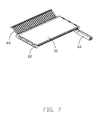
- FIG. 7 is an assembling perspective view of the third terminal block and the shielding plate shown in FIG. 6 ;
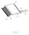
- FIG. 8 is another assembling perspective view shown in FIG. 7 .
- an electrical connector 100 is used for mating with a card edge of a Central Processing Unit.
- the electrical connector 100 includes a plurality of terminal blocks stacked together in a vertical direction, an insulative shell 40 and a shielding shell 50 .
- the insulative shell 40 and the shielding shell 50 cover the terminal blocks.
- the shielding shell 50 is located behind the insulative shell 40 .
- the terminal blocks includes a first terminal block 10 , a second terminal block 11 , a third terminal block 20 and a fourth terminal block 21 .
- the third terminal block 20 is stacked at a lateral side of the first terminal block 10 .
- the fourth terminal block 21 is stacked at a lateral side of the second terminal block 11 .
- the structure of the first terminal block 10 is same as the structure of the second terminal block 11 .
- the structure of the third terminal block 20 is same as the structure of the fourth terminal block 21 .
- the first terminal block 10 includes a first insulative plate 12 and a plurality of first terminals 14 fixed in the first insulative plate 12 .
- the first insulative plate 12 of the first terminal block 10 and the first insulative plate 12 of the second terminal block 11 are shaped as a horizontal plate structure and stacked together in the vertical direction.
- the first terminals 14 are arranged in a horizontal direction perpendicular to the vertical direction.
- the first terminal 14 extends along a third direction perpendicular to the vertical direction and the horizontal direction.
- the first terminal 14 includes a first deflectable contacting arm 15 and a first connecting foot 16 .
- the first deflectable contacting arm 15 of the first terminal block 10 and the first deflectable contacting arm 15 of the second terminal block 11 bend face to face and form an inserting space in the vertical direction.
- the third terminal block 20 includes a second insulative plate 22 and a plurality of second terminals 24 fixed in the second insulative plate 22 .
- the second insulative plate 22 of the third terminal block 20 and the second insulative plate 22 of the fourth terminal block 21 are shaped as a horizontal plate structure.
- the second insulative plate 22 of the third terminal block 20 is stacked at a lateral side of the first insulative plate 12 of the first terminal block 10 in the vertical direction.
- the second insulative plate 22 of the fourth terminal block 21 is stacked at a lateral side of the first insulative plate 12 of the second terminal block 21 in the vertical direction.
- the second terminals 24 are arranged in the horizontal direction perpendicular to the vertical direction.
- the second terminal 24 extends along the third direction perpendicular to the vertical direction and the horizontal direction.
- the second terminal 24 includes a second deflectable contacting arm 25 and a second connecting foot 26 .
- the second deflectable contacting arm 25 of the third terminal block 20 and the second deflectable contacting arm 25 of the fourth terminal block 21 bend face to face and form an inserting space in the vertical direction.
- the second deflectable contacting arm 25 of the third terminal block 20 and the second deflectable contacting arm 25 of the fourth terminal block 21 are located in front of the first deflectable contacting arm 15 of the first terminal block 10 and the first deflectable contacting arm 15 of the second terminal block 11 .
- the first deflectable arms 15 of the first and second terminal blocks 10 , 11 and the second deflectable arms 25 of the third and fourth terminal blocks 20 , 21 extend beyond the first and second insulative plate 12 , 22 .
- the electrical connector 100 also includes a shielding plate 30 disposed between the first insulative plate 12 of the first terminal block 10 and the second insulative plate 22 of the third terminal block 20 .
- the electrical connector 100 also includes another shielding plate 30 disposed between the first insulative plate 12 of the second terminal block 11 and the second insulative plate 22 of the fourth terminal block 21 . Referring to FIGS. 6-7 , each lateral side of the second insulative plate 22 of the third terminal block 20 defines three latching slots 221 .
- Each lateral side of the second insulative plate 22 of the fourth terminal block 21 defines three latching slots 221 .
- Each lateral side of the shielding plate 30 includes three latching arms 31 .
- the latching arms 31 cooperate with the latching slots 221 , respectively.
- the shielding plate 30 is fixed to the second insulative plate 22 .
- the vertical direction is defined as a first direction
- the horizontal direction is defined as a second direction.
- the insulative shell 40 defines an opening.
- the insulative shell 40 covers the first insulative plate 12 and the second insulative plate 22 .
- the insulative shell 40 surrounds the first deflectable contacting arms 15 .
- the first deflectable contacting arm 15 is located behind the opening.
- the shielding shell 50 covers the first insulative plate 12 and the second insulative plate 22 .
- the shielding shell 50 is located behind the insulative shell 40 .
- Each lateral side of the second insulative plate 22 of the fourth terminal block 21 includes a plurality of protrusions 220 .
- the shielding shell 50 includes three lateral walls 51 .
- the shielding shell 50 also includes a plurality of fixing holes 52 for fixing to the protrusions 220 , respectively.
- Each first insulative plate 12 defines a first slot 13 and each second insulative plate 22 defines a second slot 23 .
- the first connecting foot 16 of the first terminal 14 is received in the first slot 13
- the second connecting foot 26 of the second terminal 24 is received in the second slot 23 .
- the connecting foot of the terminal is soldered to a cable.
- the first terminal block, the second terminal block, the third terminal block and the fourth terminal block are stacked together in the first direction.
- a height of the electrical connector can be adjusted by changing the number of terminal blocks. So, the electrical connector can mate with many different kinds of Central Processing Units.
Landscapes
- Connector Housings Or Holding Contact Members (AREA)
- Details Of Connecting Devices For Male And Female Coupling (AREA)
Abstract
Description
Claims (17)
Applications Claiming Priority (3)
| Application Number | Priority Date | Filing Date | Title |
|---|---|---|---|
| CN201520697925.6 | 2015-09-10 | ||
| CN201520697925U | 2015-09-10 | ||
| CN201520697925.6U CN205069933U (en) | 2015-09-10 | 2015-09-10 | Electric connector |
Publications (2)
| Publication Number | Publication Date |
|---|---|
| US20170077632A1 US20170077632A1 (en) | 2017-03-16 |
| US9837740B2 true US9837740B2 (en) | 2017-12-05 |
Family
ID=55396443
Family Applications (1)
| Application Number | Title | Priority Date | Filing Date |
|---|---|---|---|
| US15/262,357 Active US9837740B2 (en) | 2015-09-10 | 2016-09-12 | Electrical connector |
Country Status (3)
| Country | Link |
|---|---|
| US (1) | US9837740B2 (en) |
| CN (1) | CN205069933U (en) |
| TW (1) | TWM544133U (en) |
Cited By (5)
| Publication number | Priority date | Publication date | Assignee | Title |
|---|---|---|---|---|
| US10855020B1 (en) * | 2019-09-17 | 2020-12-01 | Te Connectivity Corporation | Card edge connector having a contact positioner |
| TWI792514B (en) * | 2020-10-19 | 2023-02-11 | 大陸商立訊精密工業股份有限公司 | Electric connector |
| US11799235B2 (en) | 2021-04-06 | 2023-10-24 | Foxconn (Kunshan) Computer Connector Co., Ltd. | Electrical connector |
| US11817654B2 (en) | 2020-07-18 | 2023-11-14 | Foxconn (Kunshan) Computer Connector Co., Ltd. | Electrical device |
| US12401150B2 (en) | 2022-04-15 | 2025-08-26 | Foxconn (Kunshan) Computer Connector Co., Ltd. | Electrical connector having four terminal modules and a pair of metallic side plates fixing the four terminal modules |
Families Citing this family (16)
| Publication number | Priority date | Publication date | Assignee | Title |
|---|---|---|---|---|
| CN107994402B (en) * | 2016-10-26 | 2021-02-26 | 富士康(昆山)电脑接插件有限公司 | Socket connector |
| TWI631776B (en) * | 2017-09-07 | 2018-08-01 | 至良科技股份有限公司 | Terminal module and its electrical connector |
| TWI631779B (en) * | 2017-09-07 | 2018-08-01 | 至良科技股份有限公司 | Terminal module and its electrical connector |
| CN109510017B (en) * | 2017-09-14 | 2020-06-12 | 至良科技股份有限公司 | Terminal module and its electrical connector |
| CN109546393B (en) * | 2017-09-22 | 2020-07-17 | 至良科技股份有限公司 | Terminal module and its electrical connector |
| TWI640133B (en) * | 2017-09-28 | 2018-11-01 | 至良科技股份有限公司 | Electrical connector |
| CN109659731B (en) * | 2017-10-12 | 2020-11-24 | 至良科技股份有限公司 | electrical connector |
| CN109728453B (en) * | 2017-10-26 | 2021-10-26 | 富士康(昆山)电脑接插件有限公司 | Electrical connector |
| CN109713489A (en) * | 2017-10-26 | 2019-05-03 | 富士康(昆山)电脑接插件有限公司 | Electric connector |
| CN109787000B (en) * | 2017-11-11 | 2021-11-19 | 富士康(昆山)电脑接插件有限公司 | Double-sided socket connector and electrical system thereof |
| CN110021839B (en) * | 2018-01-06 | 2021-11-19 | 富士康(昆山)电脑接插件有限公司 | Socket connector assembly |
| WO2019139882A1 (en) | 2018-01-09 | 2019-07-18 | Molex, Llc | High density receptacle |
| CN108598782B (en) * | 2018-06-01 | 2024-03-26 | 广东拓亿达电子科技有限公司 | SFP-DD high-speed signal electric connector and assembling method thereof |
| JP7259378B2 (en) * | 2019-02-12 | 2023-04-18 | I-Pex株式会社 | electrical connector |
| CN113629423A (en) * | 2020-05-09 | 2021-11-09 | 富士康(昆山)电脑接插件有限公司 | Electrical connector assembly |
| US11322894B2 (en) * | 2020-05-09 | 2022-05-03 | Foxconn (Kunshan) Computer Connector Co., Ltd. | Electrical connector assembly with high speed double density contact arrangement |
Citations (23)
| Publication number | Priority date | Publication date | Assignee | Title |
|---|---|---|---|---|
| US5425651A (en) * | 1994-03-04 | 1995-06-20 | The Whitaker Corporation | Card edge connector providing non-simultaneous electrical connections |
| TWM267697U (en) | 2003-07-01 | 2005-06-11 | Hon Hai Prec Ind Co Ltd | Cable assembly with internal circuit modules |
| US7585188B2 (en) * | 2004-07-07 | 2009-09-08 | Molex Incorporated | Edge card connector assembly with high-speed terminals |
| US7625243B2 (en) * | 2007-06-13 | 2009-12-01 | Hon Hai Precision Ind. Co., Ltd. | Extension to version 2.0 universal serial bus connector with improved contact arrangement |
| US7651379B1 (en) * | 2008-10-23 | 2010-01-26 | Hon Hai Precision Ind. Co., Ltd | Cable assembly with improved termination disposition |
| US7785140B2 (en) * | 2008-09-16 | 2010-08-31 | Tyco Electronics Corporation | Modular electrical connector with opposing contact support members |
| TWM393890U (en) | 2010-05-18 | 2010-12-01 | Hon Hai Prec Ind Co Ltd | Cable connector assembly |
| US20110003514A1 (en) * | 2004-02-12 | 2011-01-06 | Super Talent Electronics, Inc. | Dual-personality extended usb plugs and receptacles using with pcba and cable assembly |
| US20110070779A1 (en) * | 2009-03-11 | 2011-03-24 | Hon Hai Precision Industry Co., Ltd. | Electrical connector having contact arrangement ensuring reliable high speed transmission |
| US20110249948A1 (en) * | 2010-04-07 | 2011-10-13 | Hon Hai Precision Industry Co., Ltd. | Cable assembly with elecrical and optical transmitting |
| US8152568B2 (en) * | 2009-09-15 | 2012-04-10 | Hon Hai Precision Ind. Co., Ltd. | Cable assembly with new interface |
| US20120315796A1 (en) * | 2011-06-10 | 2012-12-13 | Tze Yeong Pang | Cross Talk Reduction For A High Speed Electrical Connector |
| US20130005164A1 (en) * | 2011-06-29 | 2013-01-03 | Tyco Electronics Nederland Bv | Electrical connector |
| US20130196550A1 (en) * | 2010-02-15 | 2013-08-01 | Molex Incorporated | Differentially coupled connector |
| US20130309906A1 (en) * | 2010-12-13 | 2013-11-21 | Fci | High Speed Edge Card Connector |
| US8740643B2 (en) * | 2011-08-02 | 2014-06-03 | Hon Hai Precision Industry Co., Ltd. | Electrical receptacle connector compatible with existing electrical plug and complementary plug |
| US20140302719A1 (en) * | 2012-10-09 | 2014-10-09 | Molex Incorlporated | Card edge connector |
| US8858237B2 (en) * | 2011-06-16 | 2014-10-14 | Hon Hai Precision Industry Co., Ltd. | Receptacle connector having improved contact modules |
| US8956167B2 (en) * | 2011-11-23 | 2015-02-17 | Hon Hai Precision Industry Co., Ltd. | Cable end connector with connecting bar |
| US9306345B2 (en) * | 2014-02-17 | 2016-04-05 | Speed Tech Corp. | High-density cable end connector |
| US9437982B2 (en) * | 2013-08-12 | 2016-09-06 | Hon Hai Precision Industry Co., Ltd. | Cable connector assembly |
| US9472905B2 (en) * | 2014-12-30 | 2016-10-18 | Shenzhen Deren Electronic Co., Ltd | Electric connector and cable connector assembly |
| US9478884B2 (en) * | 2013-11-20 | 2016-10-25 | Foxconn Interconnect Technology Limited | Electrical connector having an insulative plate with a slot |
-
2015
- 2015-09-10 CN CN201520697925.6U patent/CN205069933U/en not_active Expired - Lifetime
- 2015-10-08 TW TW104216149U patent/TWM544133U/en not_active IP Right Cessation
-
2016
- 2016-09-12 US US15/262,357 patent/US9837740B2/en active Active
Patent Citations (23)
| Publication number | Priority date | Publication date | Assignee | Title |
|---|---|---|---|---|
| US5425651A (en) * | 1994-03-04 | 1995-06-20 | The Whitaker Corporation | Card edge connector providing non-simultaneous electrical connections |
| TWM267697U (en) | 2003-07-01 | 2005-06-11 | Hon Hai Prec Ind Co Ltd | Cable assembly with internal circuit modules |
| US20110003514A1 (en) * | 2004-02-12 | 2011-01-06 | Super Talent Electronics, Inc. | Dual-personality extended usb plugs and receptacles using with pcba and cable assembly |
| US7585188B2 (en) * | 2004-07-07 | 2009-09-08 | Molex Incorporated | Edge card connector assembly with high-speed terminals |
| US7625243B2 (en) * | 2007-06-13 | 2009-12-01 | Hon Hai Precision Ind. Co., Ltd. | Extension to version 2.0 universal serial bus connector with improved contact arrangement |
| US7785140B2 (en) * | 2008-09-16 | 2010-08-31 | Tyco Electronics Corporation | Modular electrical connector with opposing contact support members |
| US7651379B1 (en) * | 2008-10-23 | 2010-01-26 | Hon Hai Precision Ind. Co., Ltd | Cable assembly with improved termination disposition |
| US20110070779A1 (en) * | 2009-03-11 | 2011-03-24 | Hon Hai Precision Industry Co., Ltd. | Electrical connector having contact arrangement ensuring reliable high speed transmission |
| US8152568B2 (en) * | 2009-09-15 | 2012-04-10 | Hon Hai Precision Ind. Co., Ltd. | Cable assembly with new interface |
| US20130196550A1 (en) * | 2010-02-15 | 2013-08-01 | Molex Incorporated | Differentially coupled connector |
| US20110249948A1 (en) * | 2010-04-07 | 2011-10-13 | Hon Hai Precision Industry Co., Ltd. | Cable assembly with elecrical and optical transmitting |
| TWM393890U (en) | 2010-05-18 | 2010-12-01 | Hon Hai Prec Ind Co Ltd | Cable connector assembly |
| US20130309906A1 (en) * | 2010-12-13 | 2013-11-21 | Fci | High Speed Edge Card Connector |
| US20120315796A1 (en) * | 2011-06-10 | 2012-12-13 | Tze Yeong Pang | Cross Talk Reduction For A High Speed Electrical Connector |
| US8858237B2 (en) * | 2011-06-16 | 2014-10-14 | Hon Hai Precision Industry Co., Ltd. | Receptacle connector having improved contact modules |
| US20130005164A1 (en) * | 2011-06-29 | 2013-01-03 | Tyco Electronics Nederland Bv | Electrical connector |
| US8740643B2 (en) * | 2011-08-02 | 2014-06-03 | Hon Hai Precision Industry Co., Ltd. | Electrical receptacle connector compatible with existing electrical plug and complementary plug |
| US8956167B2 (en) * | 2011-11-23 | 2015-02-17 | Hon Hai Precision Industry Co., Ltd. | Cable end connector with connecting bar |
| US20140302719A1 (en) * | 2012-10-09 | 2014-10-09 | Molex Incorlporated | Card edge connector |
| US9437982B2 (en) * | 2013-08-12 | 2016-09-06 | Hon Hai Precision Industry Co., Ltd. | Cable connector assembly |
| US9478884B2 (en) * | 2013-11-20 | 2016-10-25 | Foxconn Interconnect Technology Limited | Electrical connector having an insulative plate with a slot |
| US9306345B2 (en) * | 2014-02-17 | 2016-04-05 | Speed Tech Corp. | High-density cable end connector |
| US9472905B2 (en) * | 2014-12-30 | 2016-10-18 | Shenzhen Deren Electronic Co., Ltd | Electric connector and cable connector assembly |
Cited By (6)
| Publication number | Priority date | Publication date | Assignee | Title |
|---|---|---|---|---|
| US10855020B1 (en) * | 2019-09-17 | 2020-12-01 | Te Connectivity Corporation | Card edge connector having a contact positioner |
| US11817654B2 (en) | 2020-07-18 | 2023-11-14 | Foxconn (Kunshan) Computer Connector Co., Ltd. | Electrical device |
| TWI792514B (en) * | 2020-10-19 | 2023-02-11 | 大陸商立訊精密工業股份有限公司 | Electric connector |
| US11658441B2 (en) | 2020-10-19 | 2023-05-23 | Luxshare Precision Industry Co., Ltd. | Cable connector with improved shielding performance |
| US11799235B2 (en) | 2021-04-06 | 2023-10-24 | Foxconn (Kunshan) Computer Connector Co., Ltd. | Electrical connector |
| US12401150B2 (en) | 2022-04-15 | 2025-08-26 | Foxconn (Kunshan) Computer Connector Co., Ltd. | Electrical connector having four terminal modules and a pair of metallic side plates fixing the four terminal modules |
Also Published As
| Publication number | Publication date |
|---|---|
| CN205069933U (en) | 2016-03-02 |
| US20170077632A1 (en) | 2017-03-16 |
| TWM544133U (en) | 2017-06-21 |
Similar Documents
| Publication | Publication Date | Title |
|---|---|---|
| US9837740B2 (en) | Electrical connector | |
| US11605920B2 (en) | Backplane connector with improved shielding effect | |
| USRE49901E1 (en) | Electrical receptacle for transmitting high speed signal | |
| US10096947B2 (en) | Electrical connector and electrical device assembled with the same therein | |
| US9728866B2 (en) | Electrical connector | |
| US9793633B2 (en) | Electrical connector with a grounding bar connecting the terminals of a plurality of ground contact wafers and shielding braids of cables | |
| US9450355B2 (en) | USB plug connector and method for manufacturing the same | |
| US9653849B2 (en) | Electrical connector having good anti-EMI perfprmance | |
| US9627826B2 (en) | Power connector assembly with contacts conveniently soldered to cable wires | |
| US10109937B2 (en) | Electrical cable connector | |
| US9722360B2 (en) | Electrical connector having improved terminals | |
| US20160141805A1 (en) | Receptacle connector having improved insulative housing | |
| US20160118750A1 (en) | Electrical connector having power terminals | |
| US20140349514A1 (en) | Electrical connector with heat-dissipation feauter thereof | |
| US9806468B2 (en) | Cable connector with wafer structure thereof | |
| US10381776B2 (en) | Connector assembly with an improved latch member having a shorter length | |
| US20160126677A1 (en) | Electrical connector | |
| US9509099B2 (en) | Electrical connector having improved anti-EMI performance | |
| US10236610B2 (en) | Grounding bar contacting shielding plate, grounding contact, wire braiding and shell | |
| US20160329662A1 (en) | Electrical connector and electrical connector assembly thereof | |
| US10148043B2 (en) | Electrical connector with extended grounding contact touching shell | |
| US20080293292A1 (en) | Cable connector assembly with wire management member thereof | |
| US20100297878A1 (en) | Cable connector having improved gounding means | |
| US8678853B2 (en) | Cable connector assembly with reliable connection | |
| US20150244098A1 (en) | Electrical connector having improved insulative housing |
Legal Events
| Date | Code | Title | Description |
|---|---|---|---|
| AS | Assignment |
Owner name: FOXCONN INTERCONNECT TECHNOLOGY LIMITED, CAYMAN IS Free format text: ASSIGNMENT OF ASSIGNORS INTEREST;ASSIGNOR:LIAO, FANG-JWU;REEL/FRAME:039701/0201 Effective date: 20160908 |
|
| STCF | Information on status: patent grant |
Free format text: PATENTED CASE |
|
| MAFP | Maintenance fee payment |
Free format text: PAYMENT OF MAINTENANCE FEE, 4TH YEAR, LARGE ENTITY (ORIGINAL EVENT CODE: M1551); ENTITY STATUS OF PATENT OWNER: LARGE ENTITY Year of fee payment: 4 |
|
| MAFP | Maintenance fee payment |
Free format text: PAYMENT OF MAINTENANCE FEE, 8TH YEAR, LARGE ENTITY (ORIGINAL EVENT CODE: M1552); ENTITY STATUS OF PATENT OWNER: LARGE ENTITY Year of fee payment: 8 |