US9837709B2 - Broadband helical antenna with cutoff pattern - Google Patents
Broadband helical antenna with cutoff pattern Download PDFInfo
- Publication number
- US9837709B2 US9837709B2 US14/890,610 US201514890610A US9837709B2 US 9837709 B2 US9837709 B2 US 9837709B2 US 201514890610 A US201514890610 A US 201514890610A US 9837709 B2 US9837709 B2 US 9837709B2
- Authority
- US
- United States
- Prior art keywords
- antenna
- cylinder
- conductors
- spiral
- winding angle
- Prior art date
- Legal status (The legal status is an assumption and is not a legal conclusion. Google has not performed a legal analysis and makes no representation as to the accuracy of the status listed.)
- Active, expires
Links
- 239000004020 conductor Substances 0.000 claims abstract description 38
- 238000004804 winding Methods 0.000 claims abstract description 20
- 230000005284 excitation Effects 0.000 claims abstract description 16
- 230000006978 adaptation Effects 0.000 description 1
- 238000000034 method Methods 0.000 description 1
- 238000012986 modification Methods 0.000 description 1
- 230000004048 modification Effects 0.000 description 1
- 230000010287 polarization Effects 0.000 description 1
- 239000000758 substrate Substances 0.000 description 1
Images


Classifications
-
- H—ELECTRICITY
- H01—ELECTRIC ELEMENTS
- H01Q—ANTENNAS, i.e. RADIO AERIALS
- H01Q1/00—Details of, or arrangements associated with, antennas
- H01Q1/36—Structural form of radiating elements, e.g. cone, spiral, umbrella; Particular materials used therewith
-
- H—ELECTRICITY
- H01—ELECTRIC ELEMENTS
- H01Q—ANTENNAS, i.e. RADIO AERIALS
- H01Q11/00—Electrically-long antennas having dimensions more than twice the shortest operating wavelength and consisting of conductive active radiating elements
- H01Q11/02—Non-resonant antennas, e.g. travelling-wave antenna
- H01Q11/08—Helical antennas
-
- H—ELECTRICITY
- H01—ELECTRIC ELEMENTS
- H01Q—ANTENNAS, i.e. RADIO AERIALS
- H01Q21/00—Antenna arrays or systems
- H01Q21/24—Combinations of antenna units polarised in different directions for transmitting or receiving circularly and elliptically polarised waves or waves linearly polarised in any direction
-
- H—ELECTRICITY
- H01—ELECTRIC ELEMENTS
- H01Q—ANTENNAS, i.e. RADIO AERIALS
- H01Q25/00—Antennas or antenna systems providing at least two radiating patterns
- H01Q25/001—Crossed polarisation dual antennas
-
- H—ELECTRICITY
- H01—ELECTRIC ELEMENTS
- H01Q—ANTENNAS, i.e. RADIO AERIALS
- H01Q9/00—Electrically-short antennas having dimensions not more than twice the operating wavelength and consisting of conductive active radiating elements
- H01Q9/04—Resonant antennas
- H01Q9/06—Details
- H01Q9/10—Junction boxes specially adapted for supporting adjacent ends of divergent elements
- H01Q9/12—Junction boxes specially adapted for supporting adjacent ends of divergent elements adapted for adjustment of angle between elements
-
- H—ELECTRICITY
- H01—ELECTRIC ELEMENTS
- H01Q—ANTENNAS, i.e. RADIO AERIALS
- H01Q9/00—Electrically-short antennas having dimensions not more than twice the operating wavelength and consisting of conductive active radiating elements
- H01Q9/04—Resonant antennas
- H01Q9/16—Resonant antennas with feed intermediate between the extremities of the antenna, e.g. centre-fed dipole
- H01Q9/26—Resonant antennas with feed intermediate between the extremities of the antenna, e.g. centre-fed dipole with folded element or elements, the folded parts being spaced apart a small fraction of operating wavelength
- H01Q9/27—Spiral antennas
Definitions
- GNSS Global navigation satellite systems
- GPS Global Positioning System
- GLONASS Russian global navigation system
- a GNSS antenna has to provide signal reception in the whole GNSS range, namely, a low-frequency band 1164-1300 MHz and high-frequency band 1525-1610 MHz.
- the value of the multipath error is proportional to the ratio
- This ratio is normally called the Down/Up ratio.
- ⁇ is the elevation angle over the horizon
- a spatial region where ⁇ >0 is the upper or front hemisphere, otherwise, a spatial region at ⁇ 0 is called the lower or backward hemisphere.
- the value F( ⁇ ) in the upper hemisphere is not to highly vary.
- Receiving antennas thus need to provide such an AP whose level is negligibly varied in the upper hemisphere, sharply drops in crossing the direction to the local horizon, and is small in the lower hemisphere. Also, such an antenna pattern needs to be provided over whole operational frequency range.
- the objective of the invention is an antenna with an antenna pattern whose level varies slightly in the upper hemisphere, drops in the direction of the local horizon, and is small in the lower hemisphere, over the entire desired frequency range.
- a circularly-polarized antenna is utilized in the backfire operation mode, the antenna comprising a set of elements each representing a quadruple cylindrical spiral.
- the spiral winding angle for neighboring elements is different.
- An excitation circuit is arranged above the antenna.
- an antenna for receiving circularly polarized signals includes a hollow dielectric cylinder (used as mechanical support for the conductors) oriented along a vertical axis; four spiral conducting elements wrapped around the cylinder; the four spiral conducting elements are divided into a plurality of longitudinal sections.
- the conducting elements in each section have a constant winding angle around the cylinder.
- the winding angle of all of the conducting elements in the same longitudinal section is the same.
- Neighboring longitudinal sections have different winding angles relative to each other.
- An excitation circuit is connected to the conducting elements.
- FIG. 1 shows an appearance of a quadruple cylindrical spiral antenna
- FIGS. 2A, 2B show quadruple cylindrical spiral elements
- FIGS. 3A, 3B, 3C present embodiments of the design of a quadruple cylindrical spiral antenna
- FIG. 4 shows parameters for design embodiments of a quadruple cylindrical spiral antenna shown in FIG. 3A, 3B, 3C ;
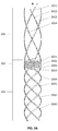
- FIGS. 5A, 5B show one of embodiments for a quadruple cylindrical spiral antenna
- FIG. 6A depicts graphs of the antenna pattern for the design shown in FIG. 3A ;
- FIG. 6B presents graphs of the antenna pattern for the design shown in FIG. 3B ;
- FIG. 6C shows graphs of the antenna pattern for the design shown in FIG. 3C ;
- a wideband circularly-polarized antenna is proposed to receive GNSS signals.
- the antenna comprises a set of quadruple spiral elements 101 , an excitation circuit 102 , and a power cable 103 .
- the excitation circuit 102 is located above, and, thereby, the backfire operation mode is implemented.
- the power cable 103 is in the center of the antenna.
- the upper end of the power cable 103 is connected to the excitation circuit 102 .
- the lower end of the power cable 103 is connected to the input of a low-noise amplifier (the LNA is not shown).
- the excitation circuit is well-known and is an equal-amplitude power splitter with one input and four outputs. The phase difference between neighboring outputs is 90 degrees.
- Each output of the excitation circuit is connected to a corresponding conductor of the first (upper) quadruple spiral element, thereby providing excitation of a right hand circular polarization (RHCP) wave in the positive direction of the vertical antenna axis z.
- the antenna pattern has maximum in this direction.
- Each of quadruple spiral elements consists of four conductors wound at the same angle and forming a quadruple spiral whose axis is aligned with the z axis. Each conductor is one spiral turn of the quadruple spiral. The winding angle for the conductors is the same for the entire quadruple spiral element.
- FIG. 2A shows quadruple spiral elements 201 , 202 , 203 , 204 and corresponding forming conductors: 2011 , 2012 , 2013 , 2014 ; 2021 , 2022 , 2023 , 2024 , 2031 , 2032 , 2033 , 2034 .
- the conductors are applied to a dielectric substrate (not shown) that is further bent to form a hollow cylinder.
- Each conductor has a first (top) and second (bottom) ends. From FIG. 2B , the first and second conductor ends (for example, 2024 and 2034 ) of neighboring spiral elements (for example, 202 and 203 ) geometrically match.
- the antenna includes a set of two or more quadruple spiral elements.
- a feature of the design is the same winding angle for the conductors of the same spiral elements, while the conductors of the neighboring spiral elements have different winding angles.
- FIGS. 3A, 3B, 3C show possible embodiments of the spiral antenna.
- FIG. 3A presents a design of the spiral antenna with seven spiral elements
- FIG. 3B shows a design with nine spiral elements
- the embodiment of FIG. 3C includes eleven spiral elements.
- Table of FIG. 4 there are parameters of the embodiments shown. Note that although the described embodiments use 4 spiral conductors, more (e.g., 6 or 8) or fewer (e.g., 3) can also be used.
- First and second conductor ends of the neighboring spiral elements can mismatch.
- FIG. 5A, 5B show an embodiment with mismatching first and second conductor ends of the neighboring elements.
- the conductors of the neighboring spiral elements are connected to each other by conductors 51 , 52 , 53 , 54 which are circle segments.
Landscapes
- Variable-Direction Aerials And Aerial Arrays (AREA)
Abstract
Description
for different embodiments. Embodiments 2 and 3 are seen to provide a DU (θ=10°) ratio at least −15 dB in the whole frequency range from 1164-1610 MHz. Embodiment 1 produces the worst ratio DU (θ=10°) in the high-frequency part of the range, but the actual antenna has the smallest dimensions, of the three embodiments discussed herein.
Claims (11)
Priority Applications (1)
| Application Number | Priority Date | Filing Date | Title |
|---|---|---|---|
| US15/641,285 US10637137B2 (en) | 2015-04-09 | 2017-07-04 | Broadband helical antenna with cutoff pattern |
Applications Claiming Priority (1)
| Application Number | Priority Date | Filing Date | Title |
|---|---|---|---|
| PCT/RU2015/000234 WO2016163909A1 (en) | 2015-04-09 | 2015-04-09 | Broadband helical antenna with cutoff pattern |
Related Parent Applications (1)
| Application Number | Title | Priority Date | Filing Date |
|---|---|---|---|
| PCT/RU2015/000234 A-371-Of-International WO2016163909A1 (en) | 2015-04-09 | 2015-04-09 | Broadband helical antenna with cutoff pattern |
Related Child Applications (1)
| Application Number | Title | Priority Date | Filing Date |
|---|---|---|---|
| US15/641,285 Continuation-In-Part US10637137B2 (en) | 2015-04-09 | 2017-07-04 | Broadband helical antenna with cutoff pattern |
Publications (2)
| Publication Number | Publication Date |
|---|---|
| US20170187103A1 US20170187103A1 (en) | 2017-06-29 |
| US9837709B2 true US9837709B2 (en) | 2017-12-05 |
Family
ID=57073255
Family Applications (1)
| Application Number | Title | Priority Date | Filing Date |
|---|---|---|---|
| US14/890,610 Active 2035-08-28 US9837709B2 (en) | 2015-04-09 | 2015-04-09 | Broadband helical antenna with cutoff pattern |
Country Status (2)
| Country | Link |
|---|---|
| US (1) | US9837709B2 (en) |
| WO (1) | WO2016163909A1 (en) |
Cited By (1)
| Publication number | Priority date | Publication date | Assignee | Title |
|---|---|---|---|---|
| US20170301984A1 (en) * | 2015-04-09 | 2017-10-19 | Topcon Positioning Systems, Inc. | Broadband helical antenna with cutoff pattern |
Families Citing this family (3)
| Publication number | Priority date | Publication date | Assignee | Title |
|---|---|---|---|---|
| WO2016163909A1 (en) * | 2015-04-09 | 2016-10-13 | Limited Liability Company "Topcon Positioning Systems" | Broadband helical antenna with cutoff pattern |
| WO2020101519A1 (en) * | 2018-11-13 | 2020-05-22 | Limited Liability Company "Topcon Positioning Systems" | Compact integrated gnss-uhf antenna system |
| CN109638424A (en) * | 2018-12-19 | 2019-04-16 | 航天恒星科技有限公司 | A kind of miniaturization Monobrachial spiral antenna |
Citations (19)
| Publication number | Priority date | Publication date | Assignee | Title |
|---|---|---|---|---|
| US4148030A (en) * | 1977-06-13 | 1979-04-03 | Rca Corporation | Helical antennas |
| US4161737A (en) * | 1977-10-03 | 1979-07-17 | Albright Eugene A | Helical antenna |
| US4163981A (en) * | 1978-03-27 | 1979-08-07 | Wilson Thomas J | Spring tunable helical whip antenna |
| US4169267A (en) * | 1978-06-19 | 1979-09-25 | The United States Of America As Represented By The Secretary Of The Air Force | Broadband helical antennas |
| US6172655B1 (en) * | 1999-02-12 | 2001-01-09 | Lockheed Martin Corporation | Ultra-short helical antenna and array thereof |
| US6229498B1 (en) * | 1998-10-09 | 2001-05-08 | Matsushita Electric Industrial Co., Ltd. | Helical antenna |
| US6246379B1 (en) * | 1999-07-19 | 2001-06-12 | The United States Of America As Represented By The Secretary Of The Navy | Helix antenna |
| US6288686B1 (en) * | 2000-06-23 | 2001-09-11 | The United States Of America As Represented By The Secretary Of The Navy | Tapered direct fed quadrifilar helix antenna |
| US6300917B1 (en) * | 1999-05-27 | 2001-10-09 | Sarantel Limited | Antenna |
| US6344834B1 (en) | 2000-04-20 | 2002-02-05 | The United States Of America As Represented By The Secretary Of The Navy | Low angle, high angle quadrifilar helix antenna |
| US6407720B1 (en) * | 1999-07-19 | 2002-06-18 | The United States Of America As Represented By The Secretary Of The Navy | Capacitively loaded quadrifilar helix antenna |
| US20030016184A1 (en) * | 2001-07-17 | 2003-01-23 | Kitching David R. | Resonant length multi-element helical antenna |
| US6587081B2 (en) * | 2000-05-18 | 2003-07-01 | Mitsumi Electric Co., Ltd. | Helical antenna, antenna unit, composite antenna |
| RU2208272C2 (en) | 1996-07-31 | 2003-07-10 | Квэлкомм Инкорпорейтед | Helix antenna with bent segments |
| US6836257B2 (en) * | 2000-09-15 | 2004-12-28 | France Telecom | Variable-pitch helical antenna, and corresponding method |
| US7015873B1 (en) * | 2004-06-10 | 2006-03-21 | Lockheed Martin Corporation | Thermally dissipating high RF power radiating antenna system |
| EP1833116A2 (en) | 2004-05-26 | 2007-09-12 | Delphi Technologies, Inc. | Quadrifilar helical antenna |
| RU2395877C1 (en) | 2009-07-22 | 2010-07-27 | Открытое акционерное общество "Московское конструкторское бюро "Компас" | Quadrifilar antenna |
| US20170187103A1 (en) * | 2015-04-09 | 2017-06-29 | Limited Liability Company "Topcon Positioning Systems" | Broadband helical antenna with cutoff pattern |
-
2015
- 2015-04-09 WO PCT/RU2015/000234 patent/WO2016163909A1/en not_active Ceased
- 2015-04-09 US US14/890,610 patent/US9837709B2/en active Active
Patent Citations (19)
| Publication number | Priority date | Publication date | Assignee | Title |
|---|---|---|---|---|
| US4148030A (en) * | 1977-06-13 | 1979-04-03 | Rca Corporation | Helical antennas |
| US4161737A (en) * | 1977-10-03 | 1979-07-17 | Albright Eugene A | Helical antenna |
| US4163981A (en) * | 1978-03-27 | 1979-08-07 | Wilson Thomas J | Spring tunable helical whip antenna |
| US4169267A (en) * | 1978-06-19 | 1979-09-25 | The United States Of America As Represented By The Secretary Of The Air Force | Broadband helical antennas |
| RU2208272C2 (en) | 1996-07-31 | 2003-07-10 | Квэлкомм Инкорпорейтед | Helix antenna with bent segments |
| US6229498B1 (en) * | 1998-10-09 | 2001-05-08 | Matsushita Electric Industrial Co., Ltd. | Helical antenna |
| US6172655B1 (en) * | 1999-02-12 | 2001-01-09 | Lockheed Martin Corporation | Ultra-short helical antenna and array thereof |
| US6300917B1 (en) * | 1999-05-27 | 2001-10-09 | Sarantel Limited | Antenna |
| US6407720B1 (en) * | 1999-07-19 | 2002-06-18 | The United States Of America As Represented By The Secretary Of The Navy | Capacitively loaded quadrifilar helix antenna |
| US6246379B1 (en) * | 1999-07-19 | 2001-06-12 | The United States Of America As Represented By The Secretary Of The Navy | Helix antenna |
| US6344834B1 (en) | 2000-04-20 | 2002-02-05 | The United States Of America As Represented By The Secretary Of The Navy | Low angle, high angle quadrifilar helix antenna |
| US6587081B2 (en) * | 2000-05-18 | 2003-07-01 | Mitsumi Electric Co., Ltd. | Helical antenna, antenna unit, composite antenna |
| US6288686B1 (en) * | 2000-06-23 | 2001-09-11 | The United States Of America As Represented By The Secretary Of The Navy | Tapered direct fed quadrifilar helix antenna |
| US6836257B2 (en) * | 2000-09-15 | 2004-12-28 | France Telecom | Variable-pitch helical antenna, and corresponding method |
| US20030016184A1 (en) * | 2001-07-17 | 2003-01-23 | Kitching David R. | Resonant length multi-element helical antenna |
| EP1833116A2 (en) | 2004-05-26 | 2007-09-12 | Delphi Technologies, Inc. | Quadrifilar helical antenna |
| US7015873B1 (en) * | 2004-06-10 | 2006-03-21 | Lockheed Martin Corporation | Thermally dissipating high RF power radiating antenna system |
| RU2395877C1 (en) | 2009-07-22 | 2010-07-27 | Открытое акционерное общество "Московское конструкторское бюро "Компас" | Quadrifilar antenna |
| US20170187103A1 (en) * | 2015-04-09 | 2017-06-29 | Limited Liability Company "Topcon Positioning Systems" | Broadband helical antenna with cutoff pattern |
Non-Patent Citations (2)
| Title |
|---|
| Bankov, Sergei et al., Raschet kvadrifilyarnoi atenny. Sovremennaya elekmtronika, No. 1, 2008. |
| Search Report in PCT/RU2015/000234, dated Feb. 4, 2016. |
Cited By (2)
| Publication number | Priority date | Publication date | Assignee | Title |
|---|---|---|---|---|
| US20170301984A1 (en) * | 2015-04-09 | 2017-10-19 | Topcon Positioning Systems, Inc. | Broadband helical antenna with cutoff pattern |
| US10637137B2 (en) * | 2015-04-09 | 2020-04-28 | Topcon Positioning Systems, Inc. | Broadband helical antenna with cutoff pattern |
Also Published As
| Publication number | Publication date |
|---|---|
| US20170187103A1 (en) | 2017-06-29 |
| WO2016163909A1 (en) | 2016-10-13 |
Similar Documents
| Publication | Publication Date | Title |
|---|---|---|
| US10424836B2 (en) | Horizon nulling helix antenna | |
| US10483631B2 (en) | Decoupled concentric helix antenna | |
| US9520651B2 (en) | Global navigation satellite system antenna with a hollow core | |
| US8648766B2 (en) | Dual circularly polarized antenna | |
| US9960494B2 (en) | Impedance helical antenna forming Π-shaped directional diagram | |
| US8624792B2 (en) | Antenna device for transmitting and receiving electromegnetic signals | |
| CN101533956B (en) | Multi-mode satellite positioning navigation terminal antenna | |
| CN110247169B (en) | A dual-frequency quadruple helix antenna with wide beam characteristics | |
| US9837709B2 (en) | Broadband helical antenna with cutoff pattern | |
| US10381734B2 (en) | Patch antenna with wire radiation elements for high-precision GNSS applications | |
| CN113169456A (en) | Broadband GNSS Antenna System | |
| CA3127203C (en) | Parasitic elements for antenna systems | |
| US10637137B2 (en) | Broadband helical antenna with cutoff pattern | |
| CN112134004B (en) | A Wide-beam Quadruple Helix Antenna with Equal-flux Radiation Characteristics | |
| US9590311B2 (en) | Antenna system with reduced multipath reception | |
| CN111934088B (en) | Planar Broadband Antenna Device | |
| Boccia et al. | A high performance dual frequency microstrip antenna for Global Positioning System | |
| WO2022257203A1 (en) | Broadband helical antenna | |
| Lele et al. | Circularly Periodic Progressive Multi-Band High Impedance Surface Integrated with a Wideband Spiral Antenna for GNSS Applications | |
| Lin et al. | A quadrifilar helix antenna for LEO satellite navigation augmentation module | |
| US11437728B1 (en) | Multi-band quadrifilar helix slot antenna | |
| CN205335420U (en) | Antenna device | |
| CN119209009A (en) | A high-precision satellite signal antenna | |
| Kumar et al. | Open Ended Quadrifilar Helix Suitable for GPS Reception | |
| WO2019221626A1 (en) | Compact integrated gnss antenna system |
Legal Events
| Date | Code | Title | Description |
|---|---|---|---|
| AS | Assignment |
Owner name: TOPCON POSITIONING SYSTEMS, INC., CALIFORNIA Free format text: ASSIGNMENT OF ASSIGNORS INTEREST;ASSIGNORS:STEPANENKO, ANTON PAVLOVICH;ASTAKHOV, ANDREY VITALIEVICH;TATARNIKOV, DMITRY VITALIEVICH;AND OTHERS;REEL/FRAME:037020/0587 Effective date: 20151105 |
|
| STCF | Information on status: patent grant |
Free format text: PATENTED CASE |
|
| MAFP | Maintenance fee payment |
Free format text: PAYMENT OF MAINTENANCE FEE, 4TH YEAR, LARGE ENTITY (ORIGINAL EVENT CODE: M1551); ENTITY STATUS OF PATENT OWNER: LARGE ENTITY Year of fee payment: 4 |
|
| MAFP | Maintenance fee payment |
Free format text: PAYMENT OF MAINTENANCE FEE, 8TH YEAR, LARGE ENTITY (ORIGINAL EVENT CODE: M1552); ENTITY STATUS OF PATENT OWNER: LARGE ENTITY Year of fee payment: 8 |