US983755A - Decorticating-machine. - Google Patents
Decorticating-machine. Download PDFInfo
- Publication number
- US983755A US983755A US44070908A US1908440709A US983755A US 983755 A US983755 A US 983755A US 44070908 A US44070908 A US 44070908A US 1908440709 A US1908440709 A US 1908440709A US 983755 A US983755 A US 983755A
- Authority
- US
- United States
- Prior art keywords
- leaves
- carrier
- machine
- beaters
- chain
- Prior art date
- Legal status (The legal status is an assumption and is not a legal conclusion. Google has not performed a legal analysis and makes no representation as to the accuracy of the status listed.)
- Expired - Lifetime
Links
- 238000010276 construction Methods 0.000 description 12
- 238000010009 beating Methods 0.000 description 8
- XEEYBQQBJWHFJM-UHFFFAOYSA-N Iron Chemical compound [Fe] XEEYBQQBJWHFJM-UHFFFAOYSA-N 0.000 description 4
- 230000007246 mechanism Effects 0.000 description 4
- 239000000969 carrier Substances 0.000 description 3
- 238000004140 cleaning Methods 0.000 description 2
- 229910052742 iron Inorganic materials 0.000 description 2
- 230000000694 effects Effects 0.000 description 1
- 239000000835 fiber Substances 0.000 description 1
- 239000000463 material Substances 0.000 description 1
- 230000002250 progressing effect Effects 0.000 description 1
- 230000000717 retained effect Effects 0.000 description 1
- 238000005096 rolling process Methods 0.000 description 1
Images

Classifications
-
- D—TEXTILES; PAPER
- D01—NATURAL OR MAN-MADE THREADS OR FIBRES; SPINNING
- D01B—MECHANICAL TREATMENT OF NATURAL FIBROUS OR FILAMENTARY MATERIAL TO OBTAIN FIBRES OF FILAMENTS, e.g. FOR SPINNING
- D01B1/00—Mechanical separation of fibres from plant material, e.g. seeds, leaves, stalks
- D01B1/10—Separating vegetable fibres from stalks or leaves
Definitions
- This invention relates to decorticating machines or machines for cleaning the leaves of fibrous plants so as to place the saine in condition for use.
- the machine in general consists in a pair of beating drums around the periphery of which are mounted a number of beaters.
- a carrier which is adapted to securely hold the leaves in position is provided and carries the leaves successively by each of these beating drums which are positioned on opposite sides of the carrier and arranged so as to operate upon opposite ends of the leaves.
- a suitable feeding device is provided for feeding the leaves to the carrier.
- the beating drums are revolved at a high rate of speed and operate with considerable force upon the leaves. It becomes necessary therefore to provide means for securely holding the leaves in position on the carrier and it is to this portion of the machine that this invention more particularly relates.
- Various forms of carriers and devices for holding the leaves in position thereon have been devised.
- the object of this invention is to overcome these difficulties and provide a carrier construction in which the leaves are securely held in position upon the carrier wheel while passing thel beaters and at the same time any excessive loss of power is prevented. This result is accomplished by providing a movable member of peculiar construction, which will be described more fully hereinafter, between the shoe and the carrier wheel. The leaves are held between this movable member and the carrier wheel while the same are being operated upon by the beaters.
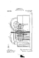
- Figure l is an end elevation of a decorticating machine such as described.
- Fig. 2 is a side elevation of the same.
- Fig. 3 is an enlarged detailed view in section of a portion of the carrier mechanism.
- Beating drums l and 2 are mounted in suitable supports and provided with suitable driving mechanism for rotating the same. Beaters or knives, such as 3 and 4, are mounted upon the periphery of the beating drums l and 2, respectively.
- Carrier wheels 5 and 6 are positioned in front of the beating drums l and 2 and may be driven by means of a beveled gear arrangement from the driving shaft 7. Feeding chains, such as 8, are provided to feed the leaves, which are laid across the same by the operator, to the carrier wheels 5 and 6.
- toothed wheels 9 and 10 Before passing to the first carrier wheel 5 the leaves pass between a set of toothed wheels 9 and 10.
- the object of these toothed wheels is to prevent any large or heavy piece of material, such as a bar of iron, from being carried to the beaters and so causing damage to the machine.
- rlhese toothed wheels 9 and l0 are arranged to yield sufficiently to allow the leaves to pass therethrough, but any unyielding member such as a bar of iron would block the same and cause the machine to stop.
- the operation of the beaters on the leaves in removing the skin and other portions from the inner fibers is well understood and need not be explained here.
- the purpose of providing two sets of beaters for cleaning the opposite ends of the leaves will also be understood.
- the peripheries of the carrier wheels 5 and 6 are circumferentially grooved, as shown in Fig. 3, and at the outer edges the projecting ridges are formed with teeth, as shown in Figs. 2 and 3.
- a movable member or chain which is composed of a number of individual members or links 11, is positioned above a portion of the upper side of each rotating carrier.
- the construction of each of these links is shown in section in Fig. 8.
- the outer surface of each link is formed to correspond with the grooves and teeth in the circumference of the carriers while the opposite surface is smooth.
- Each of these links may be provided with a roller, such as 12, which projects slightly above the smooth inner surface to reduce the friction as the same passes under the pressure shoe, which will shortly be described.
- the provision of the faced bearings 13 provides a means whereby one end of each link is sharply elevated upon the disengagement of said link from said carrier wheel and also insures the engagement of the link with said carrier wheel.
- the faces of the bearings or sprockets 13 are substantially the same length as each link 11, thus insuring the positive engagement of said link by said bearings.
- Fig. 2 the second carrier wheel 6 and its set of links is clearly shown.
- These links 11 form a continuous movable member or chain which Apasses over suitably formed bearings 13 mounted upon the frame of the machine so as to hold the chain in position over the upper portion of the carrier 6.
- a pressure shoe 14 is positioned over the central portion of the chain and is held thereagainst by means of the springs 15.
- the tension of these springs may be adjusted so that the necessary pressure is exerted by the shoe 14, against the chain, which by reason of its construction passes thereunder with very little friction loss and at the same time holds the leaves securely in position on the carrier wheel.
- the movable member or chain is driven continuously by the teeth provided thereon as already described and these teeth also assist in carrying the leaves forward as the carrier wheel is rotated.
- the wheels 5 and G constitute not only feeders or carriers for progressing the leaves past the beaters, but serve as supports normally sustaining the weight of the heavy chain tact upon the chain links, and because of 7 this fact and the rolling character of the main support for the endless chain of links it has been found in practice that the amount of power required to operate this machine is only a small fraction of the amount re- 7 i quired to operate machines of a similar capacity in this art.
- Vhat I claim is:
- a decorticating machine the combination with a plurality of beaters, of mechanisms for feeding' leaves to said beaters, said mechanisms comprising vertical rotating toothed carrier wheels located directly in front of said beaters, feeding chains'coperating with said carrier wheels, a bracket mounted directly over each carrying wheel directly in front of said beaters, supporting arms carried by said brackets, plane-faced sprockets pivotally mounted in said supporting arms, an upwardly curved plate mounted above said supporting arms, an endless chain of links mounted on said plane-faced sprockets and over said upwardly curved plate, each link of said chain being substantially the same length as one face of the sprocket thereby being sharply tilted upon the disengagement of said link l from said wheel, each of said links being provided with teeth adapted to cooperate with the teeth of said carrier wheel, and a shoe operating below said upwardly Curved plate, and against the portion of the chain cooperating with said carrier wheel, springs interposed between said upwardly Curved plate and said shoe, said shoe being retained 1n engagement
Landscapes
- Engineering & Computer Science (AREA)
- Mechanical Engineering (AREA)
- Textile Engineering (AREA)
- Preliminary Treatment Of Fibers (AREA)
Description
G. NORDENHOLT.'
DEGORTIGATING MAGHINE. APPLoATIoN FILED JUNE 27. 190s.
983,755.L Patented Feb.7, 1911.
2 SHEETS-SHEET 1.
@WLMI/@000% my kwam/to@ G. 32,11*@ @Hwang y G. NORDENHOLT.
DEGORTGATING MACHINE.
APPLIOATIQN FILED JUNE 27. 1908.
Patented Feb. 7, 1911.
2 SHEETS-SHEET 2.
@29m/bmw 0 who@ UNIT d GEORGE NORDENI-IOLT,
OF NEW YORK, 1\T. Y.
DECORTICATING-MACHINE.
Specification of Letters Patent.
Patented Feb. 7, 1911.
Application filed .Tune 27, 1908. SerialNo. 440,709.
To all 'whom it may concern:
Be it known that I, GEORGE NoRDnNHoL'r, a citizen of the United States, and resident of the city of New York, in the county of Kings and State of New York, have invented certain new and useful Improvements in Decorticating-lachinea of which the following is a specification.
This invention relates to decorticating machines or machines for cleaning the leaves of fibrous plants so as to place the saine in condition for use.
The general construction of improved machines of this type is well understood and need not be explained in detail herein further than to set out the main features of construction and more specifically the detail features which relate directly to this inven` tion.
The machine in general consists in a pair of beating drums around the periphery of which are mounted a number of beaters. A carrier which is adapted to securely hold the leaves in position is provided and carries the leaves successively by each of these beating drums which are positioned on opposite sides of the carrier and arranged so as to operate upon opposite ends of the leaves. A suitable feeding device is provided for feeding the leaves to the carrier. The beating drums are revolved at a high rate of speed and operate with considerable force upon the leaves. It becomes necessary therefore to provide means for securely holding the leaves in position on the carrier and it is to this portion of the machine that this invention more particularly relates. Various forms of carriers and devices for holding the leaves in position thereon have been devised. Among these the most successful form has been found to be a circular rotating wheel having its circumference provided with alternate ridges and grooves. The leaves upon being fed onto this carrier wheel are held in position while passing the beaters by means of a stationary sho-e. One of the difficulties experienced with this construction was that inexperienced operators would often adjust these shoes so tightly against the carrier wheel that the same would operate as a brake and not only cause a great loss in the power necessary to drive? the machine but leaves of a large size in attempting to pass under the shoe would become jammed and stop the machine.
The object of this invention is to overcome these difficulties and provide a carrier construction in which the leaves are securely held in position upon the carrier wheel while passing thel beaters and at the same time any excessive loss of power is prevented. This result is accomplished by providing a movable member of peculiar construction, which will be described more fully hereinafter, between the shoe and the carrier wheel. The leaves are held between this movable member and the carrier wheel while the same are being operated upon by the beaters.
In the drawings accompanying` this speci- `fication I have shown my invention as applied to a decorticating machine of the type just described.
In the drawings like parts in the several views have been given the same reference numerals.
Figure l is an end elevation of a decorticating machine such as described. Fig. 2 is a side elevation of the same. Fig. 3 is an enlarged detailed view in section of a portion of the carrier mechanism.
Beating drums l and 2 are mounted in suitable supports and provided with suitable driving mechanism for rotating the same. Beaters or knives, such as 3 and 4, are mounted upon the periphery of the beating drums l and 2, respectively. Carrier wheels 5 and 6 are positioned in front of the beating drums l and 2 and may be driven by means of a beveled gear arrangement from the driving shaft 7. Feeding chains, such as 8, are provided to feed the leaves, which are laid across the same by the operator, to the carrier wheels 5 and 6.
Before passing to the first carrier wheel 5 the leaves pass between a set of toothed wheels 9 and 10. The object of these toothed wheels is to prevent any large or heavy piece of material, such as a bar of iron, from being carried to the beaters and so causing damage to the machine. rlhese toothed wheels 9 and l0 are arranged to yield sufficiently to allow the leaves to pass therethrough, but any unyielding member such as a bar of iron would block the same and cause the machine to stop.
It will be understood that the leaves are carried by the first rotating carrier 5 past the beating drum l and are then delivered to the second rotating carrier 6 and by it in turn carried past the beating drum 2.
The operation of the beaters on the leaves in removing the skin and other portions from the inner fibers is well understood and need not be explained here. The purpose of providing two sets of beaters for cleaning the opposite ends of the leaves will also be understood. As the leaves are being operated upon by the beaters the tendency is to pull the same off from t-he carrier and it becomes necessary to provide means to securely hold the same in place. The peripheries of the carrier wheels 5 and 6 are circumferentially grooved, as shown in Fig. 3, and at the outer edges the projecting ridges are formed with teeth, as shown in Figs. 2 and 3.
A movable member or chain, which is composed of a number of individual members or links 11, is positioned above a portion of the upper side of each rotating carrier. The construction of each of these links is shown in section in Fig. 8. The outer surface of each link is formed to correspond with the grooves and teeth in the circumference of the carriers while the opposite surface is smooth. Each of these links may be provided with a roller, such as 12, which projects slightly above the smooth inner surface to reduce the friction as the same passes under the pressure shoe, which will shortly be described.
The provision of the faced bearings 13 provides a means whereby one end of each link is sharply elevated upon the disengagement of said link from said carrier wheel and also insures the engagement of the link with said carrier wheel. The faces of the bearings or sprockets 13 are substantially the same length as each link 11, thus insuring the positive engagement of said link by said bearings.
In Fig. 2 the second carrier wheel 6 and its set of links is clearly shown. These links 11 form a continuous movable member or chain which Apasses over suitably formed bearings 13 mounted upon the frame of the machine so as to hold the chain in position over the upper portion of the carrier 6.
A pressure shoe 14 is positioned over the central portion of the chain and is held thereagainst by means of the springs 15. The tension of these springs may be adjusted so that the necessary pressure is exerted by the shoe 14, against the chain, which by reason of its construction passes thereunder with very little friction loss and at the same time holds the leaves securely in position on the carrier wheel. The movable member or chain is driven continuously by the teeth provided thereon as already described and these teeth also assist in carrying the leaves forward as the carrier wheel is rotated.
The wheels 5 and G constitute not only feeders or carriers for progressing the leaves past the beaters, but serve as supports normally sustaining the weight of the heavy chain tact upon the chain links, and because of 7 this fact and the rolling character of the main support for the endless chain of links it has been found in practice that the amount of power required to operate this machine is only a small fraction of the amount re- 7 i quired to operate machines of a similar capacity in this art.
It will be understood that the construction of the two carrier wheels is similar and that the same may be arranged to be driven 81 simultaneously with the beaters if desired.
It will be noted that with the construction just described all of the advantages of the strong and positive gripping effect obtained by the use of a fixed shoe bearing directly iai against the periphery of the carrier wheel is obtained and at the same time the disadvantages and objections to such a construction hereinbefore noted are avoided.
The use of a movable member interposed 91( between a fixed shoe, which shoe may be yieldingly and adjustably held against said movable member, has been found to give most satisfactory results and to greatly reduce the friction losses which have hereto- `9 fore been present in machines of this nature.
It is believed that the advantages of this construction over various other forms of carrying devices heretofore used will be obvious.
As many changes could be made in the above construction and many apparently widely different embodiments of my invention designed without departing from the scope thereof, 1 intend that all matter contained in the above description or shown in the accompanying drawings shall be interpreted as illustrative merely of an o-perative embodiment of my invention and not in a limiting sense.
Vhat I claim is:
In a decorticating machine, the combination with a plurality of beaters, of mechanisms for feeding' leaves to said beaters, said mechanisms comprising vertical rotating toothed carrier wheels located directly in front of said beaters, feeding chains'coperating with said carrier wheels, a bracket mounted directly over each carrying wheel directly in front of said beaters, supporting arms carried by said brackets, plane-faced sprockets pivotally mounted in said supporting arms, an upwardly curved plate mounted above said supporting arms, an endless chain of links mounted on said plane-faced sprockets and over said upwardly curved plate, each link of said chain being substantially the same length as one face of the sprocket thereby being sharply tilted upon the disengagement of said link l from said wheel, each of said links being provided with teeth adapted to cooperate with the teeth of said carrier wheel, and a shoe operating below said upwardly Curved plate, and against the portion of the chain cooperating with said carrier wheel, springs interposed between said upwardly Curved plate and said shoe, said shoe being retained 1n engagement with said chain by the springs
Priority Applications (1)
| Application Number | Priority Date | Filing Date | Title |
|---|---|---|---|
| US44070908A US983755A (en) | 1908-06-27 | 1908-06-27 | Decorticating-machine. |
Applications Claiming Priority (1)
| Application Number | Priority Date | Filing Date | Title |
|---|---|---|---|
| US44070908A US983755A (en) | 1908-06-27 | 1908-06-27 | Decorticating-machine. |
Publications (1)
| Publication Number | Publication Date |
|---|---|
| US983755A true US983755A (en) | 1911-02-07 |
Family
ID=3052108
Family Applications (1)
| Application Number | Title | Priority Date | Filing Date |
|---|---|---|---|
| US44070908A Expired - Lifetime US983755A (en) | 1908-06-27 | 1908-06-27 | Decorticating-machine. |
Country Status (1)
| Country | Link |
|---|---|
| US (1) | US983755A (en) |
-
1908
- 1908-06-27 US US44070908A patent/US983755A/en not_active Expired - Lifetime
Similar Documents
| Publication | Publication Date | Title |
|---|---|---|
| US983755A (en) | Decorticating-machine. | |
| US1951084A (en) | Device for removing bark from logs | |
| US538754A (en) | Fiber-preparing machine | |
| US1356740A (en) | Machine for breaking and scutching hemp or other fibrous material | |
| US1937794A (en) | Apparatus for treating fibrous material | |
| US1255912A (en) | Machine for wearing in drive-chains. | |
| US1746919A (en) | Means for drying bark or other substances | |
| US2423425A (en) | Apparatus for treating fibrous material | |
| US500219A (en) | Brushing-machine | |
| US1661316A (en) | Scutching machine | |
| US960134A (en) | Machine for decorticating the fibrous leaves or stems of plants. | |
| US509314A (en) | Fiber-cleaning machine | |
| US1388574A (en) | Peanut-blancher | |
| US1239914A (en) | Scutching-machine. | |
| US1145014A (en) | Pulp and waste removing and fiber-cleaning machine. | |
| US1550380A (en) | Machine for cutting pile fabrics | |
| US350726A (en) | Island | |
| US1279963A (en) | Hide-working machine. | |
| US1941206A (en) | Fiber scutching and deseeding machine | |
| US190999A (en) | Improvement in brush-machines | |
| US1381489A (en) | morris | |
| SU27523A1 (en) | Flax machine | |
| US861688A (en) | Machine for treating flax. | |
| US1856130A (en) | Cutting machine | |
| US1342772A (en) | Machine fob breaking and scutching hemp os other eibrotjs material |