US9836674B2 - Control device forming a plurality of latent images based on one input image by using a light source including a plurality of light emitting members, and control method, image forming apparatus, and non-transitory computer readable medium thereof - Google Patents
Control device forming a plurality of latent images based on one input image by using a light source including a plurality of light emitting members, and control method, image forming apparatus, and non-transitory computer readable medium thereof Download PDFInfo
- Publication number
- US9836674B2 US9836674B2 US15/148,263 US201615148263A US9836674B2 US 9836674 B2 US9836674 B2 US 9836674B2 US 201615148263 A US201615148263 A US 201615148263A US 9836674 B2 US9836674 B2 US 9836674B2
- Authority
- US
- United States
- Prior art keywords
- image
- section
- bearing member
- light source
- light emission
- Prior art date
- Legal status (The legal status is an assumption and is not a legal conclusion. Google has not performed a legal analysis and makes no representation as to the accuracy of the status listed.)
- Active
Links
Images


Classifications
-
- G—PHYSICS
- G03—PHOTOGRAPHY; CINEMATOGRAPHY; ANALOGOUS TECHNIQUES USING WAVES OTHER THAN OPTICAL WAVES; ELECTROGRAPHY; HOLOGRAPHY
- G03G—ELECTROGRAPHY; ELECTROPHOTOGRAPHY; MAGNETOGRAPHY
- G03G15/00—Apparatus for electrographic processes using a charge pattern
- G03G15/04—Apparatus for electrographic processes using a charge pattern for exposing, i.e. imagewise exposure by optically projecting the original image on a photoconductive recording material
- G03G15/04036—Details of illuminating systems, e.g. lamps, reflectors
- G03G15/04045—Details of illuminating systems, e.g. lamps, reflectors for exposing image information provided otherwise than by directly projecting the original image onto the photoconductive recording material, e.g. digital copiers
- G03G15/04072—Details of illuminating systems, e.g. lamps, reflectors for exposing image information provided otherwise than by directly projecting the original image onto the photoconductive recording material, e.g. digital copiers by laser
-
- G—PHYSICS
- G06—COMPUTING OR CALCULATING; COUNTING
- G06K—GRAPHICAL DATA READING; PRESENTATION OF DATA; RECORD CARRIERS; HANDLING RECORD CARRIERS
- G06K15/00—Arrangements for producing a permanent visual presentation of the output data, e.g. computer output printers
- G06K15/02—Arrangements for producing a permanent visual presentation of the output data, e.g. computer output printers using printers
- G06K15/12—Arrangements for producing a permanent visual presentation of the output data, e.g. computer output printers using printers by photographic printing, e.g. by laser printers
-
- G—PHYSICS
- G03—PHOTOGRAPHY; CINEMATOGRAPHY; ANALOGOUS TECHNIQUES USING WAVES OTHER THAN OPTICAL WAVES; ELECTROGRAPHY; HOLOGRAPHY
- G03G—ELECTROGRAPHY; ELECTROPHOTOGRAPHY; MAGNETOGRAPHY
- G03G15/00—Apparatus for electrographic processes using a charge pattern
- G03G15/04—Apparatus for electrographic processes using a charge pattern for exposing, i.e. imagewise exposure by optically projecting the original image on a photoconductive recording material
- G03G15/043—Apparatus for electrographic processes using a charge pattern for exposing, i.e. imagewise exposure by optically projecting the original image on a photoconductive recording material with means for controlling illumination or exposure
-
- G—PHYSICS
- G06—COMPUTING OR CALCULATING; COUNTING
- G06K—GRAPHICAL DATA READING; PRESENTATION OF DATA; RECORD CARRIERS; HANDLING RECORD CARRIERS
- G06K15/00—Arrangements for producing a permanent visual presentation of the output data, e.g. computer output printers
- G06K15/02—Arrangements for producing a permanent visual presentation of the output data, e.g. computer output printers using printers
- G06K15/027—Test patterns and calibration
-
- G—PHYSICS
- G06—COMPUTING OR CALCULATING; COUNTING
- G06K—GRAPHICAL DATA READING; PRESENTATION OF DATA; RECORD CARRIERS; HANDLING RECORD CARRIERS
- G06K15/00—Arrangements for producing a permanent visual presentation of the output data, e.g. computer output printers
- G06K15/02—Arrangements for producing a permanent visual presentation of the output data, e.g. computer output printers using printers
- G06K15/12—Arrangements for producing a permanent visual presentation of the output data, e.g. computer output printers using printers by photographic printing, e.g. by laser printers
- G06K15/1204—Arrangements for producing a permanent visual presentation of the output data, e.g. computer output printers using printers by photographic printing, e.g. by laser printers involving the fast moving of an optical beam in the main scanning direction
- G06K15/1219—Detection, control or error compensation of scanning velocity or position, e.g. synchronisation
-
- G—PHYSICS
- G03—PHOTOGRAPHY; CINEMATOGRAPHY; ANALOGOUS TECHNIQUES USING WAVES OTHER THAN OPTICAL WAVES; ELECTROGRAPHY; HOLOGRAPHY
- G03G—ELECTROGRAPHY; ELECTROPHOTOGRAPHY; MAGNETOGRAPHY
- G03G15/00—Apparatus for electrographic processes using a charge pattern
- G03G15/50—Machine control of apparatus for electrographic processes using a charge pattern, e.g. regulating differents parts of the machine, multimode copiers, microprocessor control
- G03G15/5033—Machine control of apparatus for electrographic processes using a charge pattern, e.g. regulating differents parts of the machine, multimode copiers, microprocessor control by measuring the photoconductor characteristics, e.g. temperature, or the characteristics of an image on the photoconductor
- G03G15/5041—Detecting a toner image, e.g. density, toner coverage, using a test patch
Definitions
- the present invention relates to control devices, control methods, image forming apparatuses, and non-transitory computer readable media.
- a control device including an image-formation command section and a first reception section.
- the image-formation command section commands an image forming section to form multiple latent images based on one input image onto an image bearing member in accordance with different light emission patterns by using a light source including multiple light emitting members, develop the latent images, and output the multiple developed images to a medium.
- the first reception section receives a designation by a user with respect to one of the multiple light emission patterns after the multiple images are output. Each light emission pattern indicates which of the multiple light emitting members included in the light source is to emit light.
- FIG. 1 illustrates the overall configuration of an image forming apparatus according to an exemplary embodiment
- FIG. 2 is a block diagram illustrating the configuration of the image forming apparatus
- FIGS. 3A and 3B schematically illustrate an exposure device
- FIGS. 4A and 4B schematically illustrate a light source
- FIG. 5 illustrates an example of a development-condition database
- FIG. 6 illustrates an example of a pattern table
- FIG. 7 illustrates a functional configuration of a controller that controls the image forming apparatus
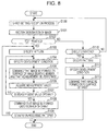
- FIG. 8 is a flowchart illustrating the flow of the operation of the image forming apparatus
- FIG. 9 illustrates an example of an operable screen displayed on a display section of the image forming apparatus
- FIG. 10 illustrates an example of a selection range table
- FIG. 11 illustrates a functional configuration of a controller according to a modification
- FIG. 12 is a flowchart illustrating the flow of a sheet-setting reception process.
- FIG. 1 illustrates the overall configuration of an image forming apparatus 1 according to this exemplary embodiment.
- FIG. 2 is a block diagram illustrating the configuration of the image forming apparatus 1 .
- the image forming apparatus 1 forms an image by using a vertical cavity surface emitting laser (VCSEL).
- VCSEL vertical cavity surface emitting laser
- the image forming apparatus 1 has a controller 11 , a storage section 12 , an operable section 17 , a display section 18 , and an image forming section 10 .
- the image forming section 10 has a developing section 13 , a transfer section 14 , a fixing section 15 , and a transport section 16 .
- the controller 11 has a central processing unit (CPU), a read-only memory (ROM), and a random access memory (RAM).
- the CPU serves as a control device that reads and executes a computer program (which will simply be referred to as “program” hereinafter) stored in the ROM or the storage section 12 so as to control each section of the image forming apparatus 1 .
- the operable section 17 includes operators, such as operable buttons and a touchscreen, for inputting various kinds of commands.
- the operable section 17 receives user operation and supplies a signal according to the operation contents to the controller 11 .
- the display section 18 has a liquid crystal display and displays, for example, various kinds of information commanded by the controller 11 .
- the touchscreen of the operable section 17 may be disposed over the liquid crystal display of the display section 18 .
- the touchscreen is formed of a transparent material so as to allow the user to view an image displayed on the liquid crystal display of the display section 18 .
- the transport section 16 has a container and a transport roller.
- the container accommodates therein sheets P as media cut to a predetermined size.
- the sheets P accommodated in the container are fetched one-by-one by the transport roller in accordance with a command from the controller 11 and are transported to the transfer section 14 via a sheet transport path.
- the media are not limited to paper sheets and may be, for example, resinous sheets. In other words, the media may be of any type onto which images are recordable onto the surfaces thereof.
- the developing section 13 includes an image bearing member 31 , a charging unit 32 , an exposure device 33 , a developing unit 34 , a measuring unit 35 , and a drum cleaner 36 .
- the image bearing member 31 has a charge generation layer and a charge transport layer and is rotated in a direction of an arrow D 13 by a driver (not shown).
- the charging unit 32 electrostatically charges the surface of the image bearing member 31 .
- FIGS. 3A and 3B schematically illustrate the exposure device 33 .
- the exposure device 33 has a light source 330 , a polygonal mirror 331 , a lens unit 332 , and a reflecting mirror 333 .
- FIGS. 4A and 4B schematically illustrate the light source 330 .
- the light source 330 shown in FIG. 4A is a vertical cavity surface emitting laser in which 32 light emitting members (e 11 to e 48 ) are two-dimensionally arranged over a surface of a substrate. Each light emitting member radiates light in a direction orthogonal to the substrate.
- the light emitting members are arranged in a matrix of eight rows in a first scanning direction by four columns in a second scanning direction.
- the light source 330 is an example of a light source having multiple light emitting members that emit light from different positions in the second scanning direction. In this case, four columns of light emitting members exist in a scan width, which is the traveling distance in the second scanning direction in a single scan.
- the light source 330 does not have to be a vertical cavity surface emitting laser so long as it is a light source having multiple light emitting members.
- the number and the arrangement of light emitting members included in the light source 330 are not limited to those in the example shown in FIG. 4A .
- the light source 330 radiates laser light based on a predetermined light emission pattern in accordance with an input image.
- a light emission pattern determines whether or not each of the multiple light emitting members included in the light source 330 is to emit light.
- the polygonal mirror 331 shown in FIGS. 3A and 3B has mirrors on side surfaces of the polygonal prism.
- the mirrors reflect the laser light radiated from the light source 330 .
- the polygonal mirror 331 is rotated by a motor (not shown) so as to scan the reflected laser light.
- the lens unit 332 is a lens group having so-called FO lenses and adjusts the scan speed of the laser light reflected by the polygonal mirror 331 and corrects an angle error of the laser light.
- the reflecting mirror 333 reflects the laser light, which has passed through the lens unit 332 , one or more times to change the traveling direction of the laser light, and guides the laser light to the image bearing member 31 electrostatically charged by the charging unit 32 . Accordingly, the exposure device 33 radiates the laser light onto the electrostatically-charged surface of the image bearing member 31 so that a latent image is retained on the image bearing member 31 .
- the image described above may be read by the controller 11 from the storage section 12 in accordance with a command received as a result of the user operating the operable section 17 , or may be acquired by the controller 11 from an external device via a communication unit (not shown).
- the external device is, for example, a reading device that reads an original image or a storage device that stores therein data indicating an image.
- the developing unit 34 accommodates therein a two-component developer that contains a monochrome toner, such as a black toner, and a magnetic carrier, such as ferrite powder.
- a monochrome toner such as a black toner
- a magnetic carrier such as ferrite powder.
- the tips of a magnetic brush formed in the developing unit 34 come into contact with the surface of the image bearing member 31 so that the toner adheres to an area of the surface of the image bearing member 31 exposed to the laser light from the exposure device 33 , whereby an image is formed (developed) on the image bearing member 31 . Since the developing unit 34 shown in FIG. 1 supplies a monochrome toner, a monochrome image is formed on the image bearing member 31 .
- the measuring unit 35 measures the density of the image formed on the image bearing member 31 by using a light emitting element, such as a light emitting diode (LED), to radiate light onto the surface of the image bearing member 31 and by capturing the light reflected therefrom by using a light receiving element, such as a photodiode.
- a light emitting element such as a light emitting diode (LED)
- LED light emitting diode
- the drum cleaner 36 is, for example, a cleaning blade that removes non-transferred toner remaining on the surface of the image bearing member 31 after an image transfer process. Specifically, the drum cleaner 36 removes unwanted toner from the image bearing member 31 so as to prepare for a subsequent image forming process.
- the transfer section 14 shown in FIG. 1 is a transfer device of a direct transfer type and has a belt 41 , a transfer roller 42 , and a belt transport roller 43 .
- the transfer section 14 transfers the image formed by the developing section 13 onto a sheet P of a predetermined paper type set in accordance with user operation.
- the belt 41 is an endless belt member that is extended between the transfer roller 42 and the belt transport roller 43 .
- the transfer roller 42 transfers the image on the surface of the image bearing member 31 onto the sheet P transported from the transport section 16 .
- At least one of the transfer roller 42 and the belt transport roller 43 is rotated by a driver (not shown), thus causing the belt 41 to rotate.
- the sheet P having the image transferred thereon from the image bearing member 31 by the transfer roller 42 is transported in a direction of an arrow D 14 by the rotating belt 41 .
- the fixing section 15 has a heating roller 51 and a pressing roller 52 .
- the pressing roller 52 presses the sheet P transported by the belt 41 of the transfer section 14 onto the heating roller 51 .
- the heating roller 51 heats the sheet P pressed by the pressing roller 52 so as to fix the image transferred on the sheet P.
- the sheet P having the image fixed thereon is ejected from an upper ejection port of the image forming apparatus 1 and is placed on a sheet tray.
- the image is output to the sheet P in accordance with the functions of these components of the image forming section 10 .
- the storage section 12 is a mass storage unit, such as a hard disk drive, and stores a program to be read by the CPU of the controller 11 . Moreover, as shown in FIG. 2 , the storage section 12 stores a development-condition database (DB) 120 and a pattern table 121 .
- DB development-condition database
- FIG. 5 illustrates an example of the development-condition DB 120 .
- the development-condition DB 120 is a database that has a list 1201 and a development-condition table 1202 .
- the list 1201 has pattern IDs serving as identification information for candidate light emission patterns.
- the development-condition table 1202 has, for each pattern ID written in the list 1201 , a combination of a development condition item and a development condition value to be applied to the light emission pattern identified based on that pattern ID.
- the development condition items include, for example, a development bias, an exposure light intensity, and a toner concentration.
- a development bias is a voltage that the charging unit 32 applies between the image bearing member 31 and the developing unit 34 .
- An exposure light intensity is the intensity of a light beam to be radiated from the light source 330 .
- a toner concentration is the concentration of toner in the developer accommodated in the developing unit 34 . In an initial state, the values in the development-condition table 1202 are not set.
- FIG. 6 illustrates an example of the pattern table 121 .
- the pattern table 121 has light-emitting-member IDs, which are pieces of identification information for light emitting members that are to actually emit light based on that light emission pattern. If a circle is given to the field of a light-emitting-member ID associated with a pattern ID, the light emitting member of that light-emitting-member ID emits light based on the light emission pattern of that pattern ID. If an “X” is given, light is not to be emitted from the light emitting member.
- FIG. 7 illustrates a functional configuration of the controller 11 that controls the image forming apparatus 1 .
- the controller 11 executes the aforementioned program so as to function as a first reception section 111 , an adjustment command section 112 , an acquisition section 113 , a condition specifying section 114 , and an image-formation command section 115 .
- the first reception section 111 receives the contents of the operation. If the operation received by the first reception section 111 designates test printing, which will be described later, or does not designate a light emission pattern, the first reception section 111 specifies a light emission pattern by sequentially reading a pattern ID from the list 1201 in the development-condition DB 120 , reads the contents of the development-condition table 1202 associated with that light emission pattern, and specifies a development condition to be applied to that light emission pattern.
- the adjustment command section 112 refers to the pattern table 121 and commands the image forming section 10 to perform a developing process based on the light emission pattern and the development condition specified by the first reception section 111 .
- the image forming section 10 receiving this command causes the developing section 13 to form an adjustment image for the development condition onto the surface of the image bearing member 31 .
- the measuring unit 35 measures the density of the adjustment image.
- the adjustment command section 112 commands the image forming section 10 to form a latent image based on an input image onto the image bearing member 31 by using the light source 330 having the multiple light emitting members.
- the acquisition section 113 acquires a measurement value from the measuring unit 35 , which has measured the density of the adjustment image formed on the image bearing member 31 in accordance with the command from the adjustment command section 112 .
- the condition specifying section 114 compares the acquired measurement value with a predetermined target value and changes the development condition so that the measurement value becomes closer to the target value.
- the adjustment command section 112 commands the developing section 13 to perform a developing process under the changed development condition, and the acquisition section 113 acquires a measurement value.
- the condition specifying section 114 causes the development-condition DB 120 to store the development condition corresponding to when the measurement value becomes close to a threshold value for the target value as a result of repeating the above process as a development condition corresponding to that light emission pattern.
- the condition specifying section 114 specifies one development condition corresponding to one light emission pattern of the light source 330 based on the measurement value acquired by the acquisition section 113 .
- the development condition items include, for example, a development bias, an exposure light intensity, and a toner concentration.
- the condition specifying section 114 specifies at least one development condition from among the intensity of light to be emitted from the multiple light emitting members included in the light source 330 , the concentration of the developer to be supplied by the developing section 13 , and the voltage to be applied to the image bearing member 31 .
- the image-formation command section 115 refers to the development-condition DB 120 and the pattern table 121 , sets a development condition in the development-condition table 1202 for each light emission pattern listed in the list 1201 in the development-condition DB 120 , and commands the image forming section 10 to form and develop a latent image onto the image bearing member 31 based on an image input to the controller 11 .
- the image-formation command section 115 commands the transport section 16 to transport a sheet P, commands the transfer section 14 to transfer the image from the image bearing member 31 onto the sheet P, and commands the fixing section 15 to fix the image transferred on the sheet P. Consequently, the image formed on the image bearing member 31 based on the development condition specified for each light emission pattern is output to the sheet P.
- the image-formation command section 115 commands the image forming section 10 to form multiple images onto the image bearing member 31 by using multiple light emission patterns and to output the images to sheets P in accordance with development conditions specified by the condition specifying section 114 .
- the first reception section 111 receives a designation of a light emission pattern from the user. If the operation contents received by the first reception section 111 include a designation of a light emission pattern, the image-formation command section 115 commands the image forming section 10 to form an image onto the image bearing member 31 based on the designated light emission pattern and transfer and output that image onto a sheet P.
- FIG. 8 is a flowchart illustrating the flow of the operation of the image forming apparatus 1 .
- FIG. 9 illustrates an example of an operable screen displayed on the display section 18 of the image forming apparatus 1 .
- the controller 11 causes the display section 18 to display the operable screen shown in FIG. 9 and to receive user operation.
- a region R 1 is used for designating a light emission pattern.
- a button B 11 included in the region R 1 is for controlling the light source 330 to cause 16 of 32 light emitting members to radiate “16” beams.
- the operable screen displays five candidate light emission patterns corresponding to buttons B 11 to B 15 .
- a button B 16 is to be used by the user for setting a light emission pattern by editing the light emission statuses of the individual light emitting members.
- a region R 2 is used for commanding that test printing be performed for forming an input image onto a sheet P based on each of the aforementioned five candidate light emission patterns.
- the region R 2 has a button B 21 for commanding that test printing be performed and a button B 22 for stopping the test printing.
- test printing in which a light emission pattern is not designated is executed.
- the button B 22 the test printing is stopped.
- a region R 3 is for prompting the user to output an image as well as for presenting information.
- the region R 3 has a button B 31 for receiving an input of an image and displaying a file name, which is identification information, of the input image, and also has a message field B 32 that displays a character string for prompting the user to press any of the buttons included in the region R 1 to select the number of beams to be output.
- step S 101 the controller 11 determines whether or not the user operation indicates test printing. If it is determined that the user operation indicates test printing (YES in step S 102 ), the controller 11 refers to the list 1201 in the development-condition DB 120 , sequentially reads each of the listed pattern IDs, and specifies a light emission pattern in step S 103 .
- the controller 11 that has specified the light emission pattern specifies a development condition associated with that light emission pattern from the development-condition table 1202 in the development-condition DB 120 in step S 104 .
- the controller 11 then commands the developing section 13 to form an adjustment image onto the surface of the image bearing member 31 and to measure the density of the image formed on the surface.
- step S 106 When the controller 11 acquires a measurement value from the measuring unit 35 of the developing section 13 in step S 106 , the controller 11 compares the measurement value with a predetermined target value and determines whether or not the measurement value is an optimal value in step S 107 . If it is determined that the acquired measurement value is not an optimal value (NO in step S 107 ), the controller 11 returns the process to step S 104 . In step S 104 , the controller 11 changes the contents written in the development-condition table 1202 in the development-condition DB 120 so as to specify a new development condition.
- the controller 11 stores the current development condition into the development-condition DB 120 in association with the current light emission pattern and commands the transfer section 14 , the transport section 16 , and the fixing section 15 in addition to the developing section 13 to form the input image onto the sheet P by using the light source 330 emitting light based on the development condition and the light emission pattern in step S 108 .
- step S 109 the controller 11 determines whether or not there is an unprocessed pattern ID written in the list 1201 in the development-condition DB 120 . If it is determined that there is an unprocessed pattern ID (YES in step S 109 ), the controller 11 returns the process to step S 103 . In step S 103 , a light emission pattern identified based on the unprocessed pattern ID is specified.
- step S 109 the controller 11 ends the process.
- step S 102 the controller 11 determines whether or not the relevant operation designates a light emission pattern and indicates a command for executing printing in step S 110 . If it is determined that the user operation does not designate a light emission pattern and does not indicate a command for executing printing (NO in step S 110 ), the controller 11 returns the process to the step prior to step S 101 .
- the controller 11 specifies the designated light emission pattern in step S 111 and specifies a development condition associated with that light emission pattern in the development-condition DB 120 in step S 112 . Then, the controller 11 commands that the input image be formed on the sheet P by using the light source 330 emitting light based on the specified development condition and the specified light emission pattern in step S 113 and ends the process.
- the user obtains sheets P having images formed thereon based on optimal development conditions respectively for multiple candidate light emission patterns.
- the user may visually compare the images formed on the sheets P and select a less-disordered light emission pattern.
- the controller 11 of the image forming apparatus 1 may command the image forming section 10 to form multiple latent images based on an image input by the user onto the image bearing member 31 in accordance with different light emission patterns, develop the latent images, and output the multiple developed images onto the sheets P.
- the controller 11 may receive a designation of a light emission pattern selected by the user from among the aforementioned candidate light emission patterns. Accordingly, when forming an image using a light source having multiple light emitting members, a light emission pattern suitable for the characteristics of the image is specified.
- the image forming apparatus 1 forms an image onto a sheet P based on a light emission pattern whose pattern ID is written in the list 1201 in the development-condition DB 120 .
- the image forming apparatus 1 may receive a designation of an image forming condition.
- the storage section 12 of the image forming apparatus 1 may store a selection range table 122 indicated by a dashed line in FIG. 2 .
- FIG. 10 illustrates an example of the selection range table 122 .
- the selection range table 122 indicates the range of candidate light emission patterns for each image forming condition.
- a sheet ID indicating the type of sheet P is indicated as an image forming condition in the selection range table 122 .
- the type of sheet P indicated by a sheet ID is, for example, the size or the basis weight thereof.
- multiple pattern IDs corresponding to each sheet ID are each given a circle or an “X” indicating whether or not the light emission pattern identified based on that pattern ID is a candidate. If a pattern ID is given a circle, the light emission pattern identified based on that pattern ID is a candidate. If a pattern ID is given an “X”, the light emission pattern identified based on that pattern ID is not a candidate.
- FIG. 11 illustrates a functional configuration of a controller 11 according to this modification.
- the controller 11 executes a program read from the storage section 12 so as to function as a second reception section 116 , a range specifying section 117 , and a presentation command section 118 .
- the second reception section 116 receives a designation of a condition for forming an image onto a sheet P.
- a sheet ID indicating the type of sheet P is designated as the condition.
- the range specifying section 117 refers to the selection range table 122 and specifies candidates for multiple light emission patterns associated with the designated sheet ID. Specifically, the range specifying section 117 specifies the range of patterns based on which the light emitting members of the light source 330 emit light in accordance with the condition indicated by the designation received by the second reception section 116 .
- the range specifying section 117 writes the specified range into the list 1201 in the development-condition DB 120 .
- the presentation command section 118 commands the display section 18 to display the pattern IDs of these light emission patterns.
- the presentation command section 118 commands the display section 18 (presenting device) to display (present) the range specified by the range specifying section 117 .
- the display section 18 is merely an example of a component that presents the aforementioned range in accordance the command from the presentation command section 118 , and this component that presents the range is not limited to the display section 18 .
- the image forming apparatus 1 may have a reproducing unit that presents this range to the user by reproducing audio obtained by reading out aloud each of the names of the candidate light emission patterns included in this range.
- step S 100 when the user commands that a sheet P be set by operating the operable section 17 , the controller 11 of the image forming apparatus 1 performs a sheet-setting reception process (step S 100 ), as indicated by a dashed line in FIG. 8 .
- FIG. 12 is a flowchart illustrating the flow of the sheet-setting reception process.
- the controller 11 receives a sheet designation indicated by the operation in step S 201 , specifies a sheet ID, which is identification information of the sheet P, and refers to the selection range table 122 so as to specify a light emission pattern range corresponding to the sheet ID in step S 202 .
- the controller 11 commands the display section 18 to present the range in step S 203 and ends the process.
- the specified light emission pattern range is displayed by being allocated to the buttons B 11 to B 15 in the operable screen shown in FIG. 9 .
- the user viewing this operable screen confirms that the light emission pattern range is set in accordance with the sheet ID designated by the user.
- the type of sheet P indicated by the sheet ID is, for example, the size or the basis weight thereof and often affects the time it takes for toner transfer and toner fixation. Therefore, in the image forming apparatus 1 , each sheet ID is associated with the transport speed of the sheet P in advance. If the transport speed exceeds a threshold value, some of the light emitting members of the light source 330 are caused not to emit light, sometimes making it difficult to perform a developing process. Therefore, with regard to a sheet P for which the transport speed is set to be higher than the threshold value, the number of light emitting members that are to emit light in association with the relevant sheet ID is set to be larger than that for a sheet P for which the transport speed is lower than the above set transport speed. Accordingly, the image forming apparatus 1 makes the user select a light emission pattern range suitable for the image forming condition even when the number of candidate light emission patterns is limited.
- the second reception section 116 may receive a condition other than a designation of a sheet ID.
- the second reception section 116 may receive a designation for collectively forming two images onto a single sheet P or a designation for prioritizing toner amount over image quality.
- the second reception section 116 may receive a designation of the transport speed of a sheet P. Specifically, the second reception section 116 may receive a designation of a condition related to the speed at which a medium is transported.
- the second reception section 116 may receive a designation of a condition related to a screen of an input image as the above-described image forming condition.
- a screen expresses an intermediate color by using halftone dots.
- An input image may sometimes be prescreened before the image is input. There are some screens that are known in advance to interfere with any of the light emission patterns due to, for example, the number of lines thereof.
- the selection range table 122 has written therein candidates for light emission patterns for each screen, and the controller 11 refers to the selection range table 122 to narrow down the candidates for light emission patterns so that interference fringes known to occur in advance may be avoided.
- the image forming apparatus 1 may add the pattern ID of the light emission pattern for the light emitting members used for forming this image to this image and form the image onto the sheet P.
- the image-formation command section 115 may command the image forming section 10 to add the pattern ID for identifying the light emission pattern for the light emitting members to each of multiple images, form the image onto the image bearing member 31 , and output the image to the sheet P.
- the developing section 13 is configured to form a monochrome image onto the image bearing member 31 by using the developing unit 34 that supplies a monochrome toner.
- the developing section 13 may be configured to use multiple developing units to form a color image onto a sheet P by using toners of multiple colors.
- the developing section 13 may be of a tandem type in which multiple image bearing members 31 are arranged in the moving direction of a transfer belt.
- a development condition may be set for each of these colors.
- the transfer section 14 transfers an image onto a sheet P, which is a medium, directly from the image bearing member 31 of the developing section 13 based on a direct transfer method.
- the transfer section 14 may be configured to perform the transfer process based on an indirect transfer method.
- the transfer section 14 may have an intermediate transfer member, such as an intermediate transfer belt, which transfers an image formed on the image bearing member 31 , and may transfer the transferred image onto a medium, such as a sheet P, from this intermediate transfer member.
- the program to be executed by the controller 11 of the image forming apparatus 1 may be provided in a stored state in a computer readable storage medium, which may be, for example, a magnetic storage medium, such as a magnetic tape or a magnetic disk; an optical storage medium, such as an optical disk; a magneto-optical storage medium; or a semiconductor memory. Furthermore, this program may be downloaded via a communication line, such as the Internet.
- a controller described above as the controller 11 various types of devices other than the CPU may be used. For example, a dedicated processor may be used.
- the controller 11 of the image forming apparatus 1 forms an adjustment image onto the image bearing member 31 , measures the density thereof, changes the development condition until the measurement value becomes an optimal value, and specifies an optimal development condition corresponding to each light emission pattern.
- this development-condition specifying process does not have to be performed every time test printing is to be performed.
- the controller 11 may directly specify a development condition stored in the development-condition DB 120 , and the controller 11 may proceed to step S 108 after step S 104 in FIG. 8 .
- the controller 11 does not have to function as the adjustment command section 112 , the acquisition section 113 , and the condition specifying section 114 .
Landscapes
- Physics & Mathematics (AREA)
- Engineering & Computer Science (AREA)
- General Physics & Mathematics (AREA)
- General Engineering & Computer Science (AREA)
- Theoretical Computer Science (AREA)
- Optics & Photonics (AREA)
- Control Or Security For Electrophotography (AREA)
Abstract
Description
Claims (11)
Applications Claiming Priority (2)
| Application Number | Priority Date | Filing Date | Title |
|---|---|---|---|
| JP2015247305A JP6601205B2 (en) | 2015-12-18 | 2015-12-18 | Control device, image forming apparatus, and program |
| JP2015-247305 | 2015-12-18 |
Publications (2)
| Publication Number | Publication Date |
|---|---|
| US20170177981A1 US20170177981A1 (en) | 2017-06-22 |
| US9836674B2 true US9836674B2 (en) | 2017-12-05 |
Family
ID=59066458
Family Applications (1)
| Application Number | Title | Priority Date | Filing Date |
|---|---|---|---|
| US15/148,263 Active US9836674B2 (en) | 2015-12-18 | 2016-05-06 | Control device forming a plurality of latent images based on one input image by using a light source including a plurality of light emitting members, and control method, image forming apparatus, and non-transitory computer readable medium thereof |
Country Status (2)
| Country | Link |
|---|---|
| US (1) | US9836674B2 (en) |
| JP (1) | JP6601205B2 (en) |
Families Citing this family (1)
| Publication number | Priority date | Publication date | Assignee | Title |
|---|---|---|---|---|
| CN111556621A (en) * | 2020-04-23 | 2020-08-18 | 北京智米科技有限公司 | Lamp and control method and device thereof |
Citations (5)
| Publication number | Priority date | Publication date | Assignee | Title |
|---|---|---|---|---|
| US20090080948A1 (en) * | 2007-09-21 | 2009-03-26 | Canon Kabushiki Kaisha | Image forming apparatus |
| US20090129804A1 (en) * | 2007-11-20 | 2009-05-21 | Canon Kabushiki Kaisha | Image generating apparatus and calibration method therefor |
| JP2010139987A (en) | 2008-12-15 | 2010-06-24 | Konica Minolta Business Technologies Inc | Image forming apparatus |
| US20100300310A1 (en) * | 2009-05-28 | 2010-12-02 | Sony Corporation | Print apparatus, print method, and print program |
| EP2444850A2 (en) * | 2010-09-15 | 2012-04-25 | Ricoh Company, Ltd. | Image forming apparatus and program |
Family Cites Families (7)
| Publication number | Priority date | Publication date | Assignee | Title |
|---|---|---|---|---|
| US5245443A (en) * | 1990-10-02 | 1993-09-14 | Southwest Software, Inc. | Method and apparatus for calibrating image output from an image generating device |
| JP2007129558A (en) * | 2005-11-04 | 2007-05-24 | Canon Inc | Image forming apparatus and image processing apparatus |
| JP5524576B2 (en) * | 2009-11-10 | 2014-06-18 | キヤノン株式会社 | Image forming apparatus and calibration method |
| JP5521576B2 (en) * | 2010-01-27 | 2014-06-18 | 富士ゼロックス株式会社 | Exposure apparatus and image forming apparatus |
| JP6029315B2 (en) * | 2012-04-26 | 2016-11-24 | キヤノン株式会社 | Image forming apparatus |
| JP2014137498A (en) * | 2013-01-17 | 2014-07-28 | Konica Minolta Inc | Image forming apparatus |
| JP6261323B2 (en) * | 2013-12-18 | 2018-01-17 | キヤノン株式会社 | Image forming apparatus and control method |
-
2015
- 2015-12-18 JP JP2015247305A patent/JP6601205B2/en active Active
-
2016
- 2016-05-06 US US15/148,263 patent/US9836674B2/en active Active
Patent Citations (5)
| Publication number | Priority date | Publication date | Assignee | Title |
|---|---|---|---|---|
| US20090080948A1 (en) * | 2007-09-21 | 2009-03-26 | Canon Kabushiki Kaisha | Image forming apparatus |
| US20090129804A1 (en) * | 2007-11-20 | 2009-05-21 | Canon Kabushiki Kaisha | Image generating apparatus and calibration method therefor |
| JP2010139987A (en) | 2008-12-15 | 2010-06-24 | Konica Minolta Business Technologies Inc | Image forming apparatus |
| US20100300310A1 (en) * | 2009-05-28 | 2010-12-02 | Sony Corporation | Print apparatus, print method, and print program |
| EP2444850A2 (en) * | 2010-09-15 | 2012-04-25 | Ricoh Company, Ltd. | Image forming apparatus and program |
Also Published As
| Publication number | Publication date |
|---|---|
| JP2017111378A (en) | 2017-06-22 |
| US20170177981A1 (en) | 2017-06-22 |
| JP6601205B2 (en) | 2019-11-06 |
Similar Documents
| Publication | Publication Date | Title |
|---|---|---|
| US10306103B2 (en) | Printing apparatus, control method for printing apparatus, and storage medium | |
| US7486414B2 (en) | Image forming device, pattern formation method and storage medium storing its program | |
| US8995848B2 (en) | Image forming apparatus for measuring a density of a test image and performing output paper density adjustment based on a result of the measurement | |
| US20050217162A1 (en) | Accessory devices for firearms | |
| US8885213B2 (en) | Imaging forming apparatus | |
| US9202147B2 (en) | Image forming system including an image reading unit in a paper conveying path downstream from an image forming unit | |
| CN101339388B (en) | Image processing apparatus and control method thereof | |
| US9509876B2 (en) | Printing apparatus, control method for printing apparatus, and storage medium | |
| US10353315B2 (en) | Image forming apparatus that sequentially executes adjustment operations corresponding to a plurality of adjustment items | |
| US8259146B2 (en) | Image forming apparatus, control method therefor, and program | |
| US9658564B1 (en) | Control device, control method, image forming apparatus, and non-transitory computer readable medium | |
| CN105549352B (en) | Image forming apparatus and printing inspection system | |
| US9836674B2 (en) | Control device forming a plurality of latent images based on one input image by using a light source including a plurality of light emitting members, and control method, image forming apparatus, and non-transitory computer readable medium thereof | |
| US9860405B2 (en) | Printing apparatus, printing apparatus control method, and a storage medium | |
| JP5060174B2 (en) | Image forming apparatus | |
| US8666265B2 (en) | Image forming apparatus and image forming method of electrophotography | |
| US9846369B2 (en) | Image forming apparatus capable of adjusting laser beams emitted from a plurality of light sources, and method of controlling image forming apparatus | |
| US9158224B2 (en) | Image forming apparatus generating horizontal synchronization signals and method of image forming | |
| US11847359B2 (en) | Image forming system for inspecting an image formed on a sheet based on an image editing process intensity | |
| CN108732879A (en) | Image forming apparatus | |
| US10162297B2 (en) | Image forming apparatus and method for controlling the same and computer-readable recording medium | |
| JP2007030302A (en) | Image forming apparatus, apparatus for forming color conversion parameter, test image forming method and program | |
| JP7722071B2 (en) | Image forming apparatus, light emission control method and program | |
| JP2018078426A (en) | Image forming apparatus and method | |
| JP5476727B2 (en) | Image evaluation method, image evaluation apparatus, and image forming apparatus |
Legal Events
| Date | Code | Title | Description |
|---|---|---|---|
| AS | Assignment |
Owner name: FUJI XEROX CO., LTD., JAPAN Free format text: ASSIGNMENT OF ASSIGNORS INTEREST;ASSIGNOR:NAGATA, KENJO;REEL/FRAME:038486/0117 Effective date: 20160323 |
|
| STCF | Information on status: patent grant |
Free format text: PATENTED CASE |
|
| MAFP | Maintenance fee payment |
Free format text: PAYMENT OF MAINTENANCE FEE, 4TH YEAR, LARGE ENTITY (ORIGINAL EVENT CODE: M1551); ENTITY STATUS OF PATENT OWNER: LARGE ENTITY Year of fee payment: 4 |
|
| AS | Assignment |
Owner name: FUJIFILM BUSINESS INNOVATION CORP., JAPAN Free format text: CHANGE OF NAME;ASSIGNOR:FUJI XEROX CO., LTD.;REEL/FRAME:058287/0056 Effective date: 20210401 |
|
| MAFP | Maintenance fee payment |
Free format text: PAYMENT OF MAINTENANCE FEE, 8TH YEAR, LARGE ENTITY (ORIGINAL EVENT CODE: M1552); ENTITY STATUS OF PATENT OWNER: LARGE ENTITY Year of fee payment: 8 |